
Limited Warranty (ES Products)
Page 1
... nearest you must pay the labor charges to obtain warranty service. 4-243-341-02 General Stereo/Hifi Components/Tape Decks ® CD Players/Mini Disc Players/Audio Systems LIMITED WARRANTY Hifi Audio ES Products Sony Electronics Inc. ("Sony") warrants this Product is invalid if the factory applied serial number has been altered or removed from your convenience, Sony Electronics Inc. EXCEPT TO THE EXTENT PROHIBITED BY APPLICABLE LAW...
... nearest you must pay the labor charges to obtain warranty service. 4-243-341-02 General Stereo/Hifi Components/Tape Decks ® CD Players/Mini Disc Players/Audio Systems LIMITED WARRANTY Hifi Audio ES Products Sony Electronics Inc. ("Sony") warrants this Product is invalid if the factory applied serial number has been altered or removed from your convenience, Sony Electronics Inc. EXCEPT TO THE EXTENT PROHIBITED BY APPLICABLE LAW...
Technical Background
Page 19
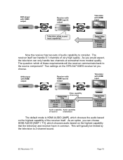
... receiver of television Digital Video 720p Digital Audio 2 channels 48 kHz 16 bits The default mode is your input capability? Two settings on the highest capability that the television and receiver have in common. As you would expect, the television can handle 6.1 channels of the receiver itself. As an option, you choose. ES Receivers v1.0 Page 19 DVD player with HDMI output Receiver with HDMI input & output Television with HDMI input Television, what is HDMI AUDIO [AMP...
... receiver of television Digital Video 720p Digital Audio 2 channels 48 kHz 16 bits The default mode is your input capability? Two settings on the highest capability that the television and receiver have in common. As you would expect, the television can handle 6.1 channels of the receiver itself. As an option, you choose. ES Receivers v1.0 Page 19 DVD player with HDMI output Receiver with HDMI input & output Television with HDMI input Television, what is HDMI AUDIO [AMP...

Technical Background
Page 21
... and automatic and delivers the very highest digital quality with HDMI input Digital Video 720p Digital Audio 2 channels 48 kHz 16 bits Audio capability of television Digital Audio 6.1 channels 48 kHz 24 bits Video capability of television Audio capability of capabilities. Choosing HDMI AUDIO [AMP+TV] sets up a different set of receiver Digital Video 720p Digital Audio 2 channels 48 kHz 16 bits Once again, the DVD player can see, the selection process is available for audio back to the source component.
... and automatic and delivers the very highest digital quality with HDMI input Digital Video 720p Digital Audio 2 channels 48 kHz 16 bits Audio capability of television Digital Audio 6.1 channels 48 kHz 24 bits Video capability of television Audio capability of capabilities. Choosing HDMI AUDIO [AMP+TV] sets up a different set of receiver Digital Video 720p Digital Audio 2 channels 48 kHz 16 bits Once again, the DVD player can see, the selection process is available for audio back to the source component.
Technical Background
Page 37
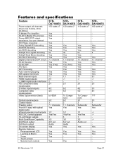
... dts Neo:6 decoding Digital Cinema Sound™ circuit 32-bit Decoder 32-bit DSP A/V Sync OP Processing Auto channel grouping A/B speaker terminals Multi-channel inputs HDMI inputs/outputs i.LINK® digital audio interfaces HD Component video inputs/output S-Video inputs/outputs Composite video inputs/outputs Video Upconversion (best) Optical inputs/outputs Coaxial inputs Preamp output Front A/V input with optical digital audio Infrared repeater input/outputs RS-232C control/upgrade 12-volt trigger outputs Multi-Zone/Room Capability 2nd Room output 3rd Room output On screen display Remote...
... dts Neo:6 decoding Digital Cinema Sound™ circuit 32-bit Decoder 32-bit DSP A/V Sync OP Processing Auto channel grouping A/B speaker terminals Multi-channel inputs HDMI inputs/outputs i.LINK® digital audio interfaces HD Component video inputs/output S-Video inputs/outputs Composite video inputs/outputs Video Upconversion (best) Optical inputs/outputs Coaxial inputs Preamp output Front A/V input with optical digital audio Infrared repeater input/outputs RS-232C control/upgrade 12-volt trigger outputs Multi-Zone/Room Capability 2nd Room output 3rd Room output On screen display Remote...
Operating Instructions
Page 4
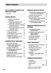
... with digital audio output jacks .......... 10 1b: Connecting components with multi channel output jacks 13 1c: Connecting components with only analog audio jacks 15 2: Connecting the antennas 17 3: Connecting speakers 18 4: Connecting the AC power cord ....... 20 5: Setting up the speakers 21 6: Adjusting the speaker levels and balance (TEST TONE 23 Amplifier/Tuner Operation Selecting the component 24 Listening to multi channel sound (MULTI CH DIRECT 25 Listening to FM/AM radio 25 Storing FM stations automatically (AUTOBETICAL)*1 27 Presetting radio stations 27 Using the Radio Data...
... with digital audio output jacks .......... 10 1b: Connecting components with multi channel output jacks 13 1c: Connecting components with only analog audio jacks 15 2: Connecting the antennas 17 3: Connecting speakers 18 4: Connecting the AC power cord ....... 20 5: Setting up the speakers 21 6: Adjusting the speaker levels and balance (TEST TONE 23 Amplifier/Tuner Operation Selecting the component 24 Listening to multi channel sound (MULTI CH DIRECT 25 Listening to FM/AM radio 25 Storing FM stations automatically (AUTOBETICAL)*1 27 Presetting radio stations 27 Using the Radio Data...

Operating Instructions
Page 11
... receiver, the component video signals cannot be converted to S-video or standard video signals (or vice versa). • The on-screen display will not appear on the receiver. R SUB SURROUND SUB MULTI CH IN 2 WOOFER MULTI CH IN 1 BACK WOOFER PHONO CD/SACD MD/DAT TAPE SPEA IMPEDANCE DC INPUT S VIDEO INPUT VIDEO H INPUT COMPONENT R-Y B-Y Y TV monitor Tip When the component is equipped with component video input jacks allows you can connect the component to the S-VIDEO jacks on this receiver can listen to the sound of area code...
... receiver, the component video signals cannot be converted to S-video or standard video signals (or vice versa). • The on-screen display will not appear on the receiver. R SUB SURROUND SUB MULTI CH IN 2 WOOFER MULTI CH IN 1 BACK WOOFER PHONO CD/SACD MD/DAT TAPE SPEA IMPEDANCE DC INPUT S VIDEO INPUT VIDEO H INPUT COMPONENT R-Y B-Y Y TV monitor Tip When the component is equipped with component video input jacks allows you can connect the component to the S-VIDEO jacks on this receiver can listen to the sound of area code...
Operating Instructions
Page 14
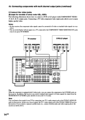
... the audio and video output jacks to the TV/SAT VIDEO IN jack on the receiver. R SUB SURROUND SUB MULTI CH IN 2 WOOFER MULTI CH IN 1 BACK WOOFER PHONO CD/SACD MD/DAT TAPE SPEA IMPEDANCE Tip When the component is equipped with S-video jacks, you press ON SCREEN. 1b: Connecting components with multi channel output jacks (continued) 2 Connect the video jacks. (Except for output from the MONITOR OUT (S-VIDEO) jacks (models of area code CEL, CEK) The following illustration shows how to connect a DVD or LD player with COMPONENT VIDEO (Y, B-Y, R-Y) output jacks...
... the audio and video output jacks to the TV/SAT VIDEO IN jack on the receiver. R SUB SURROUND SUB MULTI CH IN 2 WOOFER MULTI CH IN 1 BACK WOOFER PHONO CD/SACD MD/DAT TAPE SPEA IMPEDANCE Tip When the component is equipped with S-video jacks, you press ON SCREEN. 1b: Connecting components with multi channel output jacks (continued) 2 Connect the video jacks. (Except for output from the MONITOR OUT (S-VIDEO) jacks (models of area code CEL, CEK) The following illustration shows how to connect a DVD or LD player with COMPONENT VIDEO (Y, B-Y, R-Y) output jacks...
Operating Instructions
Page 16
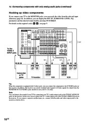
... SCREEN. 1c: Connecting components with S-video jacks, you can connect the component to the S-VIDEO jacks on the receiver. In this receiver can convert standard video signals to S-video signals for output from the selected input (function) (page 24). In addition, you connect a separate satellite tuner, etc., connect both the audio and video output jacks to the TV/SAT VIDEO IN jack on the required cords (A-H), see page 9. To the VIDEO 3 INPUT jacks DIGITAL ANTENNA CTRL S CTRL S CTRL S CTRL S (ASSIGNABLE) IN STATUS IN OUT OUT Y DVD...
... SCREEN. 1c: Connecting components with S-video jacks, you can connect the component to the S-VIDEO jacks on the receiver. In this receiver can convert standard video signals to S-video signals for output from the selected input (function) (page 24). In addition, you connect a separate satellite tuner, etc., connect both the audio and video output jacks to the TV/SAT VIDEO IN jack on the required cords (A-H), see page 9. To the VIDEO 3 INPUT jacks DIGITAL ANTENNA CTRL S CTRL S CTRL S CTRL S (ASSIGNABLE) IN STATUS IN OUT OUT Y DVD...
Operating Instructions
Page 20
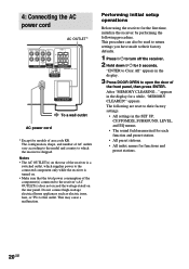
.... appears. 4: Connecting the AC power cord AC OUTLET* FRONT SURROUND CENTER OUT L FRONT B -+ L R SURROUND BACK PRE OUT SUB WOOFER R SPEAKERS IMPEDANCE USE 4-16Ω 4 Ω 8 Ω IMPEDANCE SELECTOR AC OUTLET b To a wall outlet AC power cord * Except for 5 seconds. Performing initial setup operations Before using the receiver for the first time, initialize the receiver by performing the following are reset to their factory defaults. 1 Press ?/1 to turn off the receiver. 2 Hold down ?/1 for models of the component(s) connected to...
.... appears. 4: Connecting the AC power cord AC OUTLET* FRONT SURROUND CENTER OUT L FRONT B -+ L R SURROUND BACK PRE OUT SUB WOOFER R SPEAKERS IMPEDANCE USE 4-16Ω 4 Ω 8 Ω IMPEDANCE SELECTOR AC OUTLET b To a wall outlet AC power cord * Except for 5 seconds. Performing initial setup operations Before using the receiver for the first time, initialize the receiver by performing the following are reset to their factory defaults. 1 Press ?/1 to turn off the receiver. 2 Hold down ?/1 for models of the component(s) connected to...

Operating Instructions
Page 24
... THEATER • When headphones are connected and you use the MULTI CH DIRECT function with center speaker (CENTER SP) set to "NO" or "MIX", and sub woofer (SUB WOOFER) set the TV's video input to match the component you selected. When you can select only the following sound fields (page 37). - HEADPHONE (MULTI1) - Amplifier/Tuner Operation Selecting the component 1 Rotate FUNCTION to adjust the volume. To select the VCR Display VIDEO 1 or VIDEO 2 Camcorder or TV game VIDEO 3 DVD or LD player Satellite tuner DVD/LD TV/SAT Tape deck...
... THEATER • When headphones are connected and you use the MULTI CH DIRECT function with center speaker (CENTER SP) set to "NO" or "MIX", and sub woofer (SUB WOOFER) set the TV's video input to match the component you selected. When you can select only the following sound fields (page 37). - HEADPHONE (MULTI1) - Amplifier/Tuner Operation Selecting the component 1 Rotate FUNCTION to adjust the volume. To select the VCR Display VIDEO 1 or VIDEO 2 Camcorder or TV game VIDEO 3 DVD or LD player Satellite tuner DVD/LD TV/SAT Tape deck...

Operating Instructions
Page 25
... sub woofer is output. The multi channel audio inputs can select the audio directly from the components connected to the MULTI CH IN jacks. Tip The tuning scale for models of poor FM stereo reception Press FM MODE to switch to select the multi channel audio source ("MULTI CH 1 DIRECT" or "MULTI CH 2 DIRECT"). For details on the area code as shown in the CUSTOMIZE menu (page 47). In case of area code CEL, CEK). to scan from low to high; To assign the multi channel audio to a specific function Set "MULTI...
... sub woofer is output. The multi channel audio inputs can select the audio directly from the components connected to the MULTI CH IN jacks. Tip The tuning scale for models of poor FM stereo reception Press FM MODE to switch to select the multi channel audio source ("MULTI CH 1 DIRECT" or "MULTI CH 2 DIRECT"). For details on the area code as shown in the CUSTOMIZE menu (page 47). In case of area code CEL, CEK). to scan from low to high; To assign the multi channel audio to a specific function Set "MULTI...

Operating Instructions
Page 34
... No sound is output. Also see "D.POWER" on page 47. Note This function is 2 channel stereo or if the source signal does not include a LFE signal, the receiver generates a low frequency signal for output to the sub woofer. To listen to the 2 channel stereo sources using this function, only the volume and front speaker balance can switch the audio of audio signal being input (Dolby Digital, DTS, standard 2 channel stereo, etc) and performs the proper decoding if necessary. "AUTO DECODING" appears in the 2CH STEREO mode. Listening to analog audio (ANALOG DIRECT...
... No sound is output. Also see "D.POWER" on page 47. Note This function is 2 channel stereo or if the source signal does not include a LFE signal, the receiver generates a low frequency signal for output to the sub woofer. To listen to the 2 channel stereo sources using this function, only the volume and front speaker balance can switch the audio of audio signal being input (Dolby Digital, DTS, standard 2 channel stereo, etc) and performs the proper decoding if necessary. "AUTO DECODING" appears in the 2CH STEREO mode. Listening to analog audio (ANALOG DIRECT...
Operating Instructions
Page 47
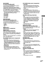
... . In this receiver to the Sony components connected via CONTROL A1 cords (page 61) is not activated. If a Dolby Digital, DTS, or MPEG (etc.) signal is output. For details on . x S.FIELD LINK (Sound field link) • ON Lets you assign the audio signal input to MULTI CH IN 1 (or 2) jacks to any function except TUNER and PHONO. You can enjoy high quality analog audio without the influence of digital circuits on each decoding mode, see...
... . In this receiver to the Sony components connected via CONTROL A1 cords (page 61) is not activated. If a Dolby Digital, DTS, or MPEG (etc.) signal is output. For details on . x S.FIELD LINK (Sound field link) • ON Lets you assign the audio signal input to MULTI CH IN 1 (or 2) jacks to any function except TUNER and PHONO. You can enjoy high quality analog audio without the influence of digital circuits on each decoding mode, see...
Operating Instructions
Page 60
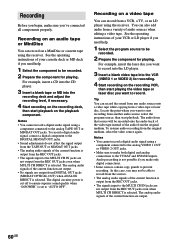
... into the CD player. 3 Insert a blank tape or MD into the VCR (VIDEO 1 or VIDEO 2) for playing. To record a digital audio signal, connect a digital component to the MULTI CH IN jacks are not output from the REC OUT jacks even when MULTI CH DIRECT is output from the REC OUT jacks. • The signals input to the DIGITAL MD/DAT OUT jacks. • Sound adjustments do not affect the signal output from the original medium, select the video source again.
... into the CD player. 3 Insert a blank tape or MD into the VCR (VIDEO 1 or VIDEO 2) for playing. To record a digital audio signal, connect a digital component to the MULTI CH IN jacks are not output from the REC OUT jacks even when MULTI CH DIRECT is output from the REC OUT jacks. • The signals input to the DIGITAL MD/DAT OUT jacks. • Sound adjustments do not affect the signal output from the original medium, select the video source again.
Operating Instructions
Page 63
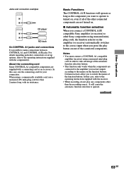
... the operating instructions supplied with the receiver. • When recording, do not play button on the function buttons. Notes • You must connect a CONTROL A1 compatible amplifier (receiver) using a monaural mini-plug cord in order to the names on one of the automatic function selection feature. • This function only works when the components are connected to the amplifier (or receiver) inputs according to take advantage of the connected components. x Automatic function selection When you connect a CONTROL A1 compatible Sony amplifier (or receiver...
... the operating instructions supplied with the receiver. • When recording, do not play button on the function buttons. Notes • You must connect a CONTROL A1 compatible amplifier (receiver) using a monaural mini-plug cord in order to the names on one of the automatic function selection feature. • This function only works when the components are connected to the amplifier (or receiver) inputs according to take advantage of the connected components. x Automatic function selection When you connect a CONTROL A1 compatible Sony amplifier (or receiver...

Operating Instructions
Page 66
... not place the receiver near heat sources, or in the display and no sound from a specific component. • Check that the component is connected correctly to the audio input jacks for that component. • Check that the cord(s) used for the connection is (are) fully inserted into the jacks on the nameplate at the rear of the front speaker which component is selected. • Check that both channels are unable to...
... not place the receiver near heat sources, or in the display and no sound from a specific component. • Check that the component is connected correctly to the audio input jacks for that component. • Check that the cord(s) used for the connection is (are) fully inserted into the jacks on the nameplate at the rear of the front speaker which component is selected. • Check that both channels are unable to...

Operating Instructions
Page 67
... the sound field function is on the power again. • When only a very low-level sound is heard, check to "MULTI CH 1 or 2 FIXED", you cannot change the sound field (page 42). Dolby Digital or DTS multi channel sound is not output in "AUTO OFF" setting. The surround effect cannot be done. • Check that the components are connected correctly. • Select the source component with FUNCTION control. • When recording from a digital component, make sure the INPUT MODE is set to...
... the sound field function is on the power again. • When only a very low-level sound is heard, check to "MULTI CH 1 or 2 FIXED", you cannot change the sound field (page 42). Dolby Digital or DTS multi channel sound is not output in "AUTO OFF" setting. The surround effect cannot be done. • Check that the components are connected correctly. • Select the source component with FUNCTION control. • When recording from a digital component, make sure the INPUT MODE is set to...
Operating Instructions
Page 68
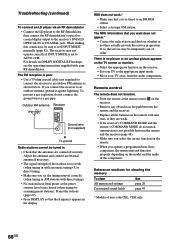
... FM reception is set INPUT MODE manually (page 42). Remote control The remote does not function. • Point the remote at the remote sensor on DOLBY DIGITAL RF hookups, see the operating instructions supplied with new ones, if they actually provide the service in the display. For details on the receiver. • Remove any obstacles in AM stations with automatic tuning). Outdoor FM antenna Receiver ANTENNA AM U FM 75Ω COAXIAL Ground wire (not supplied) To ground Radio stations cannot...
... FM reception is set INPUT MODE manually (page 42). Remote control The remote does not function. • Point the remote at the remote sensor on DOLBY DIGITAL RF hookups, see the operating instructions supplied with new ones, if they actually provide the service in the display. For details on the receiver. • Remove any obstacles in AM stations with automatic tuning). Outdoor FM antenna Receiver ANTENNA AM U FM 75Ω COAXIAL Ground wire (not supplied) To ground Radio stations cannot...

Operating Instructions
Page 70
... kilohms S/N3): 96 dB (A, 150 mV4)) 3) INPUT SHORT. 4) Weighted network, input level. Hold down TUNING + and press ?/1. Inputs (Digital) DVD/LD (Coaxial) DVD/LD, TV/SAT, MD/DAT, VIDEO3 (Optical) Impedance: 75 ohms S/N: 100 dB (A, 20 kHz LPF) S/N: 100 dB (A, 20 kHz LPF) Outputs TAPE, MD/DAT (REC OUT), VIDEO 1, 2 (AUDIO OUT) FRONT L/R, CENTER, SURROUND L/R, SURROUND BACK, SUB WOOFER Voltage: 150 mV Impedance: 2.2 kilohms Voltage: 2 V Impedance: 1 kilohms EQ BASS: 99 Hz~1.0 kHz MID (FRONT...
... kilohms S/N3): 96 dB (A, 150 mV4)) 3) INPUT SHORT. 4) Weighted network, input level. Hold down TUNING + and press ?/1. Inputs (Digital) DVD/LD (Coaxial) DVD/LD, TV/SAT, MD/DAT, VIDEO3 (Optical) Impedance: 75 ohms S/N: 100 dB (A, 20 kHz LPF) S/N: 100 dB (A, 20 kHz LPF) Outputs TAPE, MD/DAT (REC OUT), VIDEO 1, 2 (AUDIO OUT) FRONT L/R, CENTER, SURROUND L/R, SURROUND BACK, SUB WOOFER Voltage: 150 mV Impedance: 2.2 kilohms Voltage: 2 V Impedance: 1 kilohms EQ BASS: 99 Hz~1.0 kHz MID (FRONT...

Marketing Specifications
Page 1
... Plated Inputs / Outputs • New Circuit Board Design Construction Features • Sound Field Link • Tone Control (Electric) Equalizer: B, M, T/B, M, T/B, T/B, T • Multi-Channel Decoding Blue LED • On Screen Display • Analog Bass Management • Video Up Converter • Tuner with 30 Preset Channels and Direct Tuning • Preprogrammed and Learning Remote Control with Cinema Studio EX modes • Digital Concert Hall A/B for Surround Sound Playback of Stereo Music Sources • Dolby® Digital EX Decoding • dts® • Dolby® Pro...
... Plated Inputs / Outputs • New Circuit Board Design Construction Features • Sound Field Link • Tone Control (Electric) Equalizer: B, M, T/B, M, T/B, T/B, T • Multi-Channel Decoding Blue LED • On Screen Display • Analog Bass Management • Video Up Converter • Tuner with 30 Preset Channels and Direct Tuning • Preprogrammed and Learning Remote Control with Cinema Studio EX modes • Digital Concert Hall A/B for Surround Sound Playback of Stereo Music Sources • Dolby® Digital EX Decoding • dts® • Dolby® Pro...


