Dimensions Diagram
Page 1
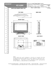
KE-42M1 SUPPLIED REMOTE RMY-1003 MDDDEIEOMSSDECCENRRLSII:PPIOTTNIIOOSNN::4M2"oPniltaosrm/RaecWeeivgear® POWER REQUIREMENTS:120VAC (W(WWEHHIGDDH))::T4:2 3/8 "x 32 5/8 " x 4 3/8" WEIGHT: 99 lbs 3 oz With TV Stand POWER CONSUMPTION: 60Hz 370 w 87 lbs 1 oz W/O TV Stand
KE-42M1 SUPPLIED REMOTE RMY-1003 MDDDEIEOMSSDECCENRRLSII:PPIOTTNIIOOSNN::4M2"oPniltaosrm/RaecWeeivgear® POWER REQUIREMENTS:120VAC (W(WWEHHIGDDH))::T4:2 3/8 "x 32 5/8 " x 4 3/8" WEIGHT: 99 lbs 3 oz With TV Stand POWER CONSUMPTION: 60Hz 370 w 87 lbs 1 oz W/O TV Stand
Operating Instructions (primary manual)
Page 4
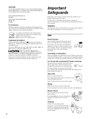
...the operating instructions or service manual. Do not defeat the safety purpose of electrical power supplied to have a suitable outlet installed. If it may cause electric shock. Wiring Unplug the AC power cord when wiring cables. Follow the instructions below: For the set with all ...or local power company. KE-42M1 SONY WALL-MOUNT BRACKET MODEL NO. SU-PW2 To Customers Sufficient expertise is covered with a three-wire grounding type plug (a plug having one way. Unplug the AC power plug and clean it may cause arcing and result in . This TV incorporates High-...
...the operating instructions or service manual. Do not defeat the safety purpose of electrical power supplied to have a suitable outlet installed. If it may cause electric shock. Wiring Unplug the AC power cord when wiring cables. Follow the instructions below: For the set with all ...or local power company. KE-42M1 SONY WALL-MOUNT BRACKET MODEL NO. SU-PW2 To Customers Sufficient expertise is covered with a three-wire grounding type plug (a plug having one way. Unplug the AC power plug and clean it may cause arcing and result in . This TV incorporates High-...
Operating Instructions (primary manual)
Page 8
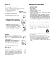
... manufacturer's instructions. 8) Do not install near water. 6) Clean only with dry cloth. 7) Do not block any heat sources such as power-supply cord or plug is used replacement parts specified by being walked on or pinched particularly at plugs, convenience receptacles, and the point where they exit...the set has been subject to excessive shock by the manufacturer that the set does not operate normally when following conditions: s When the power cord or plug is in safe operating condition, and to qualified service personnel. Adjust only those controls that produce heat. 9) Do not...
... manufacturer's instructions. 8) Do not install near water. 6) Clean only with dry cloth. 7) Do not block any heat sources such as power-supply cord or plug is used replacement parts specified by being walked on or pinched particularly at plugs, convenience receptacles, and the point where they exit...the set has been subject to excessive shock by the manufacturer that the set does not operate normally when following conditions: s When the power cord or plug is in safe operating condition, and to qualified service personnel. Adjust only those controls that produce heat. 9) Do not...
Operating Instructions (primary manual)
Page 11
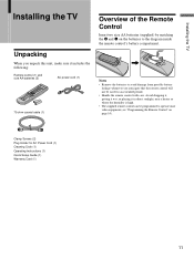
... the TV Installing the TV Unpacking When you anticipate that the remote control will not be programmed to the diagram inside the remote control's battery compartment. Avoid dropping it, getting it wet, or placing it includes the following: Remote control (1) and size AA batteries (2) AC power cord ...(1) 75-ohm coaxial cable (1) Overview of the Remote Control Insert two size AA batteries (supplied) by matching the e and E on the batteries to operate most video equipment (see "...
... the TV Installing the TV Unpacking When you anticipate that the remote control will not be programmed to the diagram inside the remote control's battery compartment. Avoid dropping it, getting it wet, or placing it includes the following: Remote control (1) and size AA batteries (2) AC power cord ...(1) 75-ohm coaxial cable (1) Overview of the Remote Control Insert two size AA batteries (supplied) by matching the e and E on the batteries to operate most video equipment (see "...

Operating Instructions (primary manual)
Page 18
When in 1 (Power on and off ) LED When lit, indicates that has S VIDEO. If the LED blinks continuously, this LED will open the drop-down panel of the timers is set , this may indicate the TV needs LED servicing (see page 77). 5 i Headphones jack Connects to your camcorder ...see page 48. 4 1 (Power) and Press 1 (Power) to the composite A/V output jacks on your TV, push up the panel door just under the mark until you hear a click, then the panel door will remain lit. If your headphones do not match the jack, use a suitable plug adaptor (not supplied). 6 S VIDEO IN 2 ...
When in 1 (Power on and off ) LED When lit, indicates that has S VIDEO. If the LED blinks continuously, this LED will open the drop-down panel of the timers is set , this may indicate the TV needs LED servicing (see page 77). 5 i Headphones jack Connects to your camcorder ...see page 48. 4 1 (Power) and Press 1 (Power) to the composite A/V output jacks on your TV, push up the panel door just under the mark until you hear a click, then the panel door will remain lit. If your headphones do not match the jack, use a suitable plug adaptor (not supplied). 6 S VIDEO IN 2 ...

Operating Instructions (primary manual)
Page 19
... connects to your VHF/UHF antenna or cable box. 3 AC IN Connects the supplied AC power cord. 4 S VIDEO IN 1/3 Connects to the composite A/V output jacks on the front panel of your VCR or other video component. Component video provides better picture quality than either...8 Jack Description 1 HDMI IN/L-AUDIO-R (HDMI IN 5) HDMI (High-Definition Multimedia Interface) provides an uncompressed, all-digital audio/video interface between this TV and any HDMI-equipped audio/video component, such as a center speaker. * "Dolby", "Pro Logic", and the double-D symbol are trademarks of your...
... connects to your VHF/UHF antenna or cable box. 3 AC IN Connects the supplied AC power cord. 4 S VIDEO IN 1/3 Connects to the composite A/V output jacks on the front panel of your VCR or other video component. Component video provides better picture quality than either...8 Jack Description 1 HDMI IN/L-AUDIO-R (HDMI IN 5) HDMI (High-Definition Multimedia Interface) provides an uncompressed, all-digital audio/video interface between this TV and any HDMI-equipped audio/video component, such as a center speaker. * "Dolby", "Pro Logic", and the double-D symbol are trademarks of your...
Operating Instructions (primary manual)
Page 22
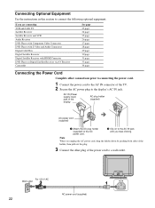
...of the holder, then pull out the plug. 3 Connect the other connections prior to connecting the power cord. 1 Connect the power cord to the AC IN connector of the TV. 2 Secure the AC power plug to a wall outlet. Connecting Optional Equipment Use the instructions in this section to connect the...page 33 page 34 page Connecting the Power Cord Complete other plug of the power cord to the display's AC IN jack. AC IN (Power supply input) jack of the display AC plug holder (supplied) AC power cord (supplied) 1 Attach the AC plug holder (supplied) to the AC power cord. 2 Clip on to the AC...
...of the holder, then pull out the plug. 3 Connect the other connections prior to connecting the power cord. 1 Connect the power cord to the AC IN connector of the TV. 2 Secure the AC power plug to a wall outlet. Connecting Optional Equipment Use the instructions in this section to connect the...page 33 page 34 page Connecting the Power Cord Complete other plug of the power cord to the display's AC IN jack. AC IN (Power supply input) jack of the display AC plug holder (supplied) AC power cord (supplied) 1 Attach the AC plug holder (supplied) to the AC power cord. 2 Clip on to the AC...
Operating Instructions (primary manual)
Page 23
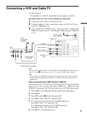
...4 Press V/v to select "Auto YC," then press . 5 To watch the pictures input from which the TV receives the input signal. Disconnect all power sources before making any connections. 1 Connect the CATV cable to the VCR's IN jack. 2 Using the supplied 75-ohm coaxial cable, connect the VCR's OUT jack to the... TV's VHF/UHF jack. 3 Using AUDIO and S VIDEO cables, connect the VCR's AUDIO and S ...
...4 Press V/v to select "Auto YC," then press . 5 To watch the pictures input from which the TV receives the input signal. Disconnect all power sources before making any connections. 1 Connect the CATV cable to the VCR's IN jack. 2 Using the supplied 75-ohm coaxial cable, connect the VCR's OUT jack to the... TV's VHF/UHF jack. 3 Using AUDIO and S VIDEO cables, connect the VCR's AUDIO and S ...

Operating Instructions (primary manual)
Page 24
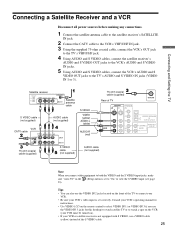
... your satellite receiver. • If your cable or antenna to view the S VIDEO input (see page 23). Connecting a Satellite Receiver Disconnect all power sources before making any connections. 1 Connect the satellite antenna cable to the satellite receiver's SATELLITE IN jack. 2 Using AUDIO and S VIDEO cables,... connect the satellite receiver's AUDIO and S VIDEO OUT jacks to the TV's AUDIO and S VIDEO IN jacks (VIDEO IN 1 or 3). 3 Connect the supplied 75-ohm coaxial cable from your satellite receiver is set to "On" to the TV's VHF/UHF jack. Tips • You can also use the VIDEO IN...
... your satellite receiver. • If your cable or antenna to view the S VIDEO input (see page 23). Connecting a Satellite Receiver Disconnect all power sources before making any connections. 1 Connect the satellite antenna cable to the satellite receiver's SATELLITE IN jack. 2 Using AUDIO and S VIDEO cables,... connect the satellite receiver's AUDIO and S VIDEO OUT jacks to the TV's AUDIO and S VIDEO IN jacks (VIDEO IN 1 or 3). 3 Connect the supplied 75-ohm coaxial cable from your satellite receiver is set to "On" to the TV's VHF/UHF jack. Tips • You can also use the VIDEO IN...
Operating Instructions (primary manual)
Page 25
... cable (not supplied) AUDIO cable (not supplied) Note When you use a VIDEO cable (yellow) instead of the TV to connect your VCR. • Be sure your VCR or satellite receiver is set correctly. Connecting and Setting the TV Connecting a Satellite Receiver and a VCR Disconnect all power sources before making any connections. 1 Connect the satellite antenna...
... cable (not supplied) AUDIO cable (not supplied) Note When you use a VIDEO cable (yellow) instead of the TV to connect your VCR. • Be sure your VCR or satellite receiver is set correctly. Connecting and Setting the TV Connecting a Satellite Receiver and a VCR Disconnect all power sources before making any connections. 1 Connect the satellite antenna...
Operating Instructions (primary manual)
Page 26
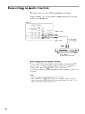
...control the volume output from "Off" to "On." Otherwise, the speaker volume may get too loud. 26 Connecting an Audio Receiver Disconnect all power sources before switching "Speaker" from your audio system, set to "Variable," "Speaker" is to "Off," check if the speaker volume is ...IN 180W (6 ) MAX L(MONO) AUDIO R AUDIO OUT (VAR/FIX) AUDIO-L (white) AUDIO-R (red) AUDIO cable (not supplied) Audio input Audio receiver (Compact AV system, etc.) When using the TV's remote control (see "Programming the Remote Control" on page 14), by setting "Audio Out" in the (Audio) menu is ...
...control the volume output from "Off" to "On." Otherwise, the speaker volume may get too loud. 26 Connecting an Audio Receiver Disconnect all power sources before switching "Speaker" from your audio system, set to "Variable," "Speaker" is to "Off," check if the speaker volume is ...IN 180W (6 ) MAX L(MONO) AUDIO R AUDIO OUT (VAR/FIX) AUDIO-L (white) AUDIO-R (red) AUDIO cable (not supplied) Audio input Audio receiver (Compact AV system, etc.) When using the TV's remote control (see "Programming the Remote Control" on page 14), by setting "Audio Out" in the (Audio) menu is ...
Operating Instructions (primary manual)
Page 27
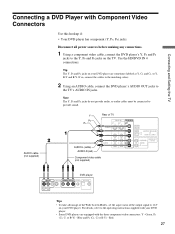
... cables to the matching colors. 2 Using an AUDIO cable, connect the DVD player's AUDIO OUT jacks to 16:9 on the TV. Note The Y, PB and PR jacks do not provide audio, so audio cables must be connected to the operating instructions supplied with Component Video Connectors ...Use this hookup if: • Your DVD player has component (Y, PB, PR) jacks. For details, refer to provide sound. Blue and PR (CR, Cr or R-Y) - Green, PB (CB, Cb or B-Y) - Disconnect all power sources before making any connections...
... cables to the matching colors. 2 Using an AUDIO cable, connect the DVD player's AUDIO OUT jacks to 16:9 on the TV. Note The Y, PB and PR jacks do not provide audio, so audio cables must be connected to the operating instructions supplied with Component Video Connectors ...Use this hookup if: • Your DVD player has component (Y, PB, PR) jacks. For details, refer to provide sound. Blue and PR (CR, Cr or R-Y) - Green, PB (CB, Cb or B-Y) - Disconnect all power sources before making any connections...

Operating Instructions (primary manual)
Page 28
...Tips • You can also use the connection described on your DVD player. Disconnect all power sources before making any connections. 1 Using an AUDIO cable, connect the DVD player's AUDIO OUT jacks to the TV's AUDIO IN jacks. 2 Using an S VIDEO cable, connect the DVD player's S... VIDEO OUT jack to the matching colors. If so, connect the cables to the TV's S VIDEO IN jack (VIDEO IN 1 or 3). S VIDEO cable (not supplied) AUDIO cable (not supplied) S VIDEO VIDEO (yellow) AUDIO-L (white) AUDIO-R (red) Rear of TV VIDEO IN 1 3 S VIDEO VIDEO L(MONO) AUDIO R HD...
...Tips • You can also use the connection described on your DVD player. Disconnect all power sources before making any connections. 1 Using an AUDIO cable, connect the DVD player's AUDIO OUT jacks to the TV's AUDIO IN jacks. 2 Using an S VIDEO cable, connect the DVD player's S... VIDEO OUT jack to the matching colors. If so, connect the cables to the TV's S VIDEO IN jack (VIDEO IN 1 or 3). S VIDEO cable (not supplied) AUDIO cable (not supplied) S VIDEO VIDEO (yellow) AUDIO-L (white) AUDIO-R (red) Rear of TV VIDEO IN 1 3 S VIDEO VIDEO L(MONO) AUDIO R HD...

Operating Instructions (primary manual)
Page 29
... video cable (not supplied) Y PB PR AUDIO-L (white) AUDIO-R (red) Rear of 852 dots × 480 lines. 2 Using an AUDIO cable, connect the Digital Cable Box's AUDIO OUT jacks to the Y, PB and PR jacks on the TV. Note that this TV displays all power sources before making any connections. 1 ...Using a component video cable, connect the Digital Cable Box's Y, PB and PR jacks to the TV's AUDIO IN jacks. Connecting and Setting the TV Connecting a Digital Cable Box Disconnect all ...
... video cable (not supplied) Y PB PR AUDIO-L (white) AUDIO-R (red) Rear of 852 dots × 480 lines. 2 Using an AUDIO cable, connect the Digital Cable Box's AUDIO OUT jacks to the Y, PB and PR jacks on the TV. Note that this TV displays all power sources before making any connections. 1 ...Using a component video cable, connect the Digital Cable Box's Y, PB and PR jacks to the TV's AUDIO IN jacks. Connecting and Setting the TV Connecting a Digital Cable Box Disconnect all ...

Operating Instructions (primary manual)
Page 30
...PR L AUDIO R CENTER SPEAKER IN 180W (6 ) MAX L(MONO) AUDIO R AUDIO OUT (VAR/FIX) Digital Satellite Receiver 30 Note that this TV displays all power sources before making any connections. 1 Using a component video cable, connect the Digital Satellite Receiver's Y, PB and PR jacks to the Y, PB and... PR jacks on the TV. AUDIO cable (not supplied) Component video cable (not supplied) Y PB PR AUDIO-L (white) AUDIO-R (red) Rear of 852 ...
...PR L AUDIO R CENTER SPEAKER IN 180W (6 ) MAX L(MONO) AUDIO R AUDIO OUT (VAR/FIX) Digital Satellite Receiver 30 Note that this TV displays all power sources before making any connections. 1 Using a component video cable, connect the Digital Satellite Receiver's Y, PB and PR jacks to the Y, PB and... PR jacks on the TV. AUDIO cable (not supplied) Component video cable (not supplied) Y PB PR AUDIO-L (white) AUDIO-R (red) Rear of 852 ...

Operating Instructions (primary manual)
Page 31
...power sources before making any connections. Tip The HDMI connector provides both video and audio signals, so it is not necessary to the TV's HDMI IN connector. Use the HDMI IN 5 connection. Using an HDMI cable (not supplied), connect the Digital Satellite Receiver's HDMI OUT connector to connect the audio cable. Rear of TV... R L AUDIO IN 5 IN VIDEO IN 1 3 S VIDEO VIDEO L(MONO) AUDIO R Digital Satellite Receiver HDMI cable (not supplied) (Continued) 31 Connecting and Setting the TV Connecting a Digital Satellite Receiver with HDMI...
...power sources before making any connections. Tip The HDMI connector provides both video and audio signals, so it is not necessary to the TV's HDMI IN connector. Use the HDMI IN 5 connection. Using an HDMI cable (not supplied), connect the Digital Satellite Receiver's HDMI OUT connector to connect the audio cable. Rear of TV... R L AUDIO IN 5 IN VIDEO IN 1 3 S VIDEO VIDEO L(MONO) AUDIO R Digital Satellite Receiver HDMI cable (not supplied) (Continued) 31 Connecting and Setting the TV Connecting a Digital Satellite Receiver with HDMI...

Operating Instructions (primary manual)
Page 33
... AV Receiver's OPTICAL IN jack. For more details, see "Using the Center Speaker Feature" on the TV. Disconnect all power sources before making any connections. 1 Using a SPEAKER cord, connect the TV's CENTER SPEAKER IN terminals to the AV Receiver's CENTER SPEAKER OUT terminals. 2 Using a component video cable... Y PB/CB PR/CR COMPONENT VIDEO OUT OPTICAL DIGITAL IN VIDEO 2 AV receiver AM FM 75 COAXIAL Optical digital cable (not supplied) When using the TV's speakers as the center speaker Using "Center Speaker Mode" in (Audio) menu, select the video input that is PCM/Dolby Digital...
... AV Receiver's OPTICAL IN jack. For more details, see "Using the Center Speaker Feature" on the TV. Disconnect all power sources before making any connections. 1 Using a SPEAKER cord, connect the TV's CENTER SPEAKER IN terminals to the AV Receiver's CENTER SPEAKER OUT terminals. 2 Using a component video cable... Y PB/CB PR/CR COMPONENT VIDEO OUT OPTICAL DIGITAL IN VIDEO 2 AV receiver AM FM 75 COAXIAL Optical digital cable (not supplied) When using the TV's speakers as the center speaker Using "Center Speaker Mode" in (Audio) menu, select the video input that is PCM/Dolby Digital...

Operating Instructions (primary manual)
Page 34
Using an A/V cable, connect the Camcorder's A/V OUT jack to connect your camcorder. Connecting a Camcorder Disconnect all power sources before making any connections. Tip You can also use the VIDEO 1 and 3 jacks located on the rear of TV S VIDEO (MONO) VIDEO L AUDIO R VIDEO IN 2 VIDEO (yellow) AUDIO-L (white) AUDIO-R (red) A/V cable (not supplied) A/V output 34 Front of the TV to the TV's AUDIO IN jacks and VIDEO IN jack (VIDEO IN 2).
Using an A/V cable, connect the Camcorder's A/V OUT jack to connect your camcorder. Connecting a Camcorder Disconnect all power sources before making any connections. Tip You can also use the VIDEO 1 and 3 jacks located on the rear of TV S VIDEO (MONO) VIDEO L AUDIO R VIDEO IN 2 VIDEO (yellow) AUDIO-L (white) AUDIO-R (red) A/V cable (not supplied) A/V output 34 Front of the TV to the TV's AUDIO IN jacks and VIDEO IN jack (VIDEO IN 2).
Operating Instructions (primary manual)
Page 52
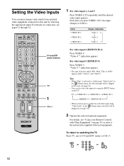
... "Using your Remote Controls with Other Equipment" on page 16, or refer to the instructions supplied with each video input using the INPUT button on the TV. "Video 4"* indication appears. Tips • When "Skip" is selected as follows. TV t VIDEO IN 1 t VIDEO IN 2 tVIDEO IN 3 R HDMI IN 5 T HD/DVD IN 4 T • ... using "Video Label" in the cycle (see page 53). 2 Operate the selected optional equipment. For video input 5 (HDMI IN 5) Press VIDEO 5. DVD/ SAT/ POWER MUTING VCR CABLE MODE PICTURE WIDE SLEEP DISPLAY FREEZE FAVORITES MENU TOP MENU 0-9 and ENT (enter) buttons F1 F2...
... "Using your Remote Controls with Other Equipment" on page 16, or refer to the instructions supplied with each video input using the INPUT button on the TV. "Video 4"* indication appears. Tips • When "Skip" is selected as follows. TV t VIDEO IN 1 t VIDEO IN 2 tVIDEO IN 3 R HDMI IN 5 T HD/DVD IN 4 T • ... using "Video Label" in the cycle (see page 53). 2 Operate the selected optional equipment. For video input 5 (HDMI IN 5) Press VIDEO 5. DVD/ SAT/ POWER MUTING VCR CABLE MODE PICTURE WIDE SLEEP DISPLAY FREEZE FAVORITES MENU TOP MENU 0-9 and ENT (enter) buttons F1 F2...

Operating Instructions (primary manual)
Page 78
... Press PICTURE to select the desired Picture Mode (page 42). • Make sure that the antenna is connected using the supplied 75-ohm coaxial cable. • Keep the antenna ... on the TV does not light in red, press 1 (Power) on the TV. • Point the remote control at the remote control sensor of the TV. • Install the TV away from fluorescent...color, you cannot select it is set to other connecting cords. • Do not use 300-ohm twin lead cables as interference may occur. • This is caused by feature of the Plasma Display Panel, and does not indicate a malfunction of the TV...
... Press PICTURE to select the desired Picture Mode (page 42). • Make sure that the antenna is connected using the supplied 75-ohm coaxial cable. • Keep the antenna ... on the TV does not light in red, press 1 (Power) on the TV. • Point the remote control at the remote control sensor of the TV. • Install the TV away from fluorescent...color, you cannot select it is set to other connecting cords. • Do not use 300-ohm twin lead cables as interference may occur. • This is caused by feature of the Plasma Display Panel, and does not indicate a malfunction of the TV...


