Operating Instructions
Page 3
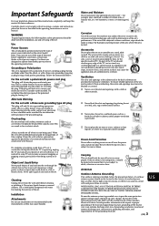
... the plug still fails to fit, contact your electrician to have a suitable outlet installed. If you are not sure of the type of electrical power supplied to your home, consult your dealer or service technician. When the set 's performance. Cleaning Unplug the set or described in cabinet, unless proper ...or other similar surface. This is grounded so as to provide some TV sets to make occasional snapping or popping sounds, particularly when being used. Do not defeat the safety purpose of the polarized plug by Sony for the specific model of any kind on the set from the ...
... the plug still fails to fit, contact your electrician to have a suitable outlet installed. If you are not sure of the type of electrical power supplied to your home, consult your dealer or service technician. When the set 's performance. Cleaning Unplug the set or described in cabinet, unless proper ...or other similar surface. This is grounded so as to provide some TV sets to make occasional snapping or popping sounds, particularly when being used. Do not defeat the safety purpose of the polarized plug by Sony for the specific model of any kind on the set from the ...
Operating Instructions
Page 6
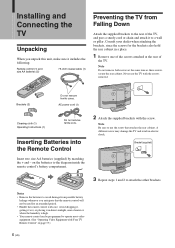
... programmed to a wall or pillar. AC power cord (1) Cleaning cloth (1) Operating Instructions (1) Do not remove ferrite core. Inserting Batteries into the Remote Control Insert two size AA batteries (supplied) by matching the + and - Brackets (2) Do not remove ferrite cores. Notes • Remove the batteries to use the TV with the screw. A different screw...
... programmed to a wall or pillar. AC power cord (1) Cleaning cloth (1) Operating Instructions (1) Do not remove ferrite core. Inserting Batteries into the Remote Control Insert two size AA batteries (supplied) by matching the + and - Brackets (2) Do not remove ferrite cores. Notes • Remove the batteries to use the TV with the screw. A different screw...
Operating Instructions
Page 9
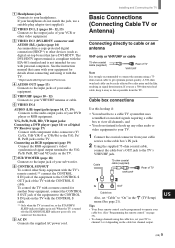
...) menu (See page 21). Cable box connections Use this function. 9 AC IN Connects the supplied AC power cord. Cable 75-ohm coaxial cable (supplied) VHF/UHF Rear of TV IN OUT Cable box Also, set your TV to your VCR or other video equipment. 3 VIDEO IN 3 (DVI-HDTV connector and AUDIO (R/L) ... to get optimum picture quality. If you cannot use a 300-ohm twin lead cable, keep it with the CONTROL S cable. Tips • Your Sony remote control can be programmed to operate your cable box. (See "Programming the remote control" on page 33). • To change channels using a...
...) menu (See page 21). Cable box connections Use this function. 9 AC IN Connects the supplied AC power cord. Cable 75-ohm coaxial cable (supplied) VHF/UHF Rear of TV IN OUT Cable box Also, set your TV to your VCR or other video equipment. 3 VIDEO IN 3 (DVI-HDTV connector and AUDIO (R/L) ... to get optimum picture quality. If you cannot use a 300-ohm twin lead cable, keep it with the CONTROL S cable. Tips • Your Sony remote control can be programmed to operate your cable box. (See "Programming the remote control" on page 33). • To change channels using a...
Operating Instructions
Page 10
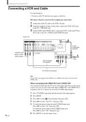
...S VIDEO input jack: Press V/v to exit the menu screen. Disconnect all power sources before making any connections. 1 Connect the cable TV cable to the VCR's IN jack. 2 Using the supplied 75-ohm coaxial cable, connect the VCR's OUT jack to the TV's VHF/UHF jack. 3 Using AUDIO and S VIDEO cables, connect the ...VCR's Audio and S Video OUT jacks to the TV's AUDIO and S VIDEO IN jacks....
...S VIDEO input jack: Press V/v to exit the menu screen. Disconnect all power sources before making any connections. 1 Connect the cable TV cable to the VCR's IN jack. 2 Using the supplied 75-ohm coaxial cable, connect the VCR's OUT jack to the TV's VHF/UHF jack. 3 Using AUDIO and S VIDEO cables, connect the ...VCR's Audio and S Video OUT jacks to the TV's AUDIO and S VIDEO IN jacks....
Operating Instructions
Page 11
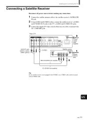
... the TV Disconnect all power sources before making any connections. 1 Connect the satellite antenna cable to the satellite receiver's SATELLITE IN jack. 2 Using AUDIO and S VIDEO cables, connect the satellite receiver's AUDIO and S VIDEO OUT jacks to the TV's VHF/UHF jack. Rear of TV VIDEO ...VIDEO (yellow) S VIDEO Satellite receiver Satellite antenna cable VMC-810S/820S (not supplied) YC-15V/30V (not supplied) Tip If your cable or antenna to the TV's AUDIO and S VIDEO IN jacks. 3 Connect the supplied 75-ohm coaxial cable from your satellite receiver is not equipped with S VIDEO...
... the TV Disconnect all power sources before making any connections. 1 Connect the satellite antenna cable to the satellite receiver's SATELLITE IN jack. 2 Using AUDIO and S VIDEO cables, connect the satellite receiver's AUDIO and S VIDEO OUT jacks to the TV's VHF/UHF jack. Rear of TV VIDEO ...VIDEO (yellow) S VIDEO Satellite receiver Satellite antenna cable VMC-810S/820S (not supplied) YC-15V/30V (not supplied) Tip If your cable or antenna to the TV's AUDIO and S VIDEO IN jacks. 3 Connect the supplied 75-ohm coaxial cable from your satellite receiver is not equipped with S VIDEO...
Operating Instructions
Page 12
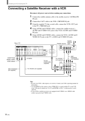
Installing and Connecting the TV Connecting a Satellite Receiver with a VCR Disconnect all power sources before making any connections. 1 Connect the satellite antenna cable to the satellite receiver's SATELLITE IN jack. 2 Connect the CATV cable to the VCR's VHF/UHF IN jack. 3 Using the supplied 75-ohm coaxial cable, connect the VCR's OUT jack to...
Installing and Connecting the TV Connecting a Satellite Receiver with a VCR Disconnect all power sources before making any connections. 1 Connect the satellite antenna cable to the satellite receiver's SATELLITE IN jack. 2 Connect the CATV cable to the VCR's VHF/UHF IN jack. 3 Using the supplied 75-ohm coaxial cable, connect the VCR's OUT jack to...
Operating Instructions
Page 13
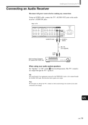
...system speakers Set "Speaker" to "Off" on the (Custom Setup) menu. Note Even though you change the TV's volume or other sound settings, the sound of TV VIDEO IN 1 R AUDIO L VIDEO S VIDEO VIDEO IN 2 COMPONENT VIDEO IN 1 AUDIO OUT R AUDIO...(Compact AV system DAV-C990, etc) Audio input RK-74A (not supplied) When using your audio system does not change. The TV's sound is not output through the AUDIO OUT jacks. US (US)... 13 Note that the video signal is also output through the TV's speakers. Using an AUDIO cable, connect the TV's AUDIO OUT jacks to the VIDEO IN 4 jacks is not ...
...system speakers Set "Speaker" to "Off" on the (Custom Setup) menu. Note Even though you change the TV's volume or other sound settings, the sound of TV VIDEO IN 1 R AUDIO L VIDEO S VIDEO VIDEO IN 2 COMPONENT VIDEO IN 1 AUDIO OUT R AUDIO...(Compact AV system DAV-C990, etc) Audio input RK-74A (not supplied) When using your audio system does not change. The TV's sound is not output through the AUDIO OUT jacks. US (US)... 13 Note that the video signal is also output through the TV's speakers. Using an AUDIO cable, connect the TV's AUDIO OUT jacks to the VIDEO IN 4 jacks is not ...

Operating Instructions
Page 14
...Y/G VHF/UHF AC IN RK-74A (not supplied) VMC-10HG (not supplied) DVD player 14 (US) Note Set "Video 4 Mode" to use if: • Your DVD player has component (Y, B-Y, R-Y) jacks. Be sure to "Y/PB/ PR" in the (Initial Setup) menu (see page 32). Tips • To take advantage of the... video connection. If so, connect the cables to the matching colors. 2 Using an AUDIO cable, connect the DVD player's AUDIO OUT jacks to the Y/G, PB/B and PR/R jacks on the TV. Use the VIDEO IN 4 connections. Disconnect all power sources before making any connections. 1 Using three separate component video...
...Y/G VHF/UHF AC IN RK-74A (not supplied) VMC-10HG (not supplied) DVD player 14 (US) Note Set "Video 4 Mode" to use if: • Your DVD player has component (Y, B-Y, R-Y) jacks. Be sure to "Y/PB/ PR" in the (Initial Setup) menu (see page 32). Tips • To take advantage of the... video connection. If so, connect the cables to the matching colors. 2 Using an AUDIO cable, connect the DVD player's AUDIO OUT jacks to the Y/G, PB/B and PR/R jacks on the TV. Use the VIDEO IN 4 connections. Disconnect all power sources before making any connections. 1 Using three separate component video...

Operating Instructions
Page 15
...your DVD player. Tips • To take advantage of the Wide Screen Modes, set "Auto YC" to the operating instructions supplied with S VIDEO, use the connection described on the remote to the TV's S VIDEO jack. For details, refer to "On" in the (Custom Setup) menu (see page 10). Use 0-9...-15V/30V (not supplied) DVD player Note To watch cable TV. • If your DVD player is not equipped with your DVD player. • Use TV/VIDEO on page 14. Rear of the S VIDEO cable. US (US) 15 Disconnect all power sources before making any connections. 1 Using an AUDIO cable, ...
...your DVD player. Tips • To take advantage of the Wide Screen Modes, set "Auto YC" to the operating instructions supplied with S VIDEO, use the connection described on the remote to the TV's S VIDEO jack. For details, refer to "On" in the (Custom Setup) menu (see page 10). Use 0-9...-15V/30V (not supplied) DVD player Note To watch cable TV. • If your DVD player is not equipped with your DVD player. • Use TV/VIDEO on page 14. Rear of the S VIDEO cable. US (US) 15 Disconnect all power sources before making any connections. 1 Using an AUDIO cable, ...
Operating Instructions
Page 16
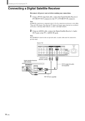
...) DVI-D single link cable (not supplied) RK-74A (not supplied) 16 (US) Rear of 852 dots × 1024 lines (KE-32TS2U), or 1024 × 1024 (KE-42TS2U). 2 Using an AUDIO cable, connect the Digital Satellite Receiver's Audio OUT jacks to the TV's DVI-HDTV IN connector. Note that this TV displays all power sources before making any connections...
...) DVI-D single link cable (not supplied) RK-74A (not supplied) 16 (US) Rear of 852 dots × 1024 lines (KE-32TS2U), or 1024 × 1024 (KE-42TS2U). 2 Using an AUDIO cable, connect the Digital Satellite Receiver's Audio OUT jacks to the TV's DVI-HDTV IN connector. Note that this TV displays all power sources before making any connections...
Operating Instructions
Page 17
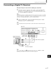
...PR/R jacks on the Digital TV Set-top box you connect (see page 32). Connecting a Digital TV Receiver Installing and Connecting the TV Disconnect all format types of 852 dots × 1024 lines (KE-32TS2U), or 1024 × 1024 (KE-42TS2U). 2 Using an AUDIO cable, connect the Digital TV Set-top box's Audio OUT... provide audio, so audio cables must be connected to the TV's AUDIO IN jacks. US (US) 17 Note that this TV displays all power sources before making any connections. 1 Using three separate component video cables, connect the Digital TV Set-top box's Y, PB and PR jacks to view ...
...PR/R jacks on the Digital TV Set-top box you connect (see page 32). Connecting a Digital TV Receiver Installing and Connecting the TV Disconnect all format types of 852 dots × 1024 lines (KE-32TS2U), or 1024 × 1024 (KE-42TS2U). 2 Using an AUDIO cable, connect the Digital TV Set-top box's Audio OUT... provide audio, so audio cables must be connected to the TV's AUDIO IN jacks. US (US) 17 Note that this TV displays all power sources before making any connections. 1 Using three separate component video cables, connect the Digital TV Set-top box's Y, PB and PR jacks to view ...
Operating Instructions
Page 18
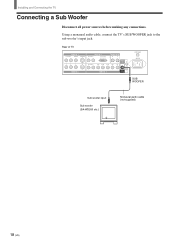
Installing and Connecting the TV Connecting a Sub Woofer Disconnect all power sources before making any connections. Using a monaural audio cable, connect the TV's SUB WOOFER jack to the sub woofer's input jack. Rear of TV VIDEO IN 1 R AUDIO L VIDEO S VIDEO VIDEO IN 2 VIDEO IN 3 R AUDIO L DVI-HDTV AUDIO OUT R L R AUDIO L Y/G PB/B PR/R HD CONTROL S IN VD OUT VIDEO IN 4 SUB WOOFER VHF/UHF AC IN SUB WOOFER Sub woofer input Sub woofer (SA-WD200 etc.) Monaural audio cable (not supplied) 18 (US)
Installing and Connecting the TV Connecting a Sub Woofer Disconnect all power sources before making any connections. Using a monaural audio cable, connect the TV's SUB WOOFER jack to the sub woofer's input jack. Rear of TV VIDEO IN 1 R AUDIO L VIDEO S VIDEO VIDEO IN 2 VIDEO IN 3 R AUDIO L DVI-HDTV AUDIO OUT R L R AUDIO L Y/G PB/B PR/R HD CONTROL S IN VD OUT VIDEO IN 4 SUB WOOFER VHF/UHF AC IN SUB WOOFER Sub woofer input Sub woofer (SA-WD200 etc.) Monaural audio cable (not supplied) 18 (US)
Operating Instructions
Page 32
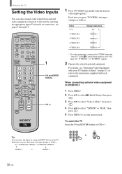
... optional equipment. Tip You can enjoy images (and sound) from optional video equipment connected to the instructions supplied with each equipment. Each time you press the button, the input changes as follows: Select • TV • VIDEO IN 1 • VIDEO IN 2 • VIDEO IN 3 • VIDEO IN...CH +/-. 123 CH 456 or 789 ENTER 0 32 (US) MUTING POWER VCR/DVD SAT/CABLE TV SYSTEM FUNCTION OFF VCR/DVD SAT/CABLE TV SLEEP PICTURE MODE WIDE MODE DISPLAY TV/VIDEO 123 456 7 JUMP FAVORITES 89 ENTER 0 MTS/SAP TV/SAT GUIDE POWER SAVING VOL MENU CH CODE SET 1 0-9 ...
... optional equipment. Tip You can enjoy images (and sound) from optional video equipment connected to the instructions supplied with each equipment. Each time you press the button, the input changes as follows: Select • TV • VIDEO IN 1 • VIDEO IN 2 • VIDEO IN 3 • VIDEO IN...CH +/-. 123 CH 456 or 789 ENTER 0 32 (US) MUTING POWER VCR/DVD SAT/CABLE TV SYSTEM FUNCTION OFF VCR/DVD SAT/CABLE TV SLEEP PICTURE MODE WIDE MODE DISPLAY TV/VIDEO 123 456 7 JUMP FAVORITES 89 ENTER 0 MTS/SAP TV/SAT GUIDE POWER SAVING VOL MENU CH CODE SET 1 0-9 ...
Operating Instructions
Page 59
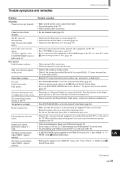
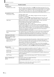
... connection between the optional video equipment and the TV. • Press TV/VIDEO on the remote (page 32). • If you set the POWER SAVING function to "Reduce," the picture may occur...and the TV to avoid noise. • Avoid installing your VCR away from noise sources such as interference may become dimmer (page 28). • The picture of a flat panel display is...supplied 75-ohm coaxial cable. • Keep the antenna cable away from other connecting cords. • Do not use , 1-2 years at the seaside) • Keep the TV away from the TV. • Leave a space of the TV. Color...
... connection between the optional video equipment and the TV. • Press TV/VIDEO on the remote (page 32). • If you set the POWER SAVING function to "Reduce," the picture may occur...and the TV to avoid noise. • Avoid installing your VCR away from noise sources such as interference may become dimmer (page 28). • The picture of a flat panel display is...supplied 75-ohm coaxial cable. • Keep the antenna cable away from other connecting cords. • Do not use , 1-2 years at the seaside) • Keep the TV away from the TV. • Leave a space of the TV. Color...
Operating Instructions
Page 60
... the TV's speakers regardless of the TV. • Install the TV away from the screen (page 23). • Disconnect your headphones. • Set "Speaker" to "On" in a pale color, you... period of the batteries. • If the STANDBY/SLEEP indicator on the TV does not light in red, press POWER on . This does not indicate a malfunction. • The batteries could be... using the supplied 75-ohm coaxial cable. • Keep the antenna cable away from other than infrared cordless headphones. Additional Information Problem Moving pictures. No sound./Noisy sound. The TV fan noise ...
... the TV's speakers regardless of the TV. • Install the TV away from the screen (page 23). • Disconnect your headphones. • Set "Speaker" to "On" in a pale color, you... period of the batteries. • If the STANDBY/SLEEP indicator on the TV does not light in red, press POWER on . This does not indicate a malfunction. • The batteries could be... using the supplied 75-ohm coaxial cable. • Keep the antenna cable away from other than infrared cordless headphones. Additional Information Problem Moving pictures. No sound./Noisy sound. The TV fan noise ...
Operating Instructions
Page 61
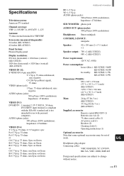
... TV standard Channel coverage: VHF: 2-13/UHF: 14-69/CATV: 1-125 Antenna: 75 ohm external terminal for VHF/UHF Screen size (measured diagonally): 32 inches (KE-32TS2U) 42 inches (KE-42TS2U) Panel System: Plasma Display panel Display resolution: 852 dots (horizontal) × 1024 lines (vertical) (KE-32TS2U...5/8 × 30 1/8 × 5 inch) (KE-42TS2U) Mass: 26 kg (57 lbs 3 oz.) (KE-32TS2U) 37.5 kg (82 lbs 7 oz.) (KE-42TS2U) Supplied accessories Remote control RM-928Y (1) Batteries size AA (2) 75-ohm coaxial cable (1) AC power cord (1) Brackets (2) Cleaning cloth (1) Operating instructions (1) ...
... TV standard Channel coverage: VHF: 2-13/UHF: 14-69/CATV: 1-125 Antenna: 75 ohm external terminal for VHF/UHF Screen size (measured diagonally): 32 inches (KE-32TS2U) 42 inches (KE-42TS2U) Panel System: Plasma Display panel Display resolution: 852 dots (horizontal) × 1024 lines (vertical) (KE-32TS2U...5/8 × 30 1/8 × 5 inch) (KE-42TS2U) Mass: 26 kg (57 lbs 3 oz.) (KE-32TS2U) 37.5 kg (82 lbs 7 oz.) (KE-42TS2U) Supplied accessories Remote control RM-928Y (1) Batteries size AA (2) 75-ohm coaxial cable (1) AC power cord (1) Brackets (2) Cleaning cloth (1) Operating instructions (1) ...


