
Child Safety: It Makes A Difference Where Your TV Stands
Page 1
.... 6 Remember that is large enough to support the weight of your television (and other electronic components). 2 Use appropriate angle braces, straps and anchors to secure your home. As a result, TV sets may cause unnecessary injury. Use the appropriate furniture that children can become excited while watching a program and can potentially push or pull...
.... 6 Remember that is large enough to support the weight of your television (and other electronic components). 2 Use appropriate angle braces, straps and anchors to secure your home. As a result, TV sets may cause unnecessary injury. Use the appropriate furniture that children can become excited while watching a program and can potentially push or pull...
Operating Instructions
Page 2
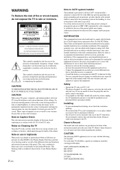
... than 1900m or 6248 feet (air pressure less than private viewing of programs broadcast on , the user is connected. - KE-32TS2U KE-42TS2U TV STAND MODEL NO.: SU-TS1U SONY ELECTRONICS INC. Note on 120 V AC. - These limits are cautioned that interference will not occur in accordance with other ...with §15.119 of the FCC rules. Never use in highlands When used in a particular installation. This is not considered a defect and is intended to alert the user to rain or moisture. If this Plasma Display Panel may cause harmful interference with the limits for help. Increase...
... than 1900m or 6248 feet (air pressure less than private viewing of programs broadcast on , the user is connected. - KE-32TS2U KE-42TS2U TV STAND MODEL NO.: SU-TS1U SONY ELECTRONICS INC. Note on 120 V AC. - These limits are cautioned that interference will not occur in accordance with other ...with §15.119 of the FCC rules. Never use in highlands When used in a particular installation. This is not considered a defect and is intended to alert the user to rain or moisture. If this Plasma Display Panel may cause harmful interference with the limits for help. Increase...
Operating Instructions
Page 3
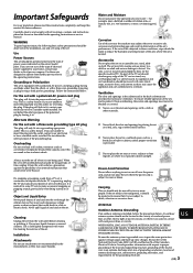
... having one way. Accessories Do not place the set is continuous or frequent while the TV is left unattended and unused for the grounding electrode. 3 (US) Carrying This set should be moved by Sony for cleaning the exterior of any overhanging edge is provided. US WHEN INSTALLING AN OUTDOOR ...table or shelf. Be sure the antenna system is exposed to reduce the humidity and temperature of the TV set should not be taken to direct sunlight. Water and Moisture Do not use liquid cleaners or aerosol cleaners. To ensure reliable operation of the set to excessive salt, corrosion and...
... having one way. Accessories Do not place the set is continuous or frequent while the TV is left unattended and unused for the grounding electrode. 3 (US) Carrying This set should be moved by Sony for cleaning the exterior of any overhanging edge is provided. US WHEN INSTALLING AN OUTDOOR ...table or shelf. Be sure the antenna system is exposed to reduce the humidity and temperature of the TV set should not be taken to direct sunlight. Water and Moisture Do not use liquid cleaners or aerosol cleaners. To ensure reliable operation of the set to excessive salt, corrosion and...
Operating Instructions
Page 4
...s If the set . Improper adjustment of other controls may result in performance, it from tip-over. Replacement Parts When replacement parts are required, be used. Service Damage Requiring Service Unplug the set . Ask a qualified service technician to dispose of the set has been exposed to rain or water. A... grounding type plug has two blades and a third grounding prong. s If the set reaches the end of its useful life, improper disposal could result in wire Power service grounding electrode system (NEC Art 250 Part H) Lightning For added protection for this television...
...s If the set . Improper adjustment of other controls may result in performance, it from tip-over. Replacement Parts When replacement parts are required, be used. Service Damage Requiring Service Unplug the set . Ask a qualified service technician to dispose of the set has been exposed to rain or water. A... grounding type plug has two blades and a third grounding prong. s If the set reaches the end of its useful life, improper disposal could result in wire Power service grounding electrode system (NEC Art 250 Part H) Lightning For added protection for this television...
Operating Instructions
Page 5
... Saving the Power Consumption 28 Using the Wide Screen Mode 29 Changing the Wide Screen Mode automatically 29 Changing the Wide Screen Mode manually 30 Changing the Wide Setup 30 Setting the Video Inputs 32 Operating Video Equipment with Your TV Remote Control 33 Programming the... remote control 33 Operating optional equipment 35 Using Favorite Channels 36 Setting your favorite channels 36 Watching Favorite Channel 37 Adjusting...
... Saving the Power Consumption 28 Using the Wide Screen Mode 29 Changing the Wide Screen Mode automatically 29 Changing the Wide Screen Mode manually 30 Changing the Wide Setup 30 Setting the Video Inputs 32 Operating Video Equipment with Your TV Remote Control 33 Programming the... remote control 33 Operating optional equipment 35 Using Favorite Channels 36 Setting your favorite channels 36 Watching Favorite Channel 37 Adjusting...
Operating Instructions
Page 6
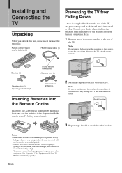
...Notes • Remove the batteries to avoid damage from Falling Down Attach the supplied brackets to the rear of the TV. Installing and Connecting the TV Installing and Connecting the TV Unpacking When you unpack this unit, make sure it includes the following: Remote control (1) and size AA batteries (2)...diagram inside the remote control's battery compartment. 2 Attach the supplied brackets with Your TV Remote Control" on the batteries to use the TV with care. Note Do not remove both screws at the rear of the TV, and pass a sturdy cord or chain and attach it to a wall or pillar...
...Notes • Remove the batteries to avoid damage from Falling Down Attach the supplied brackets to the rear of the TV. Installing and Connecting the TV Installing and Connecting the TV Unpacking When you unpack this unit, make sure it includes the following: Remote control (1) and size AA batteries (2)...diagram inside the remote control's battery compartment. 2 Attach the supplied brackets with Your TV Remote Control" on the batteries to use the TV with care. Note Do not remove both screws at the rear of the TV, and pass a sturdy cord or chain and attach it to a wall or pillar...
Operating Instructions
Page 7
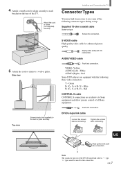
... three video connectors: Y - AUDIO/VIDEO cable Push into connection. Red Some DVD players are exclusive to use some of the TV. Push into connection. Installing and Connecting the TV Connector Types You may find it necessary to Sony equipment and allow greater control of the DVI-D single link cable is "-" type. Blue PR (CR...
... three video connectors: Y - AUDIO/VIDEO cable Push into connection. Red Some DVD players are exclusive to use some of the TV. Push into connection. Installing and Connecting the TV Connector Types You may find it necessary to Sony equipment and allow greater control of the DVI-D single link cable is "-" type. Blue PR (CR...
Operating Instructions
Page 9
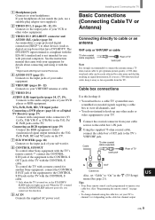
...intend to hook up in signal deterioration. To control the TV with a remote control for another Sony equipment, connect the CONTROL S OUT jack of the equipment to the CONTROL S IN jack on page 33). • To change channels using the cable box, set your VCR or other video equipment....output. Tips • Your Sony remote control can be programmed to operate your cable box. (See "Programming the remote control" on the TV with the CONTROL S cable. ** Only when the TV is not intended for details about connecting and using a 75ohm coaxial cable to your TV. 1 Connect the coaxial ...
...intend to hook up in signal deterioration. To control the TV with a remote control for another Sony equipment, connect the CONTROL S OUT jack of the equipment to the CONTROL S IN jack on page 33). • To change channels using the cable box, set your VCR or other video equipment....output. Tips • Your Sony remote control can be programmed to operate your cable box. (See "Programming the remote control" on the TV with the CONTROL S cable. ** Only when the TV is not intended for details about connecting and using a 75ohm coaxial cable to your TV. 1 Connect the coaxial ...
Operating Instructions
Page 10
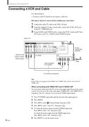
...4 Press V/v to exit the menu screen. The TV is not equipped with S VIDEO, use a VIDEO cable (yellow) instead of the S VIDEO cable. Disconnect all power sources before making any connections. 1 Connect the cable TV cable to the VCR's IN jack. 2 Using the supplied 75-ohm coaxial cable, connect the VCR...'s OUT jack to the TV's VHF/UHF jack. 3 Using AUDIO and S VIDEO cables, connect the VCR's Audio and S Video OUT...
...4 Press V/v to exit the menu screen. The TV is not equipped with S VIDEO, use a VIDEO cable (yellow) instead of the S VIDEO cable. Disconnect all power sources before making any connections. 1 Connect the cable TV cable to the VCR's IN jack. 2 Using the supplied 75-ohm coaxial cable, connect the VCR...'s OUT jack to the TV's VHF/UHF jack. 3 Using AUDIO and S VIDEO cables, connect the VCR's Audio and S Video OUT...
Operating Instructions
Page 11
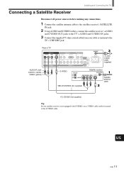
...any connections. 1 Connect the satellite antenna cable to the satellite receiver's SATELLITE IN jack. 2 Using AUDIO and S VIDEO cables, connect the satellite receiver's AUDIO and S VIDEO OUT jacks to the TV's AUDIO and S VIDEO IN jacks. 3 Connect the supplied 75-ohm coaxial cable from your ...satellite receiver is not equipped with S VIDEO, use a VIDEO cable (yellow) instead of TV VIDEO IN 1 R AUDIO L VIDEO S VIDEO VIDEO IN 2 VIDEO IN 3 R AUDIO L DVI-HDTV AUDIO OUT R L R AUDIO L Y/G PB/B PR/R HD CONTROL S ...
...any connections. 1 Connect the satellite antenna cable to the satellite receiver's SATELLITE IN jack. 2 Using AUDIO and S VIDEO cables, connect the satellite receiver's AUDIO and S VIDEO OUT jacks to the TV's AUDIO and S VIDEO IN jacks. 3 Connect the supplied 75-ohm coaxial cable from your ...satellite receiver is not equipped with S VIDEO, use a VIDEO cable (yellow) instead of TV VIDEO IN 1 R AUDIO L VIDEO S VIDEO VIDEO IN 2 VIDEO IN 3 R AUDIO L DVI-HDTV AUDIO OUT R L R AUDIO L Y/G PB/B PR/R HD CONTROL S ...
Operating Instructions
Page 12
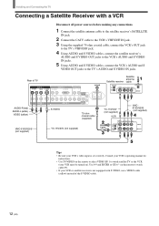
... the VCR (your VCR or satellite receiver is set correctly. on ). Installing and Connecting the TV Connecting a Satellite Receiver with S VIDEO, use a VIDEO cable (yellow) instead of TV VIDEO IN 1 R AUDIO L VIDEO S VIDEO VIDEO IN 2 VIDEO IN 3 R AUDIO L DVI-HDTV AUDIO OUT R L R AUDIO L Y/G PB/B PR/R HD CONTROL S...SATELLITE IN jack. 2 Connect the CATV cable to the VCR's VHF/UHF IN jack. 3 Using the supplied 75-ohm coaxial cable, connect the VCR's OUT jack to the TV's VHF/UHF jack. 4 Using AUDIO and S VIDEO cables, connect the satellite receiver's AUDIO and S VIDEO OUT jacks to the...
... the VCR (your VCR or satellite receiver is set correctly. on ). Installing and Connecting the TV Connecting a Satellite Receiver with S VIDEO, use a VIDEO cable (yellow) instead of TV VIDEO IN 1 R AUDIO L VIDEO S VIDEO VIDEO IN 2 VIDEO IN 3 R AUDIO L DVI-HDTV AUDIO OUT R L R AUDIO L Y/G PB/B PR/R HD CONTROL S...SATELLITE IN jack. 2 Connect the CATV cable to the VCR's VHF/UHF IN jack. 3 Using the supplied 75-ohm coaxial cable, connect the VCR's OUT jack to the TV's VHF/UHF jack. 4 Using AUDIO and S VIDEO cables, connect the satellite receiver's AUDIO and S VIDEO OUT jacks to the...
Operating Instructions
Page 13
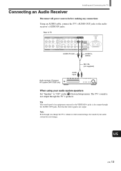
Tip The sound signal of an equipment connected to the VIDEO IN 4 jacks is also output through the TV's speakers. Note Even though you change the TV's volume or other sound settings, the sound of TV VIDEO IN 1 R AUDIO L VIDEO S VIDEO VIDEO IN 2 COMPONENT VIDEO IN 1 AUDIO OUT R AUDIO L Y PB ... not output through the AUDIO OUT jacks. Using an AUDIO cable, connect the TV's AUDIO OUT jacks to "Off" on the (Custom Setup) menu. The TV's sound is not output. Connecting an Audio Receiver Installing and Connecting the TV Disconnect all power sources before making any connections...
Tip The sound signal of an equipment connected to the VIDEO IN 4 jacks is also output through the TV's speakers. Note Even though you change the TV's volume or other sound settings, the sound of TV VIDEO IN 1 R AUDIO L VIDEO S VIDEO VIDEO IN 2 COMPONENT VIDEO IN 1 AUDIO OUT R AUDIO L Y PB ... not output through the AUDIO OUT jacks. Using an AUDIO cable, connect the TV's AUDIO OUT jacks to "Off" on the (Custom Setup) menu. The TV's sound is not output. Connecting an Audio Receiver Installing and Connecting the TV Disconnect all power sources before making any connections...

Operating Instructions
Page 14
...to "Y/PB/ PR" in the (Initial Setup) menu (see page 32). Rear of inputs that you used for the video connection. Tip The Y, B-Y and R-Y jacks on the TV. If so, connect the cables to the matching colors. 2 Using an AUDIO cable, connect the DVD player's AUDIO OUT jacks to ...the operating instructions supplied with your DVD player. Disconnect all power sources before making any connections. 1 Using three separate component video cables, connect...
...to "Y/PB/ PR" in the (Initial Setup) menu (see page 32). Rear of inputs that you used for the video connection. Tip The Y, B-Y and R-Y jacks on the TV. If so, connect the cables to the matching colors. 2 Using an AUDIO cable, connect the DVD player's AUDIO OUT jacks to ...the operating instructions supplied with your DVD player. Disconnect all power sources before making any connections. 1 Using three separate component video cables, connect...

Operating Instructions
Page 15
...the VCR and DVD player inputs. For details, refer to the operating instructions supplied with your DVD player. • Use TV/VIDEO on the remote to watch the pictures input from the S VIDEO input jack, set the TV's aspect ratio to "On" in the (Custom Setup) menu (see page 10). US (US) 15... Use 0-9 and ENTER or CH +/- Installing and Connecting the TV Connecting a DVD Player with S VIDEO, use a VIDEO cable (yellow) instead of the S VIDEO cable. Rear of the Wide Screen Modes, set "Auto YC" to 16:9 on page 14....
...the VCR and DVD player inputs. For details, refer to the operating instructions supplied with your DVD player. • Use TV/VIDEO on the remote to watch the pictures input from the S VIDEO input jack, set the TV's aspect ratio to "On" in the (Custom Setup) menu (see page 10). US (US) 15... Use 0-9 and ENTER or CH +/- Installing and Connecting the TV Connecting a DVD Player with S VIDEO, use a VIDEO cable (yellow) instead of the S VIDEO cable. Rear of the Wide Screen Modes, set "Auto YC" to 16:9 on page 14....
Operating Instructions
Page 16
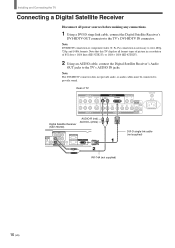
...-74A (not supplied) 16 (US) Rear of 852 dots × 1024 lines (KE-32TS2U), or 1024 × 1024 (KE-42TS2U). 2 Using an AUDIO cable, connect the Digital Satellite Receiver's Audio OUT jacks to the TV's AUDIO IN jacks. Installing and Connecting the TV Connecting a Digital Satellite Receiver Disconnect all format types of picture in a resolution of...
...-74A (not supplied) 16 (US) Rear of 852 dots × 1024 lines (KE-32TS2U), or 1024 × 1024 (KE-42TS2U). 2 Using an AUDIO cable, connect the Digital Satellite Receiver's Audio OUT jacks to the TV's AUDIO IN jacks. Installing and Connecting the TV Connecting a Digital Satellite Receiver Disconnect all format types of picture in a resolution of...
Operating Instructions
Page 17
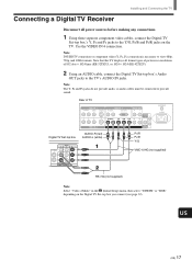
... you connect (see page 32). Connecting a Digital TV Receiver Installing and Connecting the TV Disconnect all format types of 852 dots × 1024 lines (KE-32TS2U), or 1024 × 1024 (KE-42TS2U). 2 Using an AUDIO cable, connect the Digital TV Set-top box's Audio OUT jacks to the TV's AUDIO IN jacks. Rear of TV Digital TV Set-top box VIDEO...
... you connect (see page 32). Connecting a Digital TV Receiver Installing and Connecting the TV Disconnect all format types of 852 dots × 1024 lines (KE-32TS2U), or 1024 × 1024 (KE-42TS2U). 2 Using an AUDIO cable, connect the Digital TV Set-top box's Audio OUT jacks to the TV's AUDIO IN jacks. Rear of TV Digital TV Set-top box VIDEO...
Operating Instructions
Page 18
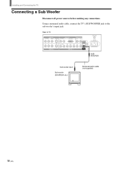
Rear of TV VIDEO IN 1 R AUDIO L VIDEO S VIDEO VIDEO IN 2 VIDEO IN 3 R AUDIO L DVI-HDTV AUDIO OUT R L R AUDIO L Y/G PB/B PR/R HD CONTROL S IN VD OUT VIDEO IN 4 SUB WOOFER VHF/UHF AC IN SUB WOOFER Sub woofer input Sub woofer (SA-WD200 etc.) Monaural audio cable (not supplied) 18 (US) Using a monaural audio cable, connect the TV's SUB WOOFER jack to the sub woofer's input jack. Installing and Connecting the TV Connecting a Sub Woofer Disconnect all power sources before making any connections.
Rear of TV VIDEO IN 1 R AUDIO L VIDEO S VIDEO VIDEO IN 2 VIDEO IN 3 R AUDIO L DVI-HDTV AUDIO OUT R L R AUDIO L Y/G PB/B PR/R HD CONTROL S IN VD OUT VIDEO IN 4 SUB WOOFER VHF/UHF AC IN SUB WOOFER Sub woofer input Sub woofer (SA-WD200 etc.) Monaural audio cable (not supplied) 18 (US) Using a monaural audio cable, connect the TV's SUB WOOFER jack to the sub woofer's input jack. Installing and Connecting the TV Connecting a Sub Woofer Disconnect all power sources before making any connections.

Operating Instructions
Page 19
... RGB cable, connect the RGB equipment's video/synchronized signal output terminal to the TV's AUDIO IN jacks. Rear of inputs that you used for the video connection. Be sure to use the same row of TV VIDEO IN 1 R AUDIO L VIDEO S VIDEO VIDEO IN 2 VIDEO IN 3 R AUDIO L DVI-HDTV AUDIO OUT... R L R AUDIO L Y/G PB/B PR/R HD CONTROL S IN VD OUT VIDEO IN 4 SUB WOOFER RGB equipment VHF/UHF AC IN Note Set "Video 4 Mode" to "RGB" in the (Initial Setup) menu (see page 32...
... RGB cable, connect the RGB equipment's video/synchronized signal output terminal to the TV's AUDIO IN jacks. Rear of inputs that you used for the video connection. Be sure to use the same row of TV VIDEO IN 1 R AUDIO L VIDEO S VIDEO VIDEO IN 2 VIDEO IN 3 R AUDIO L DVI-HDTV AUDIO OUT... R L R AUDIO L Y/G PB/B PR/R HD CONTROL S IN VD OUT VIDEO IN 4 SUB WOOFER RGB equipment VHF/UHF AC IN Note Set "Video 4 Mode" to "RGB" in the (Initial Setup) menu (see page 32...
Operating Instructions
Page 20
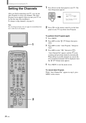
...CH- [ [ First please connect cable/antenna 2 Press CH+ on the remote control or on the front panel of your TV. Note The Auto Program feature does not apply for an installation that uses a cable box for the first time after installing it. When all channels. 1 Press Power on the front... panel of your TV to perform Auto Program. 1 MUTING POWER VCR/DVD SAT/CABLE TV SYSTEM FUNCTION OFF VCR/DVD SAT/CABLE TV SLEEP PICTURE MODE WIDE MODE DISPLAY TV/VIDEO ...
...CH- [ [ First please connect cable/antenna 2 Press CH+ on the remote control or on the front panel of your TV. Note The Auto Program feature does not apply for an installation that uses a cable box for the first time after installing it. When all channels. 1 Press Power on the front... panel of your TV to perform Auto Program. 1 MUTING POWER VCR/DVD SAT/CABLE TV SYSTEM FUNCTION OFF VCR/DVD SAT/CABLE TV SLEEP PICTURE MODE WIDE MODE DISPLAY TV/VIDEO ...
Operating Instructions
Page 21
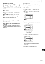
... skipped channel, select "Add." 6 Press MENU to a cable TV company. When you have a cable box or satellite receiver connected The Channel Fix feature is useful when you want to select "Skip," then press . Note that cable TV cannot be received in some areas. buttons. 1 Press MENU.... 2 Press V/v to select (TV Setup), then press . 3 Press V/v to select "On," then press ....
... skipped channel, select "Add." 6 Press MENU to a cable TV company. When you have a cable box or satellite receiver connected The Channel Fix feature is useful when you want to select "Skip," then press . Note that cable TV cannot be received in some areas. buttons. 1 Press MENU.... 2 Press V/v to select (TV Setup), then press . 3 Press V/v to select "On," then press ....


