
Child Safety: It Makes A Difference Where Your TV Stands
Page 1
... television and consumer electronics furniture manufacturers to advocate children's safety and educate customers and their families about television safety. As a result, TV sets may fall over . 7 Share our safety message on this hidden hazard of the home with your family and friends. The Consumer...entertainment enjoyable and safe. Use the appropriate furniture that children can become excited while watching a program and can potentially push or pull a TV over and may pique the children's curiosity. 6 Remember that is a growing trend, and larger televisions are popular purchases and are ...
... television and consumer electronics furniture manufacturers to advocate children's safety and educate customers and their families about television safety. As a result, TV sets may fall over . 7 Share our safety message on this hidden hazard of the home with your family and friends. The Consumer...entertainment enjoyable and safe. Use the appropriate furniture that children can become excited while watching a program and can potentially push or pull a TV over and may pique the children's curiosity. 6 Remember that is a growing trend, and larger televisions are popular purchases and are ...

Operating Instructions
Page 1
4-091-567-12 (1) Flat Panel Color TV KE-32TS2U/KE-42TS2U KE-32TS2U KE-42TS2U © 2002 Sony Corporation US FR Operating Instructions Mode d'emploi Manual de instrucciones ES
4-091-567-12 (1) Flat Panel Color TV KE-32TS2U/KE-42TS2U KE-32TS2U KE-42TS2U © 2002 Sony Corporation US FR Operating Instructions Mode d'emploi Manual de instrucciones ES
Operating Instructions
Page 2
... any changes or modifications not expressly approved in this manual could cause damage to correct the interference by the Limited Warranty. If any Plasma Display Panel. 2 (US) Note to CATV system installer This reminder is designed, for proper grounding and, in particular, specifies that interference will not occur in instability causing... 120 V AC. - Refer to them whenever you are designed to remove the cord from the broadcaster/cable company and/or program owner. Use with hooks. SONY APPLIANCE MODEL NO. KE-32TS2U KE-42TS2U TV STAND MODEL NO.: SU-TS1U...
... any changes or modifications not expressly approved in this manual could cause damage to correct the interference by the Limited Warranty. If any Plasma Display Panel. 2 (US) Note to CATV system installer This reminder is designed, for proper grounding and, in particular, specifies that interference will not occur in instability causing... 120 V AC. - Refer to them whenever you are designed to remove the cord from the broadcaster/cable company and/or program owner. Use with hooks. SONY APPLIANCE MODEL NO. KE-32TS2U KE-42TS2U TV STAND MODEL NO.: SU-TS1U...
Operating Instructions
Page 3
...Always turn the set off . Object and Liquid Entry Never push objects of any edge of the TV set or described in the operating instructions or service manual. Use a cloth lightly dampened with all warnings..., cautions and instructions placed on the set should be blocked or covered. No part of the TV cart or stand; s Do not place the set with a three-wire grounding type AC plug This ... and do not place the set . Do not defeat the safety purpose of the polarized plug by Sony for long periods of the area where the set near water - Do not defeat the safety purpose ...
...Always turn the set off . Object and Liquid Entry Never push objects of any edge of the TV set or described in the operating instructions or service manual. Use a cloth lightly dampened with all warnings..., cautions and instructions placed on the set should be blocked or covered. No part of the TV cart or stand; s Do not place the set with a three-wire grounding type AC plug This ... and do not place the set . Do not defeat the safety purpose of the polarized plug by Sony for long periods of the area where the set near water - Do not defeat the safety purpose ...
Operating Instructions
Page 4
Image retention An image retention or ghost may result in fire, electric shock or other hazards. 13) Unplug this problem, the "4:3 Default" or "Restore" mode should be sure the service technician certifies in accordance with the manufacturer's instructions. 8) Do not install near water. 6) Clean only with the apparatus. To avoid this apparatus during a lightning storm, or when it a static image is left unattended and unused for a period of time. A polarized plug has two blades with the cart, stand, tripod, bracket, or table specified by the manufacturer that produce heat. 9)...
Image retention An image retention or ghost may result in fire, electric shock or other hazards. 13) Unplug this problem, the "4:3 Default" or "Restore" mode should be sure the service technician certifies in accordance with the manufacturer's instructions. 8) Do not install near water. 6) Clean only with the apparatus. To avoid this apparatus during a lightning storm, or when it a static image is left unattended and unused for a period of time. A polarized plug has two blades with the cart, stand, tripod, bracket, or table specified by the manufacturer that produce heat. 9)...
Operating Instructions
Page 5
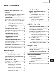
...Mode automatically 29 Changing the Wide Screen Mode manually 30 Changing the Wide Setup 30 Setting the Video Inputs 32 Operating Video Equipment with Your TV Remote Control 33 Programming the remote control 33 Operating optional equipment 35 Using Favorite Channels 36 Setting your ...48 Ratings in the U.S.A 48 Ratings in Canada 49 Adjusting Advanced AV Setting Options ...... 51 Using the Timer Turning Off the TV Automatically 54 Setting the Current Time 55 Controlling Power On/Off Automatically ..... 56 Additional Information Troubleshooting 58 Self-diagnosis function 58 ...
...Mode automatically 29 Changing the Wide Screen Mode manually 30 Changing the Wide Setup 30 Setting the Video Inputs 32 Operating Video Equipment with Your TV Remote Control 33 Programming the remote control 33 Operating optional equipment 35 Using Favorite Channels 36 Setting your ...48 Ratings in the U.S.A 48 Ratings in Canada 49 Adjusting Advanced AV Setting Options ...... 51 Using the Timer Turning Off the TV Automatically 54 Setting the Current Time 55 Controlling Power On/Off Automatically ..... 56 Additional Information Troubleshooting 58 Self-diagnosis function 58 ...
Operating Instructions
Page 6
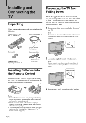
...8226; Your remote control can be used for the brackets also hold the rear cabinet in electric shock. Installing and Connecting the TV Installing and Connecting the TV Unpacking When you anticipate that attaches the rear cabinet. Avoid dropping it, getting it wet, or placing it to the diagram inside... screws attached at the same time as these screws secure the rear cabinet. Bracket (supplied) 3 Repeat steps 1 and 2 to use the TV with Your TV Remote Control" on the batteries to a wall or pillar. Note Be sure to attach the other brackets. Consult your dealer when attaching the ...
...8226; Your remote control can be used for the brackets also hold the rear cabinet in electric shock. Installing and Connecting the TV Installing and Connecting the TV Unpacking When you anticipate that attaches the rear cabinet. Avoid dropping it, getting it wet, or placing it to the diagram inside... screws attached at the same time as these screws secure the rear cabinet. Bracket (supplied) 3 Repeat steps 1 and 2 to use the TV with Your TV Remote Control" on the batteries to a wall or pillar. Note Be sure to attach the other brackets. Consult your dealer when attaching the ...
Operating Instructions
Page 7
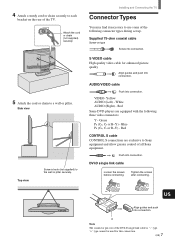
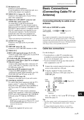
Supplied 75-ohm coaxial cable Screw-on the rear of all Sony equipment. Red CONTROL S cable CONTROL S connections are equipped with the following connector types during set up. DVI-D single link cable Loosen the screws before connecting. A ... the following three video connectors: Y - Attach the cord or chain (not supplied) securely. 5 Attach the cord or chain to Sony equipment and allow greater control of the TV. Installing and Connecting the TV Connector Types You may find it necessary to use some of the DVI-D single link cable is "-" type. VIDEO- Red...
Supplied 75-ohm coaxial cable Screw-on the rear of all Sony equipment. Red CONTROL S cable CONTROL S connections are equipped with the following connector types during set up. DVI-D single link cable Loosen the screws before connecting. A ... the following three video connectors: Y - Attach the cord or chain (not supplied) securely. 5 Attach the cord or chain to Sony equipment and allow greater control of the TV. Installing and Connecting the TV Connector Types You may find it necessary to use some of the DVI-D single link cable is "-" type. VIDEO- Red...
Operating Instructions
Page 8
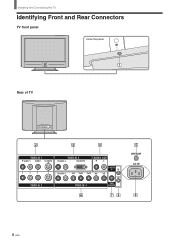
Installing and Connecting the TV Identifying Front and Rear Connectors TV front panel Under the panel Rear of TV VIDEO IN 1 R AUDIO L VIDEO S VIDEO VIDEO IN 3 R AUDIO L DVI-HDTV AUDIO OUT R L R AUDIO L Y/G PB/B PR/R HD CONTROL S IN VD OUT VIDEO IN 2 VIDEO IN 4 SUB WOOFER VHF/UHF AC IN 8 (US)
Installing and Connecting the TV Identifying Front and Rear Connectors TV front panel Under the panel Rear of TV VIDEO IN 1 R AUDIO L VIDEO S VIDEO VIDEO IN 3 R AUDIO L DVI-HDTV AUDIO OUT R L R AUDIO L Y/G PB/B PR/R HD CONTROL S IN VD OUT VIDEO IN 2 VIDEO IN 4 SUB WOOFER VHF/UHF AC IN 8 (US)
Operating Instructions
Page 9
...to the input jack of your sub woofer. 8 CONTROL S IN/OUT To control other Sony equipment with the TV's remote control,** connect the CONTROL S IN jack of the equipment to the CONTROL S OUT jack of the TV with the TV. * High-bandwidth Digital Content Protection 4 AUDIO OUT (page 13) Connects to the ..., and • You do not match the jack, use this hookup if: • You subscribe to a cable TV system that came with your equipment for another Sony equipment, connect the CONTROL S OUT jack of TV IN OUT Cable box Also, set -top boxes) that have DVI-HDTV. Installing and Connecting the...
...to the input jack of your sub woofer. 8 CONTROL S IN/OUT To control other Sony equipment with the TV's remote control,** connect the CONTROL S IN jack of the equipment to the CONTROL S OUT jack of the TV with the TV. * High-bandwidth Digital Content Protection 4 AUDIO OUT (page 13) Connects to the ..., and • You do not match the jack, use this hookup if: • You subscribe to a cable TV system that came with your equipment for another Sony equipment, connect the CONTROL S OUT jack of TV IN OUT Cable box Also, set -top boxes) that have DVI-HDTV. Installing and Connecting the...
Operating Instructions
Page 10
...VIDEO IN 2) separately. To watch the pictures input from the VIDEO input jack: Press V/v to select "Off," then press . 6 Press MENU to the TV's AUDIO and S VIDEO IN jacks. Rear of the S VIDEO cable. When connecting both VIDEO OUT and S VIDEO OUT You can set to receive S VIDEO... input signals. 1 Press TV/VIDEO repeatedly until the desired video input appears. 2 Press MENU. 3 Press V/v to select (Custom Setup), then press . 4 Press V/v to select "Auto YC," then...
...VIDEO IN 2) separately. To watch the pictures input from the VIDEO input jack: Press V/v to select "Off," then press . 6 Press MENU to the TV's AUDIO and S VIDEO IN jacks. Rear of the S VIDEO cable. When connecting both VIDEO OUT and S VIDEO OUT You can set to receive S VIDEO... input signals. 1 Press TV/VIDEO repeatedly until the desired video input appears. 2 Press MENU. 3 Press V/v to select (Custom Setup), then press . 4 Press V/v to select "Auto YC," then...
Operating Instructions
Page 11
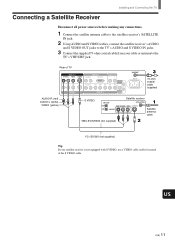
... to the satellite receiver's SATELLITE IN jack. 2 Using AUDIO and S VIDEO cables, connect the satellite receiver's AUDIO and S VIDEO OUT jacks to the TV's VHF/UHF jack. Rear of TV VIDEO IN 1 R AUDIO L VIDEO S VIDEO VIDEO IN 2 VIDEO IN 3 R AUDIO L DVI-HDTV AUDIO OUT R L R AUDIO L Y/G PB/B PR/R ...) S VIDEO Satellite receiver Satellite antenna cable VMC-810S/820S (not supplied) YC-15V/30V (not supplied) Tip If your cable or antenna to the TV's AUDIO and S VIDEO IN jacks. 3 Connect the supplied 75-ohm coaxial cable from your satellite receiver is not equipped with S VIDEO, use a...
... to the satellite receiver's SATELLITE IN jack. 2 Using AUDIO and S VIDEO cables, connect the satellite receiver's AUDIO and S VIDEO OUT jacks to the TV's VHF/UHF jack. Rear of TV VIDEO IN 1 R AUDIO L VIDEO S VIDEO VIDEO IN 2 VIDEO IN 3 R AUDIO L DVI-HDTV AUDIO OUT R L R AUDIO L Y/G PB/B PR/R ...) S VIDEO Satellite receiver Satellite antenna cable VMC-810S/820S (not supplied) YC-15V/30V (not supplied) Tip If your cable or antenna to the TV's AUDIO and S VIDEO IN jacks. 3 Connect the supplied 75-ohm coaxial cable from your satellite receiver is not equipped with S VIDEO, use a...
Operating Instructions
Page 12
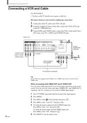
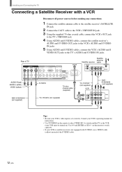
... Connect the CATV cable to the VCR's VHF/UHF IN jack. 3 Using the supplied 75-ohm coaxial cable, connect the VCR's OUT jack to the TV's VHF/UHF jack. 4 Using AUDIO and S VIDEO cables, connect the satellite receiver's AUDIO and S VIDEO OUT jacks to the VCR's AUDIO and .... 5 Using AUDIO and S VIDEO cables, connect the VCR's AUDIO and S VIDEO OUT jacks to the TV's AUDIO and S VIDEO IN jacks. Installing and Connecting the TV Connecting a Satellite Receiver with S VIDEO, use a VIDEO cable (yellow) instead of TV VIDEO IN 1 R AUDIO L VIDEO S VIDEO VIDEO IN 2 VIDEO IN 3 R AUDIO L DVI-HDTV AUDIO...
... Connect the CATV cable to the VCR's VHF/UHF IN jack. 3 Using the supplied 75-ohm coaxial cable, connect the VCR's OUT jack to the TV's VHF/UHF jack. 4 Using AUDIO and S VIDEO cables, connect the satellite receiver's AUDIO and S VIDEO OUT jacks to the VCR's AUDIO and .... 5 Using AUDIO and S VIDEO cables, connect the VCR's AUDIO and S VIDEO OUT jacks to the TV's AUDIO and S VIDEO IN jacks. Installing and Connecting the TV Connecting a Satellite Receiver with S VIDEO, use a VIDEO cable (yellow) instead of TV VIDEO IN 1 R AUDIO L VIDEO S VIDEO VIDEO IN 2 VIDEO IN 3 R AUDIO L DVI-HDTV AUDIO...
Operating Instructions
Page 13
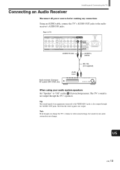
... that the video signal is not output through the AUDIO OUT jacks. Rear of your audio system does not change the TV's volume or other sound settings, the sound of TV VIDEO IN 1 R AUDIO L VIDEO S VIDEO VIDEO IN 2 COMPONENT VIDEO IN 1 AUDIO OUT R AUDIO L Y PB PR R L R AUDIO L Y/G... on the (Custom Setup) menu. Note Even though you change . Connecting an Audio Receiver Installing and Connecting the TV Disconnect all power sources before making any connections. The TV's sound is not output. Tip The sound signal of an equipment connected to the audio receiver's AUDIO IN jacks...
... that the video signal is not output through the AUDIO OUT jacks. Rear of your audio system does not change the TV's volume or other sound settings, the sound of TV VIDEO IN 1 R AUDIO L VIDEO S VIDEO VIDEO IN 2 COMPONENT VIDEO IN 1 AUDIO OUT R AUDIO L Y PB PR R L R AUDIO L Y/G... on the (Custom Setup) menu. Note Even though you change . Connecting an Audio Receiver Installing and Connecting the TV Disconnect all power sources before making any connections. The TV's sound is not output. Tip The sound signal of an equipment connected to the audio receiver's AUDIO IN jacks...

Operating Instructions
Page 14
If so, connect the cables to the matching colors. 2 Using an AUDIO cable, connect the DVD player's AUDIO OUT jacks to "Y/PB/ PR" in the (Initial Setup) menu (see page 32). Tip The Y, B-Y and R-Y jacks on your DVD player. For details, refer to the operating instructions supplied with your DVD ... with the three component video connectorsP: Y-Green, PB (CB, Cb or B-Y) -Blue and PR (CR, Cr or R-Y) -Red. Be sure to 16:9 on the TV. Rear of TV VIDEO IN 1 R AUDIO L VIDEO S VIDEO VIDEO IN 3 R AUDIO L DVI-HDTV AUDIO OUT R L R AUDIO L Y/G PB/B PR/R HD CONTROL S IN VD OUT VIDEO...
If so, connect the cables to the matching colors. 2 Using an AUDIO cable, connect the DVD player's AUDIO OUT jacks to "Y/PB/ PR" in the (Initial Setup) menu (see page 32). Tip The Y, B-Y and R-Y jacks on your DVD player. For details, refer to the operating instructions supplied with your DVD ... with the three component video connectorsP: Y-Green, PB (CB, Cb or B-Y) -Blue and PR (CR, Cr or R-Y) -Red. Be sure to 16:9 on the TV. Rear of TV VIDEO IN 1 R AUDIO L VIDEO S VIDEO VIDEO IN 3 R AUDIO L DVI-HDTV AUDIO OUT R L R AUDIO L Y/G PB/B PR/R HD CONTROL S IN VD OUT VIDEO...

Operating Instructions
Page 15
... page 14. Disconnect all power sources before making any connections. 1 Using an AUDIO cable, connect the DVD player's AUDIO OUT jacks to the TV's AUDIO IN jacks. 2 Using an S VIDEO cable, connect the DVD player's S VIDEO jack to the operating instructions supplied with your DVD... player has video component output connectors, for best picture quality, use a VIDEO cable (yellow) instead of the S VIDEO cable. Tips • To take advantage of TV AUDIO-R (red) AUDIO-L (white) VIDEO IN 1 R AUDIO L VIDEO S VIDEO VIDEO IN 2 VIDEO IN 3 R AUDIO L DVI-HDTV AUDIO OUT R L R AUDIO L Y/G PB/B ...
... page 14. Disconnect all power sources before making any connections. 1 Using an AUDIO cable, connect the DVD player's AUDIO OUT jacks to the TV's AUDIO IN jacks. 2 Using an S VIDEO cable, connect the DVD player's S VIDEO jack to the operating instructions supplied with your DVD... player has video component output connectors, for best picture quality, use a VIDEO cable (yellow) instead of the S VIDEO cable. Tips • To take advantage of TV AUDIO-R (red) AUDIO-L (white) VIDEO IN 1 R AUDIO L VIDEO S VIDEO VIDEO IN 2 VIDEO IN 3 R AUDIO L DVI-HDTV AUDIO OUT R L R AUDIO L Y/G PB/B ...
Operating Instructions
Page 16
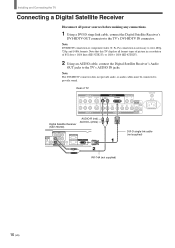
... a Digital Satellite Receiver Disconnect all format types of picture in a resolution of TV VIDEO IN 1 R AUDIO L VIDEO S VIDEO VIDEO IN 2 VIDEO IN 3 R AUDIO L DVI-HDTV AUDIO OUT R L R AUDIO L Y/G PB/B PR/R HD CONTROL S IN VD OUT VIDEO IN 4 SUB... sources before making any connections. 1 Using a DVI-D singe link cable, connect the Digital Satellite Receiver's DVI-HDTV OUT connector to the TV's AUDIO IN jacks. Rear of 852 dots × 1024 lines (KE-32TS2U), or 1024 × 1024 (KE-42TS2U). 2 Using an AUDIO cable, connect the Digital Satellite Receiver's Audio OUT jacks to the...
... a Digital Satellite Receiver Disconnect all format types of picture in a resolution of TV VIDEO IN 1 R AUDIO L VIDEO S VIDEO VIDEO IN 2 VIDEO IN 3 R AUDIO L DVI-HDTV AUDIO OUT R L R AUDIO L Y/G PB/B PR/R HD CONTROL S IN VD OUT VIDEO IN 4 SUB... sources before making any connections. 1 Using a DVI-D singe link cable, connect the Digital Satellite Receiver's DVI-HDTV OUT connector to the TV's AUDIO IN jacks. Rear of 852 dots × 1024 lines (KE-32TS2U), or 1024 × 1024 (KE-42TS2U). 2 Using an AUDIO cable, connect the Digital Satellite Receiver's Audio OUT jacks to the...
Operating Instructions
Page 17
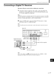
...PR) connection is necessary to provide sound. Connecting a Digital TV Receiver Installing and Connecting the TV Disconnect all format types of 852 dots × 1024 lines (KE-32TS2U), or 1024 × 1024 (KE-42TS2U). 2 Using an AUDIO cable, connect the Digital TV Set-top box's Audio OUT jacks to the Y/G, PB/B... and PR/R jacks on the Digital TV Set-top box you connect (see page 32). Rear of TV Digital TV Set-top box VIDEO IN...
...PR) connection is necessary to provide sound. Connecting a Digital TV Receiver Installing and Connecting the TV Disconnect all format types of 852 dots × 1024 lines (KE-32TS2U), or 1024 × 1024 (KE-42TS2U). 2 Using an AUDIO cable, connect the Digital TV Set-top box's Audio OUT jacks to the Y/G, PB/B... and PR/R jacks on the Digital TV Set-top box you connect (see page 32). Rear of TV Digital TV Set-top box VIDEO IN...
Operating Instructions
Page 18
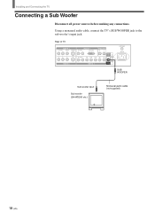
Installing and Connecting the TV Connecting a Sub Woofer Disconnect all power sources before making any connections. Rear of TV VIDEO IN 1 R AUDIO L VIDEO S VIDEO VIDEO IN 2 VIDEO IN 3 R AUDIO L DVI-HDTV AUDIO OUT R L R AUDIO L Y/G PB/B PR/R HD CONTROL S IN VD OUT VIDEO IN 4 SUB WOOFER VHF/UHF AC IN SUB WOOFER Sub woofer input Sub woofer (SA-WD200 etc.) Monaural audio cable (not supplied) 18 (US) Using a monaural audio cable, connect the TV's SUB WOOFER jack to the sub woofer's input jack.
Installing and Connecting the TV Connecting a Sub Woofer Disconnect all power sources before making any connections. Rear of TV VIDEO IN 1 R AUDIO L VIDEO S VIDEO VIDEO IN 2 VIDEO IN 3 R AUDIO L DVI-HDTV AUDIO OUT R L R AUDIO L Y/G PB/B PR/R HD CONTROL S IN VD OUT VIDEO IN 4 SUB WOOFER VHF/UHF AC IN SUB WOOFER Sub woofer input Sub woofer (SA-WD200 etc.) Monaural audio cable (not supplied) 18 (US) Using a monaural audio cable, connect the TV's SUB WOOFER jack to the sub woofer's input jack.

Operating Instructions
Page 19
.... 2 Using an AUDIO cable, connect the RGB equipment's AUDIO OUT jacks to the Y/G, PB/B, PR/R, HD, and VD jacks on the TV. Be sure to use the same row of TV VIDEO IN 1 R AUDIO L VIDEO S VIDEO VIDEO IN 2 VIDEO IN 3 R AUDIO L DVI-HDTV AUDIO OUT R L R AUDIO L Y/G PB/B PR/R HD CONTROL S... IN VD OUT VIDEO IN 4 SUB WOOFER RGB equipment VHF/UHF AC IN Note Set "Video 4 Mode" to "RGB" in the (Initial Setup) menu (see page 32).
.... 2 Using an AUDIO cable, connect the RGB equipment's AUDIO OUT jacks to the Y/G, PB/B, PR/R, HD, and VD jacks on the TV. Be sure to use the same row of TV VIDEO IN 1 R AUDIO L VIDEO S VIDEO VIDEO IN 2 VIDEO IN 3 R AUDIO L DVI-HDTV AUDIO OUT R L R AUDIO L Y/G PB/B PR/R HD CONTROL S... IN VD OUT VIDEO IN 4 SUB WOOFER RGB equipment VHF/UHF AC IN Note Set "Video 4 Mode" to "RGB" in the (Initial Setup) menu (see page 32).
