Operating Instructions
Page 8
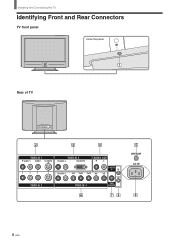
Installing and Connecting the TV Identifying Front and Rear Connectors TV front panel Under the panel Rear of TV VIDEO IN 1 R AUDIO L VIDEO S VIDEO VIDEO IN 3 R AUDIO L DVI-HDTV AUDIO OUT R L R AUDIO L Y/G PB/B PR/R HD CONTROL S IN VD OUT VIDEO IN 2 VIDEO IN 4 SUB WOOFER VHF/UHF AC IN 8 (US)
Installing and Connecting the TV Identifying Front and Rear Connectors TV front panel Under the panel Rear of TV VIDEO IN 1 R AUDIO L VIDEO S VIDEO VIDEO IN 3 R AUDIO L DVI-HDTV AUDIO OUT R L R AUDIO L Y/G PB/B PR/R HD CONTROL S IN VD OUT VIDEO IN 2 VIDEO IN 4 SUB WOOFER VHF/UHF AC IN 8 (US)
Operating Instructions
Page 9
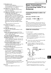
...21). Y/G, PB/B, PR/R, HD, VD input jacks: Connecting a DVD player (page 14) or a Digital TV Receiver (page 17) Connect with personal computers. To control the TV with a remote control for another Sony equipment, connect the CONTROL S OUT jack of the equipment to the CONTROL S IN jack on page 33)....your sub woofer. 8 CONTROL S IN/OUT To control other Sony equipment with the TV's remote control,** connect the CONTROL S IN jack of the equipment to the CONTROL S OUT jack of your VCR or other video equipment. 3 VIDEO IN 3 (DVI-HDTV connector and AUDIO (R/L) jacks) (page 16) Accommodates a ...
...21). Y/G, PB/B, PR/R, HD, VD input jacks: Connecting a DVD player (page 14) or a Digital TV Receiver (page 17) Connect with personal computers. To control the TV with a remote control for another Sony equipment, connect the CONTROL S OUT jack of the equipment to the CONTROL S IN jack on page 33)....your sub woofer. 8 CONTROL S IN/OUT To control other Sony equipment with the TV's remote control,** connect the CONTROL S IN jack of the equipment to the CONTROL S OUT jack of your VCR or other video equipment. 3 VIDEO IN 3 (DVI-HDTV connector and AUDIO (R/L) jacks) (page 16) Accommodates a ...
Operating Instructions
Page 10
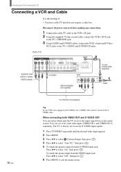
... not equipped with S VIDEO, use a VIDEO cable (yellow) instead of TV AUDIO-R (red) AUDIO-L (white) VIDEO (yellow) VIDEO IN 1 R AUDIO L VIDEO S VIDEO VIDEO IN 3 R AUDIO L DVI-HDTV AUDIO OUT R L R AUDIO L Y/G PB/B PR/R HD CONTROL S IN VD OUT VIDEO IN 2 VIDEO IN 4 SUB WOOFER S VIDEO VCR VHF... does not require a cable box. When connecting both VIDEO OUT and S VIDEO OUT You can set to receive S VIDEO input signals. 1 Press TV/VIDEO repeatedly until the desired video input appears. 2 Press MENU. 3 Press V/v to select (Custom Setup), then press . 4 Press V/v to select "Auto ...
... not equipped with S VIDEO, use a VIDEO cable (yellow) instead of TV AUDIO-R (red) AUDIO-L (white) VIDEO (yellow) VIDEO IN 1 R AUDIO L VIDEO S VIDEO VIDEO IN 3 R AUDIO L DVI-HDTV AUDIO OUT R L R AUDIO L Y/G PB/B PR/R HD CONTROL S IN VD OUT VIDEO IN 2 VIDEO IN 4 SUB WOOFER S VIDEO VCR VHF... does not require a cable box. When connecting both VIDEO OUT and S VIDEO OUT You can set to receive S VIDEO input signals. 1 Press TV/VIDEO repeatedly until the desired video input appears. 2 Press MENU. 3 Press V/v to select (Custom Setup), then press . 4 Press V/v to select "Auto ...
Operating Instructions
Page 11
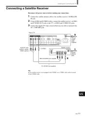
...jack. 2 Using AUDIO and S VIDEO cables, connect the satellite receiver's AUDIO and S VIDEO OUT jacks to the TV's VHF/UHF jack. Rear of TV VIDEO IN 1 R AUDIO L VIDEO S VIDEO VIDEO IN 2 VIDEO IN 3 R AUDIO L DVI-HDTV AUDIO OUT R L R AUDIO L Y/G PB/B PR/R HD CONTROL S IN VD OUT VIDEO IN 4 SUB ...) S VIDEO Satellite receiver Satellite antenna cable VMC-810S/820S (not supplied) YC-15V/30V (not supplied) Tip If your cable or antenna to the TV's AUDIO and S VIDEO IN jacks. 3 Connect the supplied 75-ohm coaxial cable from your satellite receiver is not equipped with S VIDEO, use a ...
...jack. 2 Using AUDIO and S VIDEO cables, connect the satellite receiver's AUDIO and S VIDEO OUT jacks to the TV's VHF/UHF jack. Rear of TV VIDEO IN 1 R AUDIO L VIDEO S VIDEO VIDEO IN 2 VIDEO IN 3 R AUDIO L DVI-HDTV AUDIO OUT R L R AUDIO L Y/G PB/B PR/R HD CONTROL S IN VD OUT VIDEO IN 4 SUB ...) S VIDEO Satellite receiver Satellite antenna cable VMC-810S/820S (not supplied) YC-15V/30V (not supplied) Tip If your cable or antenna to the TV's AUDIO and S VIDEO IN jacks. 3 Connect the supplied 75-ohm coaxial cable from your satellite receiver is not equipped with S VIDEO, use a ...
Operating Instructions
Page 12
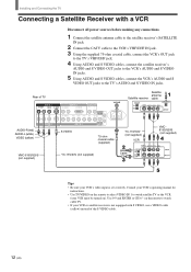
... the VCR (your VCR must be turned on). Rear of TV VIDEO IN 1 R AUDIO L VIDEO S VIDEO VIDEO IN 2 VIDEO IN 3 R AUDIO L DVI-HDTV AUDIO OUT R L R AUDIO L Y/G PB/B PR/R HD CONTROL S IN VD OUT VIDEO IN 4 SUB WOOFER VHF/UHF AC IN AUDIO-R (red) AUDIO-L (white) VIDEO (yellow) S VIDEO .... 2 Connect the CATV cable to the VCR's VHF/UHF IN jack. 3 Using the supplied 75-ohm coaxial cable, connect the VCR's OUT jack to the TV's VHF/UHF jack. 4 Using AUDIO and S VIDEO cables, connect the satellite receiver's AUDIO and S VIDEO OUT jacks to the VCR's AUDIO and S VIDEO IN jacks...
... the VCR (your VCR must be turned on). Rear of TV VIDEO IN 1 R AUDIO L VIDEO S VIDEO VIDEO IN 2 VIDEO IN 3 R AUDIO L DVI-HDTV AUDIO OUT R L R AUDIO L Y/G PB/B PR/R HD CONTROL S IN VD OUT VIDEO IN 4 SUB WOOFER VHF/UHF AC IN AUDIO-R (red) AUDIO-L (white) VIDEO (yellow) S VIDEO .... 2 Connect the CATV cable to the VCR's VHF/UHF IN jack. 3 Using the supplied 75-ohm coaxial cable, connect the VCR's OUT jack to the TV's VHF/UHF jack. 4 Using AUDIO and S VIDEO cables, connect the satellite receiver's AUDIO and S VIDEO OUT jacks to the VCR's AUDIO and S VIDEO IN jacks...

Operating Instructions
Page 14
... making any connections. 1 Using three separate component video cables, connect the DVD player's Y, B-Y and R-Y jacks to use the same row of TV VIDEO IN 1 R AUDIO L VIDEO S VIDEO VIDEO IN 3 R AUDIO L DVI-HDTV AUDIO OUT R L R AUDIO L Y/G PB/B PR/R HD CONTROL S IN VD OUT VIDEO IN 2 VIDEO IN 4 SUB WOOFER AUDIO-R ... (US) Note Set "Video 4 Mode" to "Y/PB/ PR" in the (Initial Setup) menu (see page 32). Use the VIDEO IN 4 connections. If so, connect the cables to the matching colors. 2 Using an AUDIO cable, connect the DVD player's AUDIO OUT jacks to use if: • Your DVD ...
... making any connections. 1 Using three separate component video cables, connect the DVD player's Y, B-Y and R-Y jacks to use the same row of TV VIDEO IN 1 R AUDIO L VIDEO S VIDEO VIDEO IN 3 R AUDIO L DVI-HDTV AUDIO OUT R L R AUDIO L Y/G PB/B PR/R HD CONTROL S IN VD OUT VIDEO IN 2 VIDEO IN 4 SUB WOOFER AUDIO-R ... (US) Note Set "Video 4 Mode" to "Y/PB/ PR" in the (Initial Setup) menu (see page 32). Use the VIDEO IN 4 connections. If so, connect the cables to the matching colors. 2 Using an AUDIO cable, connect the DVD player's AUDIO OUT jacks to use if: • Your DVD ...

Operating Instructions
Page 15
...your DVD player has video component output connectors, for best picture quality, use a VIDEO cable (yellow) instead of TV AUDIO-R (red) AUDIO-L (white) VIDEO IN 1 R AUDIO L VIDEO S VIDEO VIDEO IN 2 VIDEO IN 3 R AUDIO L DVI-HDTV AUDIO OUT R L R AUDIO L Y/G PB/B PR/R HD CONTROL S IN VD OUT VIDEO IN 4 ...SUB WOOFER S VIDEO VHF/UHF AC IN RK-74A (not supplied) YC-15V/30V (not supplied) DVD player Note To watch cable TV. • If your DVD player. Rear of...
...your DVD player has video component output connectors, for best picture quality, use a VIDEO cable (yellow) instead of TV AUDIO-R (red) AUDIO-L (white) VIDEO IN 1 R AUDIO L VIDEO S VIDEO VIDEO IN 2 VIDEO IN 3 R AUDIO L DVI-HDTV AUDIO OUT R L R AUDIO L Y/G PB/B PR/R HD CONTROL S IN VD OUT VIDEO IN 4 ...SUB WOOFER S VIDEO VHF/UHF AC IN RK-74A (not supplied) YC-15V/30V (not supplied) DVD player Note To watch cable TV. • If your DVD player. Rear of...
Operating Instructions
Page 16
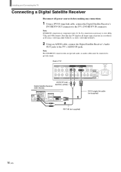
...) connection is necessary to provide sound. Note The DVI-HDTV connector does not provide audio, so audio cables must be connected to view 480p, 720p, and 1080i formats. Rear of 852 dots × 1024 lines (KE-32TS2U), or 1024 × 1024 (KE-42TS2U). 2 Using an AUDIO cable, connect the Digital ...Satellite Receiver's Audio OUT jacks to the TV's DVI-HDTV IN connector. VIDEO R1 R2 AUDIO OUT VIDEO OUT (1080i/720p/480p) Y PB...
...) connection is necessary to provide sound. Note The DVI-HDTV connector does not provide audio, so audio cables must be connected to view 480p, 720p, and 1080i formats. Rear of 852 dots × 1024 lines (KE-32TS2U), or 1024 × 1024 (KE-42TS2U). 2 Using an AUDIO cable, connect the Digital ...Satellite Receiver's Audio OUT jacks to the TV's DVI-HDTV IN connector. VIDEO R1 R2 AUDIO OUT VIDEO OUT (1080i/720p/480p) Y PB...
Operating Instructions
Page 17
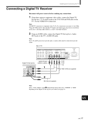
.../B and PR/R jacks on the Digital TV Set-top box you connect (see page 32). Rear of 852 dots × 1024 lines (KE-32TS2U), or 1024 × 1024 (KE-42TS2U). 2 Using an AUDIO cable, connect the Digital TV Set-top box's Audio OUT jacks to the TV's AUDIO IN jacks. Note DVI-HDTV connection or component video (Y, PB...
.../B and PR/R jacks on the Digital TV Set-top box you connect (see page 32). Rear of 852 dots × 1024 lines (KE-32TS2U), or 1024 × 1024 (KE-42TS2U). 2 Using an AUDIO cable, connect the Digital TV Set-top box's Audio OUT jacks to the TV's AUDIO IN jacks. Note DVI-HDTV connection or component video (Y, PB...
Operating Instructions
Page 18
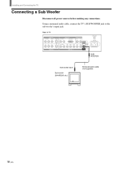
Rear of TV VIDEO IN 1 R AUDIO L VIDEO S VIDEO VIDEO IN 2 VIDEO IN 3 R AUDIO L DVI-HDTV AUDIO OUT R L R AUDIO L Y/G PB/B PR/R HD CONTROL S IN VD OUT VIDEO IN 4 SUB WOOFER VHF/UHF AC IN SUB WOOFER Sub woofer input Sub woofer (SA-WD200 etc.) Monaural audio cable (not supplied) 18 (US) Installing and Connecting the TV Connecting a Sub Woofer Disconnect all power sources before making any connections. Using a monaural audio cable, connect the TV's SUB WOOFER jack to the sub woofer's input jack.
Rear of TV VIDEO IN 1 R AUDIO L VIDEO S VIDEO VIDEO IN 2 VIDEO IN 3 R AUDIO L DVI-HDTV AUDIO OUT R L R AUDIO L Y/G PB/B PR/R HD CONTROL S IN VD OUT VIDEO IN 4 SUB WOOFER VHF/UHF AC IN SUB WOOFER Sub woofer input Sub woofer (SA-WD200 etc.) Monaural audio cable (not supplied) 18 (US) Installing and Connecting the TV Connecting a Sub Woofer Disconnect all power sources before making any connections. Using a monaural audio cable, connect the TV's SUB WOOFER jack to the sub woofer's input jack.

Operating Instructions
Page 19
...the Y/G, PB/B, PR/R, HD, and VD jacks on the TV. US (US) 19 Connecting an RGB Equipment Installing and Connecting the TV Disconnect all power sources before making any connections. 1 Using an... RGB cable, connect the RGB equipment's video/synchronized signal output terminal to the TV's AUDIO IN jacks... for the video connection. Be sure to use the same row of TV VIDEO IN 1 R AUDIO L VIDEO S VIDEO VIDEO IN 2 VIDEO IN 3 R AUDIO L DVI-HDTV AUDIO OUT R L R AUDIO L Y/G PB/B PR/R HD CONTROL...
...the Y/G, PB/B, PR/R, HD, and VD jacks on the TV. US (US) 19 Connecting an RGB Equipment Installing and Connecting the TV Disconnect all power sources before making any connections. 1 Using an... RGB cable, connect the RGB equipment's video/synchronized signal output terminal to the TV's AUDIO IN jacks... for the video connection. Be sure to use the same row of TV VIDEO IN 1 R AUDIO L VIDEO S VIDEO VIDEO IN 2 VIDEO IN 3 R AUDIO L DVI-HDTV AUDIO OUT R L R AUDIO L Y/G PB/B PR/R HD CONTROL...
Operating Instructions
Page 61
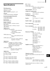
... TV standard Channel coverage: VHF: 2-13/UHF: 14-69/CATV: 1-125 Antenna: 75 ohm external terminal for VHF/UHF Screen size (measured diagonally): 32 inches (KE-32TS2U) 42 inches (KE-42TS2U) Panel System: Plasma Display panel Display resolution: 852 dots (horizontal) × 1024 lines (vertical) (KE-32TS2U)...), Impedance: 47 kilohms VIDEO IN 3: DVI-HDTV : 1 terminal, 3.3V T.M.D.S., 50 ohms DVI-HDTV input terminal is compliant with the EIA-861 standard and is not intended for use (Max.): KE-32TS2U:300W KE-42TS2U:415W In standby: KE-32TS2U:1.7W KE-42TS2U:2.9W Dimensions (W/H/D): 856 × 627 ...
... TV standard Channel coverage: VHF: 2-13/UHF: 14-69/CATV: 1-125 Antenna: 75 ohm external terminal for VHF/UHF Screen size (measured diagonally): 32 inches (KE-32TS2U) 42 inches (KE-42TS2U) Panel System: Plasma Display panel Display resolution: 852 dots (horizontal) × 1024 lines (vertical) (KE-32TS2U)...), Impedance: 47 kilohms VIDEO IN 3: DVI-HDTV : 1 terminal, 3.3V T.M.D.S., 50 ohms DVI-HDTV input terminal is compliant with the EIA-861 standard and is not intended for use (Max.): KE-32TS2U:300W KE-42TS2U:415W In standby: KE-32TS2U:1.7W KE-42TS2U:2.9W Dimensions (W/H/D): 856 × 627 ...
