
Operating Instructions
Page 2
... of Parts 6 Front Panel ...6 Rear Panel ...16 Supplied Remote Commander 21 Displaying Various Data 23 Chapter 2 Playback and Recording Notes on Power Supply and Video Cassettes 28 Preparing the Power Supply 29 Turning the Power on 29 Inserting/Ejecting Cassettes 29 Notes on Playback...Auto Repeat (CUSTOM REPEAT 42 EDGE CROP MARKER 44 MARKER BURN 45 Using the Unit as a Videocassette Recorder 46 Connections for Recording 46 Settings for Recording 48 Recording Procedures 50 Recording Functions 50 Chapter 3 Utilizing the Time Code Setting the Time Code and User Bits 52 Using the ...
... of Parts 6 Front Panel ...6 Rear Panel ...16 Supplied Remote Commander 21 Displaying Various Data 23 Chapter 2 Playback and Recording Notes on Power Supply and Video Cassettes 28 Preparing the Power Supply 29 Turning the Power on 29 Inserting/Ejecting Cassettes 29 Notes on Playback...Auto Repeat (CUSTOM REPEAT 42 EDGE CROP MARKER 44 MARKER BURN 45 Using the Unit as a Videocassette Recorder 46 Connections for Recording 46 Settings for Recording 48 Recording Procedures 50 Recording Functions 50 Chapter 3 Utilizing the Time Code Setting the Time Code and User Bits 52 Using the ...

Operating Instructions
Page 3
... 63 Editing (Connecting a Computer 65 Connecting the Unit to a Computer 65 Preparations...66 Chapter 5 Adjusting and Setting Through Menus Operating Menus 68 Menu Structure 69 Menu Contents 70 Chapter 6 Maintenance Troubleshooting 83 Warning Indicators and Messages 90 Notes on Use 92 Notes on the Videocassette Recorder 92 Cleaning of the Video Heads 92 Notes...
... 63 Editing (Connecting a Computer 65 Connecting the Unit to a Computer 65 Preparations...66 Chapter 5 Adjusting and Setting Through Menus Operating Menus 68 Menu Structure 69 Menu Contents 70 Chapter 6 Maintenance Troubleshooting 83 Warning Indicators and Messages 90 Notes on Use 92 Notes on the Videocassette Recorder 92 Cleaning of the Video Heads 92 Notes...
Operating Instructions
Page 4
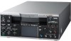
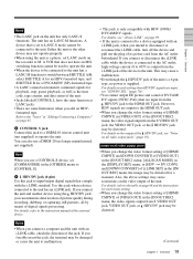
... signals and a luminance signal (component video). Definition Digital Video) recording and playback. The unit is equipped with i.LINK and HDMI (output) digital interfaces, and can be input only via an i.LINK digital interface.) Here for professional use. High definition down convert function When...1080/25p videos. The compression system of the HDV format is not compatible with both DVCAM format recording/playback and DV format in SP mode recording/playback. The unit provides both interlaced and progressive HDV recording/playback The unit can be digitally connected with ...
... signals and a luminance signal (component video). Definition Digital Video) recording and playback. The unit is equipped with i.LINK and HDMI (output) digital interfaces, and can be input only via an i.LINK digital interface.) Here for professional use. High definition down convert function When...1080/25p videos. The compression system of the HDV format is not compatible with both DVCAM format recording/playback and DV format in SP mode recording/playback. The unit provides both interlaced and progressive HDV recording/playback The unit can be digitally connected with ...

Operating Instructions
Page 5
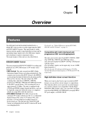
...VIDEO OUT jack. • Digital hours meter: A digital hours meter counts four types of Japan, Ltd. JOG AUDIO function If you can use the optional DSRM-10 remote control unit (not supplied), audio can be output when the tape is a trademark of Sony Corporation and Victor Company of time data- is recorded...can be set easily. Easy maintenance functions • Self-diagnostics/alarm functions: The system automatically detects an invalid operation, bad connection, or a malfunction, and displays a description, a cause, and a recovery method on the spot. A variety of buttons ...
...VIDEO OUT jack. • Digital hours meter: A digital hours meter counts four types of Japan, Ltd. JOG AUDIO function If you can use the optional DSRM-10 remote control unit (not supplied), audio can be output when the tape is a trademark of Sony Corporation and Victor Company of time data- is recorded...can be set easily. Easy maintenance functions • Self-diagnostics/alarm functions: The system automatically detects an invalid operation, bad connection, or a malfunction, and displays a description, a cause, and a recovery method on the spot. A variety of buttons ...

Operating Instructions
Page 7
.../phones) LEVEL control knob Controls the volume of the speaker qa on the bottom plate of the unit as well as that of the headphones connected to the i (phones) jack 8. • The volume of the speaker and headphones are output via the AUDIO OUT jack and HDMI OUT jack on each.... • By changing the setting of the following items on page 11. • When the audio mode is output. OFF: Auto Repeat or timer recording is connected to the unit. Chapter 1 Overview Notes • When the ON/STANDBY lamp is supplied to the unit, the tape rewinds to its beginning automatically and...
.../phones) LEVEL control knob Controls the volume of the speaker qa on the bottom plate of the unit as well as that of the headphones connected to the i (phones) jack 8. • The volume of the speaker and headphones are output via the AUDIO OUT jack and HDMI OUT jack on each.... • By changing the setting of the following items on page 11. • When the audio mode is output. OFF: Auto Repeat or timer recording is connected to the unit. Chapter 1 Overview Notes • When the ON/STANDBY lamp is supplied to the unit, the tape rewinds to its beginning automatically and...

Operating Instructions
Page 8
...with [ASSIGN [A1]] of [ASSIGN BTN] in progress, the output signal via the HDV/DV jack may be recorded discontinuously. • If you have set. HDV/DV: Inputs a signal from the S VIDEO IN jack. Also, the time code may detect signals, such as a copyright information signal, incorrectly. • When... (A1) button. For details on the headphones output, see "Recording Functions" on page 50. ALL: Superimposes text data to S VIDEO OUT jack and VIDEO OUT jack. If you search for the text data to be monitored are connected, no sound is ejected. Indexing is useful when you press this...
...with [ASSIGN [A1]] of [ASSIGN BTN] in progress, the output signal via the HDV/DV jack may be recorded discontinuously. • If you have set. HDV/DV: Inputs a signal from the S VIDEO IN jack. Also, the time code may detect signals, such as a copyright information signal, incorrectly. • When... (A1) button. For details on the headphones output, see "Recording Functions" on page 50. ALL: Superimposes text data to S VIDEO OUT jack and VIDEO OUT jack. If you search for the text data to be monitored are connected, no sound is ejected. Indexing is useful when you press this...

Operating Instructions
Page 16
...details on page 89. 16 Chapter 1 Overview During audio dubbing, sounds are recorded onto channels 1 and 2. Note If this switch, see "Notes on all video output jacks" on an external monitor connected to the standard VIDEO jack. When the DISPLAY OUTPUT switch on the front panel is superimposed on page...For details on the output of the devices you can select audio signals to be output with less signal quality deterioration than if connected to the S VIDEO OUT jack (page 23). c AUDIO jacks Use these jacks to input and output analog audio signals. Location and Function of ...
...details on page 89. 16 Chapter 1 Overview During audio dubbing, sounds are recorded onto channels 1 and 2. Note If this switch, see "Notes on all video output jacks" on an external monitor connected to the standard VIDEO jack. When the DISPLAY OUTPUT switch on the front panel is superimposed on page...For details on the output of the devices you can select audio signals to be output with less signal quality deterioration than if connected to the S VIDEO OUT jack (page 23). c AUDIO jacks Use these jacks to input and output analog audio signals. Location and Function of ...

Operating Instructions
Page 17
... then output. • When you can output high-quality video with less signal quality deterioration than the COMPONENT OUT jacks. To connect a device equipped component video input connectors, use the COMPONENT OUT jacks on the unit. To connect a device equipped with copyright protection to ALL, text data such..., menu, and alarm messages are output in [480i LEVEL] of the text image data (outer frame: underscan portion) on a monitor connected using [HDMI/ CMPNT] of [VIDEO OUT] in the [IN/OUT REC] menu. When the DISPLAY OUTPUT switch is as with 0.6 Vp-p 3-level sync f HDMI OUT...
... then output. • When you can output high-quality video with less signal quality deterioration than the COMPONENT OUT jacks. To connect a device equipped component video input connectors, use the COMPONENT OUT jacks on the unit. To connect a device equipped with copyright protection to ALL, text data such..., menu, and alarm messages are output in [480i LEVEL] of the text image data (outer frame: underscan portion) on a monitor connected using [HDMI/ CMPNT] of [VIDEO OUT] in the [IN/OUT REC] menu. When the DISPLAY OUTPUT switch is as with 0.6 Vp-p 3-level sync f HDMI OUT...

Operating Instructions
Page 18
... Control bus system): Bidirectional interface used to connect the monitor and the unit. Text data and menus cannot be output. To output the sound of CH3 and CH4 when playing back a tape recorded in the [IN/OUT REC] menu, the video signal output from the S VIDEO OUT jack, VIDEO OUT jack, or HDV/DV jack...
... Control bus system): Bidirectional interface used to connect the monitor and the unit. Text data and menus cannot be output. To output the sound of CH3 and CH4 when playing back a tape recorded in the [IN/OUT REC] menu, the video signal output from the S VIDEO OUT jack, VIDEO OUT jack, or HDV/DV jack...
Operating Instructions
Page 19
... • If the unit is connected to the instruction manual of DVCAM/ DV signals (NTSC, PAL) that does not have the same function as a player, set to the unit. If you change the video format setting of [HDMI/ CMPNT] and [DOWN CONVERT] of [VIDEO OUT] in the [IN/OUT REC...the unit has an i.LINK jack. Chapter 1 Overview Notes • The LANC jack on the video output of picture quality during recording, dubbing, or capturing still pictures, all video output jacks" (page 19). Notes • When you connect a computer and the unit with an i.LINK jack, when you change the...
... • If the unit is connected to the instruction manual of DVCAM/ DV signals (NTSC, PAL) that does not have the same function as a player, set to the unit. If you change the video format setting of [HDMI/ CMPNT] and [DOWN CONVERT] of [VIDEO OUT] in the [IN/OUT REC...the unit has an i.LINK jack. Chapter 1 Overview Notes • The LANC jack on the video output of picture quality during recording, dubbing, or capturing still pictures, all video output jacks" (page 19). Notes • When you connect a computer and the unit with an i.LINK jack, when you change the...

Operating Instructions
Page 20
...monitor you do not intend to each analog output jack, the distortion of the video signals occurs at a speed other recording device via the analog jacks of the unit. • Depending on the TV monitor being connected, the screen may appear at the bottom of the screen. Be aware of ...not be distorted when DVCAM/DV signals which are input from the VIDEO IN jacks or S VIDEO IN jacks, are output to these phenomena when you connect other recording device to the VIDEO OUT jacks. Be aware of these phenomena when you connect other than the menu settings. Even if the unit is not a...
...monitor you do not intend to each analog output jack, the distortion of the video signals occurs at a speed other recording device via the analog jacks of the unit. • Depending on the TV monitor being connected, the screen may appear at the bottom of the screen. Be aware of ...not be distorted when DVCAM/DV signals which are input from the VIDEO IN jacks or S VIDEO IN jacks, are output to these phenomena when you connect other recording device to the VIDEO OUT jacks. Be aware of these phenomena when you connect other than the menu settings. Even if the unit is not a...

Operating Instructions
Page 23
... [HDV720p], [DVCAM], or [DV SP] are output in English. f x.v.Color indicator Displays an x.v.Color indicator while pictures recorded in LCD monitor, and also on an external monitor connected to [ON] in the underscan mode. h Tape transport mode indicator Displays the tape transport mode. (Continued) 23 Chapter 1... the S VIDEO OUT jack or VIDEO OUT jack. d HVR-DR60/HVR-MRC1 connection indicator [HDD] is displayed while an HVR-DR60 is turned on page 80. You can confirm important information for normal recording or playback, such as time code or remaining tape time, on a monitor...
... [HDV720p], [DVCAM], or [DV SP] are output in English. f x.v.Color indicator Displays an x.v.Color indicator while pictures recorded in LCD monitor, and also on an external monitor connected to [ON] in the underscan mode. h Tape transport mode indicator Displays the tape transport mode. (Continued) 23 Chapter 1... the S VIDEO OUT jack or VIDEO OUT jack. d HVR-DR60/HVR-MRC1 connection indicator [HDD] is displayed while an HVR-DR60 is turned on page 80. You can confirm important information for normal recording or playback, such as time code or remaining tape time, on a monitor...

Operating Instructions
Page 25
...-DR60 or an HVR-MRC1 is set to [AUDIO]. This screen displays the audio level meter and the setting values of the tape where the recording format has been changed .) (Continued) 25 Chapter 1 Overview The audio level meter is displayed in the [AUDIO SET] menu. The displayed value of ..., press the STATUS CHECK button again. Audio level meter and audio setting screen The audio setting screen is displayed when the STATUS CHECK screen is connected using the HDV/DV jack, the device information can adjust the settings of the "hour" is not displayed. (i.e., If the actual count value is ...
...-DR60 or an HVR-MRC1 is set to [AUDIO]. This screen displays the audio level meter and the setting values of the tape where the recording format has been changed .) (Continued) 25 Chapter 1 Overview The audio level meter is displayed in the [AUDIO SET] menu. The displayed value of ..., press the STATUS CHECK button again. Audio level meter and audio setting screen The audio setting screen is displayed when the STATUS CHECK screen is connected using the HDV/DV jack, the device information can adjust the settings of the "hour" is not displayed. (i.e., If the actual count value is ...

Operating Instructions
Page 29
Reel Inserting/Ejecting Cassettes To insert a cassette After checking the tape for slack, hold the back edge of the cassette compartment.) Preparing the Power Supply Connect the power cord (supplied) to the wall outlet. Then press the ON/STANDBY button on [CLOCK SET], see page 81. In such a case, if ... the tape for slack Using a paper clip or a similar object, turn on the tape being loaded. 29 Chapter 2 Playback and Recording Then, connect the power plug to the AC IN connector. The internal sensor of the unit to recognize the cassette and find the proper location on the...
Reel Inserting/Ejecting Cassettes To insert a cassette After checking the tape for slack, hold the back edge of the cassette compartment.) Preparing the Power Supply Connect the power cord (supplied) to the wall outlet. Then press the ON/STANDBY button on [CLOCK SET], see page 81. In such a case, if ... the tape for slack Using a paper clip or a similar object, turn on the tape being loaded. 29 Chapter 2 Playback and Recording Then, connect the power plug to the AC IN connector. The internal sensor of the unit to recognize the cassette and find the proper location on the...

Operating Instructions
Page 30
... the point where the recording format changes on another device connected to -remember name for the xvYCC standard. • The xvYCC standard is an international standard for if recording or playback is not successful due to the copyright laws. Unauthorized recording of the unit, video tape, etc. The ... a wider range of the SD format. Chapter 2 Playback and Recording Notes on Power Supply and Video Cassettes To eject the cassette With the unit powered on the unit that Sony is proposing as a easy-to your unit. On recording You cannot record software on , press the EJECT button.
... the point where the recording format changes on another device connected to -remember name for the xvYCC standard. • The xvYCC standard is an international standard for if recording or playback is not successful due to the copyright laws. Unauthorized recording of the unit, video tape, etc. The ... a wider range of the SD format. Chapter 2 Playback and Recording Notes on Power Supply and Video Cassettes To eject the cassette With the unit powered on the unit that Sony is proposing as a easy-to your unit. On recording You cannot record software on , press the EJECT button.

Operating Instructions
Page 32
... signals cannot be displayed depending on the unit. 32 Chapter 2 Playback and Recording This will not appear while recording with the unit. DVCAM/DV - - Be aware of these phenomena when you connect other recording device to the jitter. a 3) a 3) - HDMI OUT COMPONENT OUT VIDEO/ S VIDEO a 1) a 1) a (480i) 2) a 1) a 1) a (480i) 2) a 1) a 1) a (480i) 2) a 1) a 1) a (576i) 2) a 1) a 1) a (576i) 2) - - - - For details, see the settings for down...
... signals cannot be displayed depending on the unit. 32 Chapter 2 Playback and Recording This will not appear while recording with the unit. DVCAM/DV - - Be aware of these phenomena when you connect other recording device to the jitter. a 3) a 3) - HDMI OUT COMPONENT OUT VIDEO/ S VIDEO a 1) a 1) a (480i) 2) a 1) a 1) a (480i) 2) a 1) a 1) a (480i) 2) a 1) a 1) a (576i) 2) a 1) a 1) a (576i) 2) - - - - For details, see the settings for down...

Operating Instructions
Page 36
...) HVR-M25A (rear panel) : Signal flow 36 Chapter 2 Playback and Recording For each jack, see page 16. Connections for a specific scene on a recorded tape. Chapter 2 Playback and Recording Playback This section describes the connections and settings for playback and functions such as shown below. Connect video cables and audio cables as playback at various speeds, and searching...
...) HVR-M25A (rear panel) : Signal flow 36 Chapter 2 Playback and Recording For each jack, see page 16. Connections for a specific scene on a recorded tape. Chapter 2 Playback and Recording Playback This section describes the connections and settings for playback and functions such as shown below. Connect video cables and audio cables as playback at various speeds, and searching...

Operating Instructions
Page 37
... 576i (PAL) is made, the unit cannot output video or audio only. (Continued) 37 Chapter 2 Playback and Recording Chapter 2 Playback and Recording Notes • To playback an image recorded in HDV format when you connect the monitor using an HDMI cable or a component video cable, set [HDMI/CMPNT] of [VIDEO OUT] in the [IN/OUT REC] menu...
... 576i (PAL) is made, the unit cannot output video or audio only. (Continued) 37 Chapter 2 Playback and Recording Chapter 2 Playback and Recording Notes • To playback an image recorded in HDV format when you connect the monitor using an HDMI cable or a component video cable, set [HDMI/CMPNT] of [VIDEO OUT] in the [IN/OUT REC] menu...

Operating Instructions
Page 38
..., and HDMI OUT jack. To output video signals without text data, set [HDV t DV CONV] of [i.LINK SET] in DV (LP) mode on text data, see page 8. To play back an image recorded in the [IN/OUT REC] menu to [DVCAM] or [DV SP] before connecting the unit with the i.LINK cable. ...HDV or DV-compatible monitor. For details on the DISPLAY OUTPUT switch, see "Displaying Various Data" on the unit. Playback Chapter 2 Playback and Recording • If you connect the input connectors of the unit to the output connectors of a monitor, a humming noise may be generated or the image may not work ...
..., and HDMI OUT jack. To output video signals without text data, set [HDV t DV CONV] of [i.LINK SET] in DV (LP) mode on text data, see page 8. To play back an image recorded in the [IN/OUT REC] menu to [DVCAM] or [DV SP] before connecting the unit with the i.LINK cable. ...HDV or DV-compatible monitor. For details on the DISPLAY OUTPUT switch, see "Displaying Various Data" on the unit. Playback Chapter 2 Playback and Recording • If you connect the input connectors of the unit to the output connectors of a monitor, a humming noise may be generated or the image may not work ...

Operating Instructions
Page 43
... When both [REPEAT TIMES] and [START TIME] are searched for , the unit rewinds the tape to OFF. 43 Chapter 2 Playback and Recording A portion recorded in a format set to [ON] Set the TIMER switch to repeat playback until the time you have set in the playback mode, such...page 23). 2 Press the REW button. (If the tape is in the "|" (ON) position beforehand. 1 Connect the unit to its beginning and starts auto repeat playback automatically. - A portion unrecorded - A portion recorded in a format set to standby until the start time begins. • When [START TIME] for [CUSTOM ...
... When both [REPEAT TIMES] and [START TIME] are searched for , the unit rewinds the tape to OFF. 43 Chapter 2 Playback and Recording A portion recorded in a format set to [ON] Set the TIMER switch to repeat playback until the time you have set in the playback mode, such...page 23). 2 Press the REW button. (If the tape is in the "|" (ON) position beforehand. 1 Connect the unit to its beginning and starts auto repeat playback automatically. - A portion unrecorded - A portion recorded in a format set to standby until the start time begins. • When [START TIME] for [CUSTOM ...


