
Service Manual
Page 2
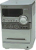
... AC leakage. The "limit" indication is classified as a CLASS 1 LASER product. COMPONENTS IDENTIFIED BY MARK 0 OR DOTTED LINE WITH MARK 0 ON THE SCHEMATIC DIAGRAMS AND IN THE PARTS LIST ARE CRITICAL TO SAFE OPERATION. HCD-NEZ30 Notes on Set 0.15 µF 1.5 kΩ AC voltmeter (0.75 V) Earth Ground Fig.... side of a VOM or battery-operated AC voltmeter. Using an AC voltmeter to use these instruments. 2. SAFETY-RELATED COMPONENT WARNING!! POSANTS QUE PAR DES PIÈCES SONY DONT LES NUMÉROS SONT DONNÉS DANS CE MANUEL OU DANS LES SUPPLÉMENTS PUBLIÉS PAR...
... AC leakage. The "limit" indication is classified as a CLASS 1 LASER product. COMPONENTS IDENTIFIED BY MARK 0 OR DOTTED LINE WITH MARK 0 ON THE SCHEMATIC DIAGRAMS AND IN THE PARTS LIST ARE CRITICAL TO SAFE OPERATION. HCD-NEZ30 Notes on Set 0.15 µF 1.5 kΩ AC voltmeter (0.75 V) Earth Ground Fig.... side of a VOM or battery-operated AC voltmeter. Using an AC voltmeter to use these instruments. 2. SAFETY-RELATED COMPONENT WARNING!! POSANTS QUE PAR DES PIÈCES SONY DONT LES NUMÉROS SONT DONNÉS DANS CE MANUEL OU DANS LES SUPPLÉMENTS PUBLIÉS PAR...
Service Manual
Page 3
... VIEWS 8-1. Cabinet Section 36 8-2. Panel Board Section 38 8-4. AC Board, DC Board Section 41 9. Printed Wiring Board - Mechanical Deck Section 37 8-3. HCD-NEZ30 SECTION 1 Ver. 1.5 SERVICING NOTES NOTES ON HANDLING THE OPTICAL PICK-UP BLOCK OR BASE UNIT The laser diode in the optical pickup.../SUPPLEMENT-1 according to SUPPLEMENT-2 for the PANEL board of printed wiring board, schematic diagram and electrical parts list of UK and East European models. Tuner (FM/AM 11 4. CD Board 20 7-4. on the disc reflective surface by the charged electrostatic load, etc...
... VIEWS 8-1. Cabinet Section 36 8-2. Panel Board Section 38 8-4. AC Board, DC Board Section 41 9. Printed Wiring Board - Mechanical Deck Section 37 8-3. HCD-NEZ30 SECTION 1 Ver. 1.5 SERVICING NOTES NOTES ON HANDLING THE OPTICAL PICK-UP BLOCK OR BASE UNIT The laser diode in the optical pickup.../SUPPLEMENT-1 according to SUPPLEMENT-2 for the PANEL board of printed wiring board, schematic diagram and electrical parts list of UK and East European models. Tuner (FM/AM 11 4. CD Board 20 7-4. on the disc reflective surface by the charged electrostatic load, etc...
Service Manual
Page 19
...' patterns are not indicated.) Caution: Pattern face side: (Conductor Side) Parts face side: (Component Side) Parts on Schematic Diagram: • All capacitors are in Ω and 1/4 W or less unless otherwise specified. • f : internal component. • 2 : nonflammable resistor. • 5 : fusible resistor. • C :... model • Circuit Boards Location PANEL board DC board HCD-NEZ30 Ver. 1.5 CONNECT board AC board CD board MAIN board SHIELD board (EXCEPT UK, East European) HEAD PHONE board TUNER UNIT HCD-NEZ30 19 19 Note on the pattern face side seen from ...
...' patterns are not indicated.) Caution: Pattern face side: (Conductor Side) Parts face side: (Component Side) Parts on Schematic Diagram: • All capacitors are in Ω and 1/4 W or less unless otherwise specified. • f : internal component. • 2 : nonflammable resistor. • 5 : fusible resistor. • C :... model • Circuit Boards Location PANEL board DC board HCD-NEZ30 Ver. 1.5 CONNECT board AC board CD board MAIN board SHIELD board (EXCEPT UK, East European) HEAD PHONE board TUNER UNIT HCD-NEZ30 19 19 Note on the pattern face side seen from ...
Service Manual
Page 21
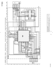
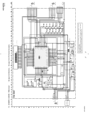
...-MP3 REQ-MP3 ACK-MP3 XLAT VDD SVSS SVDD SENS WFCK XUGF XPCK GFS C2PO SCOR VDD COUT SVSS CD DSP IC201 CXD3014A-201R D C B A VC FEO FEI TEO TEI F E AVSS0 AVDD0 IOVDD1 FRDR .... • See page 25 for IC Block Diagrams. • See page 31 for the CD board of schematic diagram of original service manual/SUPPLEMENT-1 according to SUPPLEMENT-1 for IC Pin Function Description. R451 22k...(LIMIT) OPTICAL PICK-UP BLOCK KSM-213CDP M401 (SPINDLE) M402 (SLED) HCD-NEZ30 Refer to the set of except UK and East European models, refer to either of UK and East European models. SCHEMATIC DIAGRAM -
...-MP3 REQ-MP3 ACK-MP3 XLAT VDD SVSS SVDD SENS WFCK XUGF XPCK GFS C2PO SCOR VDD COUT SVSS CD DSP IC201 CXD3014A-201R D C B A VC FEO FEI TEO TEI F E AVSS0 AVDD0 IOVDD1 FRDR .... • See page 25 for IC Block Diagrams. • See page 31 for the CD board of schematic diagram of original service manual/SUPPLEMENT-1 according to SUPPLEMENT-1 for IC Pin Function Description. R451 22k...(LIMIT) OPTICAL PICK-UP BLOCK KSM-213CDP M401 (SPINDLE) M402 (SLED) HCD-NEZ30 Refer to the set of except UK and East European models, refer to either of UK and East European models. SCHEMATIC DIAGRAM -
Service Manual
Page 23
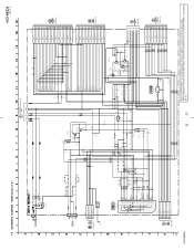
...repairing the set of US and Canadian models, refer to the set. MAIN Section (1/2) - HCD-NEZ30 Ver. 1.1 (Page 24) A1 A2 A4 A5 A6 A7 A8 J321 AUDIO IN R236 ... 100 R391 R392 D324 UDZSTE-174.7B D320 MC2840-T112-1 R521 10k R517 47k D307 1SS355TE CD-R C238 22 50V CD-L C138 22 50V SCOR SENS XLAT MP3-ACK MP3-O-REQ MP3-XLAT MP3-DATA CLK MP3-I-...-R HPGND SP-L SP-L SP-L HP-L HP-L HP-L CN500 13P (Page 24) (Page 24) HCD-NEZ30 23 23 Refer to SUPPLEMENT-1 for the MAIN board of schematic diagram of original service manual/SUPPLEMENT-1 according to either of except US and Canadian models...
...repairing the set of US and Canadian models, refer to the set. MAIN Section (1/2) - HCD-NEZ30 Ver. 1.1 (Page 24) A1 A2 A4 A5 A6 A7 A8 J321 AUDIO IN R236 ... 100 R391 R392 D324 UDZSTE-174.7B D320 MC2840-T112-1 R521 10k R517 47k D307 1SS355TE CD-R C238 22 50V CD-L C138 22 50V SCOR SENS XLAT MP3-ACK MP3-O-REQ MP3-XLAT MP3-DATA CLK MP3-I-...-R HPGND SP-L SP-L SP-L HP-L HP-L HP-L CN500 13P (Page 24) (Page 24) HCD-NEZ30 23 23 Refer to SUPPLEMENT-1 for the MAIN board of schematic diagram of original service manual/SUPPLEMENT-1 according to either of except US and Canadian models...
Service Manual
Page 24
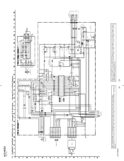
...European models, refer to either of original service manual/ SUPPLEMENT-2 according to the set . 24 SCHEMATIC DIAGRAM - HCD-NEZ30 24 Refer to SUPPLEMENT-1 for the HEAD PHONE board of schematic diagram of except US and Canadian models. MAIN Section (2/2) - • See page 25 for... Waveforms. • See page 25 for IC Block Diagrams. FM 75Ω COAXIAL ANTENNA AM (2/2) R135 100k R235 100k C235 10 50V C135 10 50V CD-L CD...
...European models, refer to either of original service manual/ SUPPLEMENT-2 according to the set . 24 SCHEMATIC DIAGRAM - HCD-NEZ30 24 Refer to SUPPLEMENT-1 for the HEAD PHONE board of schematic diagram of except US and Canadian models. MAIN Section (2/2) - • See page 25 for... Waveforms. • See page 25 for IC Block Diagrams. FM 75Ω COAXIAL ANTENNA AM (2/2) R135 100k R235 100k C235 10 50V C135 10 50V CD-L CD...
Service Manual
Page 27
...refer to either of UK and East European models. SCHEMATIC DIAGRAM - 7-9. LCD801 LIQUID CRYSTAL DISPLAY HCD-NEZ30 Ver. 1.5 COM0 COM1 COM2 COM3 SEG0 SEG1 ...D+4V(SUB) D-GND ACDET POWER-ON I-PWR.MONI M-GND M+10V 1 TAPE MECHANISM DECK BLOCK SUPPLIED WITH THE ASSEMBLED BLOCK 1 REC PACK MOTOR10V R849 4.7k SOL10V COM GND...V GO C811 10 16V 9 C812 470p R815 1k REMOTE CONTROL RECEIVER R805 0 R863 100 R841 1k D806 SLR342 STANDBY O-LED-STBY R842...SO SI SCO OPEN/CLOSE 1 GND 2 FFC804 (Page 24) (NC) S820 CD LID OPEN/CLOSE DETECT HCD-NEZ30 Refer to the set. 27 27 S807 + 31 6 11 34 3 49 ...
...refer to either of UK and East European models. SCHEMATIC DIAGRAM - 7-9. LCD801 LIQUID CRYSTAL DISPLAY HCD-NEZ30 Ver. 1.5 COM0 COM1 COM2 COM3 SEG0 SEG1 ...D+4V(SUB) D-GND ACDET POWER-ON I-PWR.MONI M-GND M+10V 1 TAPE MECHANISM DECK BLOCK SUPPLIED WITH THE ASSEMBLED BLOCK 1 REC PACK MOTOR10V R849 4.7k SOL10V COM GND...V GO C811 10 16V 9 C812 470p R815 1k REMOTE CONTROL RECEIVER R805 0 R863 100 R841 1k D806 SLR342 STANDBY O-LED-STBY R842...SO SI SCO OPEN/CLOSE 1 GND 2 FFC804 (Page 24) (NC) S820 CD LID OPEN/CLOSE DETECT HCD-NEZ30 Refer to the set. 27 27 S807 + 31 6 11 34 3 49 ...

Service Manual
Page 30
... REPLACED" (page 4) in the servicing notes when the entire DC board, D921, R911, R912, R920, T901 or T902 is replaced. (US and Canadian models only) HCD-NEZ30 30 30 SCHEMATIC DIAGRAM - HCD-NEZ30 Ver. 1.5 7-12.
... REPLACED" (page 4) in the servicing notes when the entire DC board, D921, R911, R912, R920, T901 or T902 is replaced. (US and Canadian models only) HCD-NEZ30 30 30 SCHEMATIC DIAGRAM - HCD-NEZ30 Ver. 1.5 7-12.


