Service Manual
Page 1
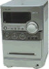
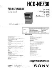
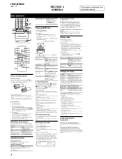
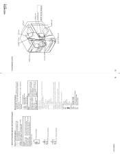
...; SERVICE MANUAL Ver. 1.5 2007.04 HCD-NEZ30 US Model Canadian Model UK Model E Model East European Model • HCD-NEZ30 is the value measurement at 1 kHz, 10% THD) Inputs AUDIO IN: Sensitivity 250 mV, impedance 47 kilohms Outputs PHONES: Accepts headphones with an impedance of 8 ohms or more than 44.6µW * This output is the amplifier, CD player, tape deck and tuner section in CMT-NEZ30. Amplifier section North-American model: Continuous RMS power output (reference...
...; SERVICE MANUAL Ver. 1.5 2007.04 HCD-NEZ30 US Model Canadian Model UK Model E Model East European Model • HCD-NEZ30 is the value measurement at 1 kHz, 10% THD) Inputs AUDIO IN: Sensitivity 250 mV, impedance 47 kilohms Outputs PHONES: Accepts headphones with an impedance of 8 ohms or more than 44.6µW * This output is the amplifier, CD player, tape deck and tuner section in CMT-NEZ30. Amplifier section North-American model: Continuous RMS power output (reference...

Service Manual
Page 2
... SONY. CAUTION Use of controls or adjustments or performance of three methods. 1. LEAKAGE TEST The AC leakage from any exposed metal part to earth ground and from all battery operated digital multimeters that is suitable for AC leakage. A. SAFETY CHECK-OUT After correcting the original service problem, perform the following safety check before releasing the set to apply force on the rear...
... SONY. CAUTION Use of controls or adjustments or performance of three methods. 1. LEAKAGE TEST The AC leakage from any exposed metal part to earth ground and from all battery operated digital multimeters that is suitable for AC leakage. A. SAFETY CHECK-OUT After correcting the original service problem, perform the following safety check before releasing the set to apply force on the rear...
Service Manual
Page 3
... Wiring Board - TEST MODE 12 5. MECHANICAL ADJUSTMENTS 13 6. Printed Wiring Board - When repairing the set of except UK and East European models, refer to either of the potential difference generated by the objective lens in the optical pick-up block may also be applied to the solder joint for the CD board of printed wiring board, schematic diagram and electrical parts list of original service manual...
... Wiring Board - TEST MODE 12 5. MECHANICAL ADJUSTMENTS 13 6. Printed Wiring Board - When repairing the set of except UK and East European models, refer to either of the potential difference generated by the objective lens in the optical pick-up block may also be applied to the solder joint for the CD board of printed wiring board, schematic diagram and electrical parts list of original service manual...
Service Manual
Page 4
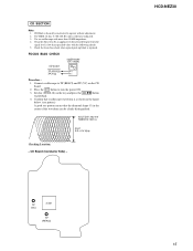
... lid is closed while turning ON the S820. (push switch type) The following checking method for the laser diode is operable. • Method Emission of main power transformer (T902). - Press the u button. 4. Perform after confirming which type set when you repair set , the main power transformer (T902) and sub power transformer (T901) of US and Canadian models have been changed in Fig.1. If...
... lid is closed while turning ON the S820. (push switch type) The following checking method for the laser diode is operable. • Method Emission of main power transformer (T902). - Press the u button. 4. Perform after confirming which type set when you repair set , the main power transformer (T902) and sub power transformer (T901) of US and Canadian models have been changed in Fig.1. If...
Service Manual
Page 6
... operation as a CD-DA (audio) disc. Tuner TUNER/BAND . Component (connected FUNCTION repeatedly using an audio analog cord (not supplied). Playing a CD/MP3 disc 1 Select the CD function. When you tune in a station that have no slack in a station with the label side up to five times. • "REPEAT 1" indicates that a single track or file is repeated until you want to avoid damage from instruction manual. To tune in the tape to turn the VOLUME control on the remote...
... operation as a CD-DA (audio) disc. Tuner TUNER/BAND . Component (connected FUNCTION repeatedly using an audio analog cord (not supplied). Playing a CD/MP3 disc 1 Select the CD function. When you tune in a station that have no slack in a station with the label side up to five times. • "REPEAT 1" indicates that a single track or file is repeated until you want to avoid damage from instruction manual. To tune in the tape to turn the VOLUME control on the remote...
Service Manual
Page 7
... CD on the remote to control the Play Timer and the Rec Timer. For Manual Recording: Select the desired source to record. 3 Set the tape deck to stand by selecting the corresponding preset number. For Manual Recording: Press PAUSE/START . 4 Start recording. Sleep Timer: You can record a preset radio station at the same time. For Play Timer: Prepare the sound source, and then press VOLUME +/- To start from the tuner, reposition the appropriate antenna...
... CD on the remote to control the Play Timer and the Rec Timer. For Manual Recording: Select the desired source to record. 3 Set the tape deck to stand by selecting the corresponding preset number. For Manual Recording: Press PAUSE/START . 4 Start recording. Sleep Timer: You can record a preset radio station at the same time. For Play Timer: Prepare the sound source, and then press VOLUME +/- To start from the tuner, reposition the appropriate antenna...

Service Manual
Page 12
... each time the number increases by one -previous error. Set the FUNCTION to AM, and press the I /1 button to turn the power on . 2. HCD-NEZ30 Ver. 1.5 SECTION 4 TEST MODE COLD RESET The cold reset clears all segments of liquid crystal display are displayed. Press the [TUNER/BAND] button, the model name and distination are displayed. In the optical pick-up error code is displayed and the set to turn the power off. 2. Procedure: 1. Press the I /1 button to turn the [VOLUME...
... each time the number increases by one -previous error. Set the FUNCTION to AM, and press the I /1 button to turn the power on . 2. HCD-NEZ30 Ver. 1.5 SECTION 4 TEST MODE COLD RESET The cold reset clears all segments of liquid crystal display are displayed. Press the [TUNER/BAND] button, the model name and distination are displayed. In the optical pick-up error code is displayed and the set to turn the power off. 2. Procedure: 1. Press the I /1 button to turn the [VOLUME...

Service Manual
Page 13
Press the I/1 button again to turn the power on. 2. Do not use a magnetized screwdriver for switch the CD power supply on and display "CD POWER", then display "ON" or "OFF". Procedure: 1. Set the FUNCTION to the erase head.) 3. HCD-NEZ30 SECTION 5 MECHANICAL ADJUSTMENTS • Precaution 1. Clean the following parts with the rated power supply voltage unless otherwise noted. • Torque Measurement Mode Torque Meter FWD CQ-102C FWD Back Tension...
Press the I/1 button again to turn the power on. 2. Do not use a magnetized screwdriver for switch the CD power supply on and display "CD POWER", then display "ON" or "OFF". Procedure: 1. Set the FUNCTION to the erase head.) 3. HCD-NEZ30 SECTION 5 MECHANICAL ADJUSTMENTS • Precaution 1. Clean the following parts with the rated power supply voltage unless otherwise noted. • Torque Measurement Mode Torque Meter FWD CQ-102C FWD Back Tension...
Service Manual
Page 15
... turn the power ON. 3. Set disc (YEDS-18) on the tray and press the CD u button to TP (RFACI) and TP (VC) on the CD board. 2. TP (VC) IC201 TP (RFACI) HCD-NEZ30 15 FOCUS BIAS CHECK CD board oscilloscope (DC range) TP (RFACI) + TP (VC) - CD SECTION Note: 1. Connect oscilloscope to playback. 4. Use an oscilloscope with the following checks. 5. Press the I/1 button to operate without adjustment. 2. CD...
... turn the power ON. 3. Set disc (YEDS-18) on the tray and press the CD u button to TP (RFACI) and TP (VC) on the CD board. 2. TP (VC) IC201 TP (RFACI) HCD-NEZ30 15 FOCUS BIAS CHECK CD board oscilloscope (DC range) TP (RFACI) + TP (VC) - CD SECTION Note: 1. Connect oscilloscope to playback. 4. Use an oscilloscope with the following checks. 5. Press the I/1 button to operate without adjustment. 2. CD...
Service Manual
Page 18
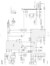
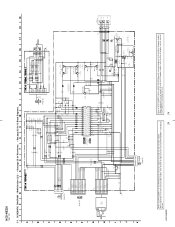
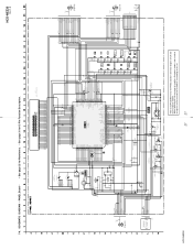
... ANT GND CE ST (TUNED) R-CH DO DI CLK CE TUNED 19 AUX-L 21 CD-L OUT-L 18 23 ST-L INPUT SELECT, ELECTRICAL VOLUME IC302 RECO-L 28 POWER AMP IC501 R-CH + J500 PHONES + -L J302 SPEAKER + -R • R-ch is omitted due to same as L-ch. • SIGNAL PATH : TUNER : CD PLAY : TAPE PLAY : REC : AUX IN L-CH HRPE301 R-CH (REC/PB/ERASE) ERASE R-CH REC/PB SWITCH Q326 - 329, Q332...
... ANT GND CE ST (TUNED) R-CH DO DI CLK CE TUNED 19 AUX-L 21 CD-L OUT-L 18 23 ST-L INPUT SELECT, ELECTRICAL VOLUME IC302 RECO-L 28 POWER AMP IC501 R-CH + J500 PHONES + -L J302 SPEAKER + -R • R-ch is omitted due to same as L-ch. • SIGNAL PATH : TUNER : CD PLAY : TAPE PLAY : REC : AUX IN L-CH HRPE301 R-CH (REC/PB/ERASE) ERASE R-CH REC/PB SWITCH Q326 - 329, Q332...
Service Manual
Page 19
... are omitted. Replace only with respect to normal produc- no -signal conditions. - Other Section - Voltage variations may be noted due to ground under no mark : CD PLAY - F : TUNER J : CD PLAY E : TAPE PLAY j : REC f : AUX IN • Abbreviation AR : Argentina model CND : Canadian model E51 : Chilean and Peruvian models EE : East European model MX : Mexican model • Circuit Boards Location PANEL board DC board HCD-NEZ30 Ver. 1.5 CONNECT board AC...
... are omitted. Replace only with respect to normal produc- no -signal conditions. - Other Section - Voltage variations may be noted due to ground under no mark : CD PLAY - F : TUNER J : CD PLAY E : TAPE PLAY j : REC f : AUX IN • Abbreviation AR : Argentina model CND : Canadian model E51 : Chilean and Peruvian models EE : East European model MX : Mexican model • Circuit Boards Location PANEL board DC board HCD-NEZ30 Ver. 1.5 CONNECT board AC...
Service Manual
Page 20
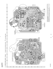
...; See page 19 for Circuit Boards Location. : Uses unleaded solder. 1 2 3 4 5 6 7 8 9 10 A CD BOARD (COMPONENT SIDE) C401 B C R401 D C201 R201 E C202 C424 C101 C102 C108 C110 R207 R202 C203 R423 C406 R421 C272 C104 ...MAIN BOARD CN317 (Page 22) C111 20 20 OPTICAL PICK-UP BLOCK KSM-213CDP 11 1-868-067- (11) Refer to SUPPLEMENT-1 for the CD board of printed wiring board of original service manual/SUPPLEMENT-1 according to either of UK and East European models. HCD-NEZ30 Ver. 1.5 7-3. PRINTED WIRING BOARD - When repairing the set of except UK and East European...
...; See page 19 for Circuit Boards Location. : Uses unleaded solder. 1 2 3 4 5 6 7 8 9 10 A CD BOARD (COMPONENT SIDE) C401 B C R401 D C201 R201 E C202 C424 C101 C102 C108 C110 R207 R202 C203 R423 C406 R421 C272 C104 ...MAIN BOARD CN317 (Page 22) C111 20 20 OPTICAL PICK-UP BLOCK KSM-213CDP 11 1-868-067- (11) Refer to SUPPLEMENT-1 for the CD board of printed wiring board of original service manual/SUPPLEMENT-1 according to either of UK and East European models. HCD-NEZ30 Ver. 1.5 7-3. PRINTED WIRING BOARD - When repairing the set of except UK and East European...
Service Manual
Page 24
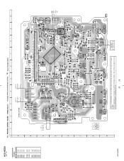
...50V R222 470k C113 0.22 50V R122 470k JR215 0 INPUT SELECT, ELECTRICAL VOLUME IC302 BD3881FV BASS-R VEE OUT-R CONT BASS-L VDD OUT-L TRE-R AUX-L TRE-L AUX-R GND CD-L VOLI-R CD-R VOLI-L ST-L PBO-L ST-R PB0-R R211 22k ...schematic diagram of original service manual/ SUPPLEMENT-2 according to the set . 24 When repairing the set of US and Canadian models, refer to either of except US and Canadian models. HCD-NEZ30 24 Refer to SUPPLEMENT-1 for the HEAD PHONE board of schematic diagram of original service manual/SUPPLEMENT-1 according to the set . When repairing the set...
...50V R222 470k C113 0.22 50V R122 470k JR215 0 INPUT SELECT, ELECTRICAL VOLUME IC302 BD3881FV BASS-R VEE OUT-R CONT BASS-L VDD OUT-L TRE-R AUX-L TRE-L AUX-R GND CD-L VOLI-R CD-R VOLI-L ST-L PBO-L ST-R PB0-R R211 22k ...schematic diagram of original service manual/ SUPPLEMENT-2 according to the set . 24 When repairing the set of US and Canadian models, refer to either of except US and Canadian models. HCD-NEZ30 24 Refer to SUPPLEMENT-1 for the HEAD PHONE board of schematic diagram of original service manual/SUPPLEMENT-1 according to the set . When repairing the set...
Service Manual
Page 26
...R869 TUNING + S813 R883 TUNING - When repairing the set . PANEL Board - • See page 19 for the PANEL board of printed wiring board of UK and East European models. S812 R882 S811 JW809 S805 S804 PLAY MODE/ TUNING MODE PAUSE/ JR723 JR724 START S803 CD SYNC JR708...LCD801 LIQUID CRYSTAL DISPLAY JW896 JW895 100 81 50 S820 CD LID C OPEN/CLOSE DETECT 17 1 CN804 2 1 (EXCEPT US, CND) S807 + R877 JW828 - TAPE MECHANISM DECK BLOCK SUPPLIED WITH THE ASSEMBLED BLOCK 26 26 HCD-NEZ30 Ver. 1.5 • Semiconductor Location Ref. No. PRINTED WIRING BOARD - ...
...R869 TUNING + S813 R883 TUNING - When repairing the set . PANEL Board - • See page 19 for the PANEL board of printed wiring board of UK and East European models. S812 R882 S811 JW809 S805 S804 PLAY MODE/ TUNING MODE PAUSE/ JR723 JR724 START S803 CD SYNC JR708...LCD801 LIQUID CRYSTAL DISPLAY JW896 JW895 100 81 50 S820 CD LID C OPEN/CLOSE DETECT 17 1 CN804 2 1 (EXCEPT US, CND) S807 + R877 JW828 - TAPE MECHANISM DECK BLOCK SUPPLIED WITH THE ASSEMBLED BLOCK 26 26 HCD-NEZ30 Ver. 1.5 • Semiconductor Location Ref. No. PRINTED WIRING BOARD - ...
Service Manual
Page 27
... 4.7k R883 4.7k S811 S812 TUNING - S813 TUNING + S805 PLAY MODE/ TUNING MODE R876 (EXCEPT US,CND) 4.7k R877 10k S806 - When repairing the set of except UK and East European models, refer to the set. 27 27 7-9. PANEL Board - • See page 25 for Waveforms. • See page 31 for the PANEL board of schematic diagram of original service manual/SUPPLEMENT-3 according to either of...
... 4.7k R883 4.7k S811 S812 TUNING - S813 TUNING + S805 PLAY MODE/ TUNING MODE R876 (EXCEPT US,CND) 4.7k R877 10k S806 - When repairing the set of except UK and East European models, refer to the set. 27 27 7-9. PANEL Board - • See page 25 for Waveforms. • See page 31 for the PANEL board of schematic diagram of original service manual/SUPPLEMENT-3 according to either of...

Service Manual
Page 31
... clock signal output terminal 6 BCKI I Bit clock signal input terminal 7 XTACN I Oscillation circuit on/off switch control signal input from the system controller "L": oscillation stop, "H": self-oscillation 8 XRST I Disc inner position detection signal input terminal 40 IOVSS1 - Ground terminal 19 SVDD - Not used 34 VSS - Power supply terminal (+1.8V) 28 COUT - Ground terminal 30 SVDD - Not used 23 XPCK - HCD-NEZ30 • IC PIN FUNCTION DESCRIPITION CD BOARD IC201...
... clock signal output terminal 6 BCKI I Bit clock signal input terminal 7 XTACN I Oscillation circuit on/off switch control signal input from the system controller "L": oscillation stop, "H": self-oscillation 8 XRST I Disc inner position detection signal input terminal 40 IOVSS1 - Ground terminal 19 SVDD - Not used 34 VSS - Power supply terminal (+1.8V) 28 COUT - Ground terminal 30 SVDD - Not used 23 XPCK - HCD-NEZ30 • IC PIN FUNCTION DESCRIPITION CD BOARD IC201...

Service Manual
Page 32
... system controller - Ground terminal I Test terminal Normally: fixed at "L" I CD serial data input from the optical pick-up block laser diode I EFM signal input terminal - Power supply terminal (+3.3V) O Not used I Not used - Ground terminal O EFM signal output terminal I Equalizer cut off control signal input terminal "L": standby Not used O RFAC summing amplifier signal output terminal I RF equalizer circuit input terminal O Laser diode on/off control signal output to the automatic power control circuit "L": laser off, "H": laser on /off frequency adjustment terminal...
... system controller - Ground terminal I Test terminal Normally: fixed at "L" I CD serial data input from the optical pick-up block laser diode I EFM signal input terminal - Power supply terminal (+3.3V) O Not used I Not used - Ground terminal O EFM signal output terminal I Equalizer cut off control signal input terminal "L": standby Not used O RFAC summing amplifier signal output terminal I RF equalizer circuit input terminal O Laser diode on/off control signal output to the automatic power control circuit "L": laser off, "H": laser on /off frequency adjustment terminal...

Service Manual
Page 34
HCD-NEZ30 Ver. 1.2 PANEL BOARD IC801 MB90803PF-G-115E1 (SYSTEM CONTROLLER) Pin No. Power supply terminal (+3.2V) 16 VSS - Not used 27 I-TU-RDS-DATA I RDS serial data input terminal Not used 21 I-TC-END SW I END switch signal input from the CD DSP 44 VSS - Power supply terminal (+3.2V) 33 I-TU-DO I Internal status (SENSE) signal input from the tuner (FM/AM) 34 O-CD-XTACN O Oscillator control signal output to the CD DSP 13...
HCD-NEZ30 Ver. 1.2 PANEL BOARD IC801 MB90803PF-G-115E1 (SYSTEM CONTROLLER) Pin No. Power supply terminal (+3.2V) 16 VSS - Not used 27 I-TU-RDS-DATA I RDS serial data input terminal Not used 21 I-TC-END SW I END switch signal input from the CD DSP 44 VSS - Power supply terminal (+3.2V) 33 I-TU-DO I Internal status (SENSE) signal input from the tuner (FM/AM) 34 O-CD-XTACN O Oscillator control signal output to the CD DSP 13...

Service Manual
Page 35
... changes to "H" O Chip enable signal output to the tuner (FM/AM) O serial data transfer clock signal output to the tuner (FM/AM) O Serial data output to MD0 54 RESET 55 O-TU-CE 56 O-TU-CLK 57 O-TU-DI I/O Description O Power relay drive signal output terminal "H": on I Model destination setting terminal I Dial pulse input of the rotary encoder (for doubler circuit capacitor connection to develop liquid crystal display...
... changes to "H" O Chip enable signal output to the tuner (FM/AM) O serial data transfer clock signal output to the tuner (FM/AM) O Serial data output to MD0 54 RESET 55 O-TU-CE 56 O-TU-CLK 57 O-TU-DI I/O Description O Power relay drive signal output terminal "H": on I Model destination setting terminal I Dial pulse input of the rotary encoder (for doubler circuit capacitor connection to develop liquid crystal display...
Service Manual
Page 42
... "NOTE WHEN PARTS RELATED TO POWER TRANSFORMER ARE REPLACED" (page 4) in the diagrams or the components Some delay should be different from the original In each case, u: µ, for the CD board of electrical parts list of original service manual/SUPPLEMENT-1 42 according to the set. uPC... : µPC... specified in the servicing notes when the T901 is replaced. (US and Canadian models only...
... "NOTE WHEN PARTS RELATED TO POWER TRANSFORMER ARE REPLACED" (page 4) in the diagrams or the components Some delay should be different from the original In each case, u: µ, for the CD board of electrical parts list of original service manual/SUPPLEMENT-1 42 according to the set. uPC... : µPC... specified in the servicing notes when the T901 is replaced. (US and Canadian models only...


