Service Manual
Page 1
...Approx. 164 × 235 × 265 mm Mass (excl. COMPACT DISC DECK RECEIVER 9-887-030-06 2007D05-1 © 2007.04 Sony Corporation Personal Audio Division Published by Sony Techno Create Corporation CD Section TAPE Section Model Name Using Similar Mechanism Base Unit Name Optical Pick-up ... to rated output. SERVICE MANUAL Ver. 1.5 2007.04 HCD-NEZ30 US Model Canadian Model UK Model E Model East European Model • HCD-NEZ30 is the value measurement at a distance of 8 ohms or more than 44.6µW * This output is the amplifier, CD player, tape deck and tuner section in CMT...
...Approx. 164 × 235 × 265 mm Mass (excl. COMPACT DISC DECK RECEIVER 9-887-030-06 2007D05-1 © 2007.04 Sony Corporation Personal Audio Division Published by Sony Techno Create Corporation CD Section TAPE Section Model Name Using Similar Mechanism Base Unit Name Optical Pick-up ... to rated output. SERVICE MANUAL Ver. 1.5 2007.04 HCD-NEZ30 US Model Canadian Model UK Model E Model East European Model • HCD-NEZ30 is the value measurement at a distance of 8 ohms or more than 44.6µW * This output is the amplifier, CD player, tape deck and tuner section in CMT...

Service Manual
Page 2
...voltmeter (0.75 V) Earth Ground Fig. This marking is classified as described below. REPLACE THESE COMPONENTS WITH SONY PARTS WHOSE PART NUMBERS APPEAR AS SHOWN IN THIS MANUAL OR IN SUPPLEMENTS PUBLISHED BY SONY. 2 ATTENTION AU COMPOSANT AYANT RAPPORT À LA SÉCURITÉ! A battery-operated AC ...;ROS SONT DONNÉS DANS CE MANUEL OU DANS LES SUPPLÉMENTS PUBLIÉS PAR SONY. HCD-NEZ30 Notes on chip component replacement • Never reuse a disconnected chip component. • Notice that have an accurate low-voltage scale. LEAKAGE TEST The AC leakage from ...
...voltmeter (0.75 V) Earth Ground Fig. This marking is classified as described below. REPLACE THESE COMPONENTS WITH SONY PARTS WHOSE PART NUMBERS APPEAR AS SHOWN IN THIS MANUAL OR IN SUPPLEMENTS PUBLISHED BY SONY. 2 ATTENTION AU COMPOSANT AYANT RAPPORT À LA SÉCURITÉ! A battery-operated AC ...;ROS SONT DONNÉS DANS CE MANUEL OU DANS LES SUPPLÉMENTS PUBLIÉS PAR SONY. HCD-NEZ30 Notes on chip component replacement • Never reuse a disconnected chip component. • Notice that have an accurate low-voltage scale. LEAKAGE TEST The AC leakage from ...
Service Manual
Page 3
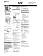
...CD board of printed wiring board, schematic diagram and electrical parts list of UK and East European models. When repairing the set of except UK and East European models, refer to either of except US and Canadian models. HCD-NEZ30... UK and East European models. Disassembly Flow 8 3-2. Front Panel Section 10 3-6. Mechanical Deck (CMAL5Z235A 10 3-7. Block Diagram - Printed Wiring Board - POWER SUPPLY Section - ........ ...repair, pay attention to electrostatic break-down because of original service manual/SUPPLEMENT-3 according to SUPPLEMENT-3 for the HEAD PHONE board of ...
...CD board of printed wiring board, schematic diagram and electrical parts list of UK and East European models. When repairing the set of except UK and East European models, refer to either of except US and Canadian models. HCD-NEZ30... UK and East European models. Disassembly Flow 8 3-2. Front Panel Section 10 3-6. Mechanical Deck (CMAL5Z235A 10 3-7. Block Diagram - Printed Wiring Board - POWER SUPPLY Section - ........ ...repair, pay attention to electrostatic break-down because of original service manual/SUPPLEMENT-3 according to SUPPLEMENT-3 for the HEAD PHONE board of ...
Service Manual
Page 6
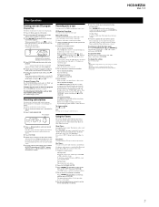
...unit) . on the remote (or turn off to avoid damage from instruction manual. Playing a CD/MP3 disc 1 Select the CD function. You can only play mode. - on the disc), shuffl...control on the remote. changing the CD power manage function Notes on the unit again to set the clock 1 Turn on the CD compartment. HCD-NEZ30 Ver. 1.1 SECTION 2 GENERAL This... (0 to 9), and symbols Using optional audio components To connect an optional headphones Connect headphones to avoid damaging the tape or the tape deck. Scanning stops automatically when a station is no...
...unit) . on the remote (or turn off to avoid damage from instruction manual. Playing a CD/MP3 disc 1 Select the CD function. You can only play mode. - on the disc), shuffl...control on the remote. changing the CD power manage function Notes on the unit again to set the clock 1 Turn on the CD compartment. HCD-NEZ30 Ver. 1.1 SECTION 2 GENERAL This... (0 to 9), and symbols Using optional audio components To connect an optional headphones Connect headphones to avoid damaging the tape or the tape deck. Scanning stops automatically when a station is no...
Service Manual
Page 7
...program additional tracks or files, up to 20 FM and 10 AM stations. HCD-NEZ30 Ver. 1.1 7 Use buttons on the unit to control tape recording. 1 Load a recordable...you cannot listen to other stations. When recording a folder from a sound source, including connected audio components. While recording, you want to record facing forward. 2 Prepare the recording source. If you ... CD Synchro Recording: You can fall asleep to music. repeatedly to stand by selecting the corresponding preset number. For Manual Recording: Select the desired source to record. 3 Set the tape deck ...
...program additional tracks or files, up to 20 FM and 10 AM stations. HCD-NEZ30 Ver. 1.1 7 Use buttons on the unit to control tape recording. 1 Load a recordable...you cannot listen to other stations. When recording a folder from a sound source, including connected audio components. While recording, you want to record facing forward. 2 Prepare the recording source. If you ... CD Synchro Recording: You can fall asleep to music. repeatedly to stand by selecting the corresponding preset number. For Manual Recording: Select the desired source to record. 3 Set the tape deck ...

Service Manual
Page 12
...on . 2. The second digit from this case, HCD-NEZXX) 5. Each time a key is pressed, the numerical value corresponding to the customer. Procedure: 1. HCD-NEZ30 Ver. 1.5 SECTION 4 TEST MODE COLD RESET The ... way Playback operation is under way Pause operation is under way Playback manual search operation is under way Pause manual search operation is under way Start operation in progress TOC read ) ...No. While depressing the [TUNER/BAND] button, press the I /1 button to CD. 2. While pressing the [DSGX] button, press the CD u button and turn the power off. 2. The 5th and 6th digit from...
...on . 2. The second digit from this case, HCD-NEZXX) 5. Each time a key is pressed, the numerical value corresponding to the customer. Procedure: 1. HCD-NEZ30 Ver. 1.5 SECTION 4 TEST MODE COLD RESET The ... way Playback operation is under way Pause operation is under way Playback manual search operation is under way Pause manual search operation is under way Start operation in progress TOC read ) ...No. While depressing the [TUNER/BAND] button, press the I /1 button to CD. 2. While pressing the [DSGX] button, press the CD u button and turn the power off. 2. The 5th and 6th digit from...
Service Manual
Page 20
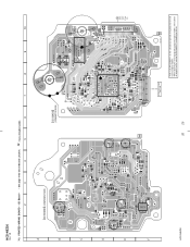
When repairing the set of except UK and East European models, refer to the set. HCD-NEZ30 Ver. 1.5 7-3. CD Board - • See page 19 for Circuit Boards Location. : Uses unleaded solder. 1 2 3 4 5 6 7 8 9 10 A CD BOARD (COMPONENT SIDE) C401 B C R401 D C201 R201 E C202 C424 C101 C102 C108 C110 R207 R202 ...CN317 (Page 22) C111 20 20 OPTICAL PICK-UP BLOCK KSM-213CDP 11 1-868-067- (11) Refer to SUPPLEMENT-1 for the CD board of printed wiring board of original service manual/SUPPLEMENT-1 according to either of UK and East European models. PRINTED WIRING BOARD -
When repairing the set of except UK and East European models, refer to the set. HCD-NEZ30 Ver. 1.5 7-3. CD Board - • See page 19 for Circuit Boards Location. : Uses unleaded solder. 1 2 3 4 5 6 7 8 9 10 A CD BOARD (COMPONENT SIDE) C401 B C R401 D C201 R201 E C202 C424 C101 C102 C108 C110 R207 R202 ...CN317 (Page 22) C111 20 20 OPTICAL PICK-UP BLOCK KSM-213CDP 11 1-868-067- (11) Refer to SUPPLEMENT-1 for the CD board of printed wiring board of original service manual/SUPPLEMENT-1 according to either of UK and East European models. PRINTED WIRING BOARD -
Service Manual
Page 21
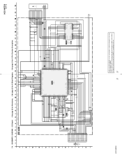
...8226; See page 25 for Waveforms. • See page 25 for IC Block Diagrams. • See page 31 for the CD board of schematic diagram of original service manual/SUPPLEMENT-1 according to SUPPLEMENT-1 for IC Pin Function Description. CH1PUTF CH1OUTR CH2OUTF CH2OUTR POWVCC CNF4 GND C224 0.1 FOCUS/TRUCKING COIL ...CH3OUTF CH3OUTR POWVCC MUTE GND C405 0.1 SPSP+ SLSL+ C406 0.1 S201 (LIMIT) OPTICAL PICK-UP BLOCK KSM-213CDP M401 (SPINDLE) M402 (SLED) HCD-NEZ30 Refer to the set of except UK and East European models, refer to either of UK and East European models. R451 22k TP2 R452 10k...
...8226; See page 25 for Waveforms. • See page 25 for IC Block Diagrams. • See page 31 for the CD board of schematic diagram of original service manual/SUPPLEMENT-1 according to SUPPLEMENT-1 for IC Pin Function Description. CH1PUTF CH1OUTR CH2OUTF CH2OUTR POWVCC CNF4 GND C224 0.1 FOCUS/TRUCKING COIL ...CH3OUTF CH3OUTR POWVCC MUTE GND C405 0.1 SPSP+ SLSL+ C406 0.1 S201 (LIMIT) OPTICAL PICK-UP BLOCK KSM-213CDP M401 (SPINDLE) M402 (SLED) HCD-NEZ30 Refer to the set of except UK and East European models, refer to either of UK and East European models. R451 22k TP2 R452 10k...
Service Manual
Page 22
... LP302 10 11 R224 JW217 JW221 JW161 C360 R340 R339 R385 R371 R369 R376 R230 - HCD-NEZ30 When repairing the set of US and Canadian models, refer to either of original service manual/ SUPPLEMENT-2 according to the set . 22 22 Refer to SUPPLEMENT-1 for the MAIN board...-2 for Circuit Boards Location. : Uses unleaded solder. 1 2 3 4 5 6 7 8 9 10 11 12 13 14 15 MAIN BOARD A (Page 26) D PANEL BOARD (Page 20) A CD BOARD CN102 (Page 28) B DC BOARD CN903 C354 Q344 R312 C367 R138 E C217 R226 C221 R225 R125 R304 JW147 JW137 JW138 JW237 JW136 JW135 JW152...
... LP302 10 11 R224 JW217 JW221 JW161 C360 R340 R339 R385 R371 R369 R376 R230 - HCD-NEZ30 When repairing the set of US and Canadian models, refer to either of original service manual/ SUPPLEMENT-2 according to the set . 22 22 Refer to SUPPLEMENT-1 for the MAIN board...-2 for Circuit Boards Location. : Uses unleaded solder. 1 2 3 4 5 6 7 8 9 10 11 12 13 14 15 MAIN BOARD A (Page 26) D PANEL BOARD (Page 20) A CD BOARD CN102 (Page 28) B DC BOARD CN903 C354 Q344 R312 C367 R138 E C217 R226 C221 R225 R125 R304 JW147 JW137 JW138 JW237 JW136 JW135 JW152...
Service Manual
Page 23
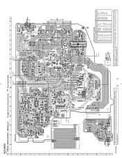
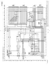
... R505 47k R506 1k R385 1k R386 100 R391 R392 D324 UDZSTE-174.7B D320 MC2840-T112-1 R521 10k R517 47k D307 1SS355TE CD-R C238 22 50V CD-L C138 22 50V SCOR SENS XLAT MP3-ACK MP3-O-REQ MP3-XLAT MP3-DATA CLK MP3-I-REQ XRST XTACN C366 220p MP3-SSTB... SP-R HP-R HP-R HP-R HPGND SP-L SP-L SP-L HP-L HP-L HP-L CN500 13P (Page 24) (Page 24) HCD-NEZ30 23 23 Refer to SUPPLEMENT-1 for the MAIN board of schematic diagram of original service manual/SUPPLEMENT-1 according to either of except US and Canadian models. SCHEMATIC DIAGRAM - MAIN Section (1/2) - When repairing the set...
... R505 47k R506 1k R385 1k R386 100 R391 R392 D324 UDZSTE-174.7B D320 MC2840-T112-1 R521 10k R517 47k D307 1SS355TE CD-R C238 22 50V CD-L C138 22 50V SCOR SENS XLAT MP3-ACK MP3-O-REQ MP3-XLAT MP3-DATA CLK MP3-I-REQ XRST XTACN C366 220p MP3-SSTB... SP-R HP-R HP-R HP-R HPGND SP-L SP-L SP-L HP-L HP-L HP-L CN500 13P (Page 24) (Page 24) HCD-NEZ30 23 23 Refer to SUPPLEMENT-1 for the MAIN board of schematic diagram of original service manual/SUPPLEMENT-1 according to either of except US and Canadian models. SCHEMATIC DIAGRAM - MAIN Section (1/2) - When repairing the set...
Service Manual
Page 24
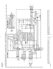
HCD-NEZ30 Ver. 1.5 7-7. MAIN Section (2/2) - • See page 25 for Waveforms. • See page 25 for IC Block Diagrams. FM 75Ω COAXIAL ANTENNA AM (2/2) R135 100k R235 100k C235 10 50V C135 10 50V CD-L CD-R R226 0 R126 0 R125 22k R225 22k R232 1k R233 0 R228 1k R132 C233 R243 1k 0....of except US and Canadian models. When repairing the set of except UK and East European models, refer to either of original service manual/ SUPPLEMENT-2 according to the set . 24 SCHEMATIC DIAGRAM - When repairing the set of US and Canadian models, refer to either of original service...
HCD-NEZ30 Ver. 1.5 7-7. MAIN Section (2/2) - • See page 25 for Waveforms. • See page 25 for IC Block Diagrams. FM 75Ω COAXIAL ANTENNA AM (2/2) R135 100k R235 100k C235 10 50V C135 10 50V CD-L CD-R R226 0 R126 0 R125 22k R225 22k R232 1k R233 0 R228 1k R132 C233 R243 1k 0....of except US and Canadian models. When repairing the set of except UK and East European models, refer to either of original service manual/ SUPPLEMENT-2 according to the set . 24 SCHEMATIC DIAGRAM - When repairing the set of US and Canadian models, refer to either of original service...
Service Manual
Page 26
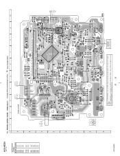
...PRINTED WIRING BOARD - PANEL Board - • See page 19 for the PANEL board of printed wiring board of original service manual/SUPPLEMENT-3 according to SUPPLEMENT-3 for Circuit Boards Location. : Uses unleaded solder. 1 2 3 4 5 6 7 8 ...R831 B R724 JR713 R824 R825 R826 LCD801 LIQUID CRYSTAL DISPLAY JW896 JW895 100 81 50 S820 CD LID C OPEN/CLOSE DETECT 17 1 CN804 2 1 (EXCEPT US, CND) S807 + ... E-9 IC803 D-9 Q801 C-8 Q802 G-5 Q803 H-5 Q804 G-5 Q805 G-5 Q807 B-8 Q808 C-4 HCD-NEZ30 7-8. TAPE MECHANISM DECK BLOCK SUPPLIED WITH THE ASSEMBLED BLOCK 26 26 No...
...PRINTED WIRING BOARD - PANEL Board - • See page 19 for the PANEL board of printed wiring board of original service manual/SUPPLEMENT-3 according to SUPPLEMENT-3 for Circuit Boards Location. : Uses unleaded solder. 1 2 3 4 5 6 7 8 ...R831 B R724 JR713 R824 R825 R826 LCD801 LIQUID CRYSTAL DISPLAY JW896 JW895 100 81 50 S820 CD LID C OPEN/CLOSE DETECT 17 1 CN804 2 1 (EXCEPT US, CND) S807 + ... E-9 IC803 D-9 Q801 C-8 Q802 G-5 Q803 H-5 Q804 G-5 Q805 G-5 Q807 B-8 Q808 C-4 HCD-NEZ30 7-8. TAPE MECHANISM DECK BLOCK SUPPLIED WITH THE ASSEMBLED BLOCK 26 26 No...
Service Manual
Page 27
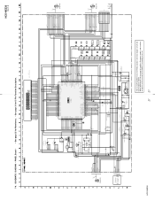
...POWER-ON I-PWR.MONI M-GND M+10V 1 TAPE MECHANISM DECK BLOCK SUPPLIED WITH THE ASSEMBLED BLOCK 1 REC PACK MOTOR10V ... 9 C812 470p R815 1k REMOTE CONTROL RECEIVER R805 0 R863 100 R841 1k D806... FFC804 (Page 24) (NC) S820 CD LID OPEN/CLOSE DETECT HCD-NEZ30 Refer to SUPPLEMENT-3 for IC Pin Function... Description. When repairing the set of except UK and East European models, refer to the set. 27 27 PANEL Board - • See page 25 for Waveforms. • See page 31 for the PANEL board of schematic diagram of original service manual...
...POWER-ON I-PWR.MONI M-GND M+10V 1 TAPE MECHANISM DECK BLOCK SUPPLIED WITH THE ASSEMBLED BLOCK 1 REC PACK MOTOR10V ... 9 C812 470p R815 1k REMOTE CONTROL RECEIVER R805 0 R863 100 R841 1k D806... FFC804 (Page 24) (NC) S820 CD LID OPEN/CLOSE DETECT HCD-NEZ30 Refer to SUPPLEMENT-3 for IC Pin Function... Description. When repairing the set of except UK and East European models, refer to the set. 27 27 PANEL Board - • See page 25 for Waveforms. • See page 31 for the PANEL board of schematic diagram of original service manual...
Service Manual
Page 42
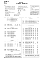
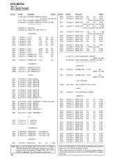
...components Some delay should be different from the original In each case, u: µ, for routine service. METAL: Metal-film resistor. • CAPACITORS METAL OXIDE: Metal oxide-film resistor. When indicating parts by mark 0 or dotted line with part number specified. Ref. HCD-NEZ30 Ver. 1.5 AC CD... in ohms. uPD... : µPD... uPC... : µPC... Replace only with mark 0 are critical for the CD board of electrical parts list of original service manual/SUPPLEMENT-1 42 according to the set . Description A-1158-137-A AC BOARD, COMPLETE (US, CND) A-1158-561-A AC BOARD...
...components Some delay should be different from the original In each case, u: µ, for routine service. METAL: Metal-film resistor. • CAPACITORS METAL OXIDE: Metal oxide-film resistor. When indicating parts by mark 0 or dotted line with part number specified. Ref. HCD-NEZ30 Ver. 1.5 AC CD... in ohms. uPD... : µPD... uPC... : µPC... Replace only with mark 0 are critical for the CD board of electrical parts list of original service manual/SUPPLEMENT-1 42 according to the set . Description A-1158-137-A AC BOARD, COMPLETE (US, CND) A-1158-561-A AC BOARD...
Service Manual
Page 44
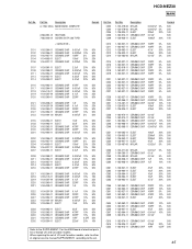
... 10K 5% 1/10W R548 1-216-833-11 METAL CHIP 10K 5% 1/10W Refer to SUPPLEMENT-2 for the HEAD PHONE board of electrical parts list of original service manual/SUPPLEMENT-2 according to either of UK and East European models. Part No. When repairing the set of except UK and East European models, refer to... 0.1uF 25V < CONNECTOR > CN900 1-568-828-11 CONNECTOR, FFC 9P CN902 1-819-135-11 PIN, CONNECTOR 7P CN903 1-819-132-11 PIN, CONNECTOR 4P Ref. HCD-NEZ30 Ver. 1.5 DC HEAD PHONE Ref. R902 R911 R911 R912 Part No. No. No.
... 10K 5% 1/10W R548 1-216-833-11 METAL CHIP 10K 5% 1/10W Refer to SUPPLEMENT-2 for the HEAD PHONE board of electrical parts list of original service manual/SUPPLEMENT-2 according to either of UK and East European models. Part No. When repairing the set of except UK and East European models, refer to... 0.1uF 25V < CONNECTOR > CN900 1-568-828-11 CONNECTOR, FFC 9P CN902 1-819-135-11 PIN, CONNECTOR 7P CN903 1-819-132-11 PIN, CONNECTOR 4P Ref. HCD-NEZ30 Ver. 1.5 DC HEAD PHONE Ref. R902 R911 R911 R912 Part No. No. No.
Service Manual
Page 45
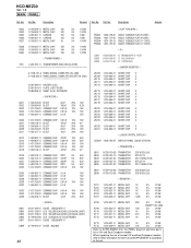
...% 16V Refer to the set of US and Canadian models, refer to either of original service manual/SUPPLEMENT-1 according to the SUPPLEMENT-1 for the MAIN board of electrical parts list of except US and Canadian models. HCD-NEZ30 MAIN Ref. Part No. Description 1-130-479-00 1-130-479-00 1-126-934-11 1-162...
...% 16V Refer to the set of US and Canadian models, refer to either of original service manual/SUPPLEMENT-1 according to the SUPPLEMENT-1 for the MAIN board of electrical parts list of except US and Canadian models. HCD-NEZ30 MAIN Ref. Part No. Description 1-130-479-00 1-130-479-00 1-126-934-11 1-162...
Service Manual
Page 48
... 5% 1/10W 5% 1/10W Refer to SUPPLEMENT-3 for the PANEL board of electrical parts list of original service manual/SUPPLEMENT-3 according to the set of except UK and East European models, refer to either of UK and East European models. HCD-NEZ30 Ver. 1.5 MAIN PANEL Ref. Part No. When repairing the set . Description Remark Ref.
... 5% 1/10W 5% 1/10W Refer to SUPPLEMENT-3 for the PANEL board of electrical parts list of original service manual/SUPPLEMENT-3 according to the set of except UK and East European models, refer to either of UK and East European models. HCD-NEZ30 Ver. 1.5 MAIN PANEL Ref. Part No. When repairing the set . Description Remark Ref.

