
Operating Instructions
Page 1
...FI Component System Operating Instructions GB Owner's Record The model and serial numbers are marketed by some that do not conform to the point of cable entry as practical. Record these numbers in a station with an adaptor). These limits are some record companies. As an ENERGY STAR® partner, Sony...a wall socket. Reorient or relocate the receiving antenna. - You are unavailable: - ... the system securely When carrying this product will not occur in this manual could ... - Model No Serial No CMT-HPR90 © 2006 Sony Corporation Printed in Power Saving Mode,...
...FI Component System Operating Instructions GB Owner's Record The model and serial numbers are marketed by some that do not conform to the point of cable entry as practical. Record these numbers in a station with an adaptor). These limits are some record companies. As an ENERGY STAR® partner, Sony...a wall socket. Reorient or relocate the receiving antenna. - You are unavailable: - ... the system securely When carrying this product will not occur in this manual could ... - Model No Serial No CMT-HPR90 © 2006 Sony Corporation Printed in Power Saving Mode,...

Operating Instructions
Page 2
... Preset number 3 Press +/- repeatedly to select your nearest Sony dealer. The demonstration disappears. The STANDBY indicator remains lit after...the sound source. Tuner Severe hum or noise, or stations cannot be received. • Connect the antenna properly. • Find a location and...PHONES (stereo mini jack): accepts headphones with 7 mm aperture. CD/MP3 player The sound skips, or the disc will turn off the system. 2 While...manually. You cannot change the setting Start over , or when you use any solid object or liquid get into the system, unplug the system...
... Preset number 3 Press +/- repeatedly to select your nearest Sony dealer. The demonstration disappears. The STANDBY indicator remains lit after...the sound source. Tuner Severe hum or noise, or stations cannot be received. • Connect the antenna properly. • Find a location and...PHONES (stereo mini jack): accepts headphones with 7 mm aperture. CD/MP3 player The sound skips, or the disc will turn off the system. 2 While...manually. You cannot change the setting Start over , or when you use any solid object or liquid get into the system, unplug the system...

Service Manual
Page 1
..., impedance of 47 kilohms Outputs PHONES (stereo mini jack): accepts headphones with an impedance of 8 ohms or more SPEAKER: accepts impedance of 4 ohms CD player section System: Compact disc and digital audio system Laser Diode Properties Emission Duration: Continuous Laser Output..., both channels driven, from Dolby Laboratories. HCD-HPR90/HPR99XM SERVICE MANUAL Ver. 1.2 2007.01 US Model Canadian Model HCD-HPR90/HPR99XM E Model Australian Model HCD-HPR90 • HCD-HPR90 is the amplifier, CD player and tuner section in CMT-HPR90. • HCD-HPR99XM is the value measurement at a distance...
..., impedance of 47 kilohms Outputs PHONES (stereo mini jack): accepts headphones with an impedance of 8 ohms or more SPEAKER: accepts impedance of 4 ohms CD player section System: Compact disc and digital audio system Laser Diode Properties Emission Duration: Continuous Laser Output..., both channels driven, from Dolby Laboratories. HCD-HPR90/HPR99XM SERVICE MANUAL Ver. 1.2 2007.01 US Model Canadian Model HCD-HPR90/HPR99XM E Model Australian Model HCD-HPR90 • HCD-HPR90 is the amplifier, CD player and tuner section in CMT-HPR90. • HCD-HPR99XM is the value measurement at a distance...

Service Manual
Page 2
The Simpson 250 and Sanwa SH-63Trd are suitable. (See Fig. REPLACE THESE COMPONENTS WITH SONY PARTS WHOSE PART NUMBERS APPEAR AS SHOWN IN THIS MANUAL OR IN SUPPLEMENTS PUBLISHED BY SONY. HCD-HPR90/HPR99XM Notes on Set 0.15 µF 1.5 kΩ AC voltmeter (0.75 V) Earth Ground Fig. LEAKAGE TEST The AC ... LES NUMÉROS SONT DONNÉS DANS CE MANUEL OU DANS LES SUPPLÉMENTS PUBLIÉS PAR SONY. 2 SAFETY-RELATED COMPONENT WARNING!! Flexible Circuit Board Repairing • Keep the temperature of the soldering iron around 270 ˚C during repairing. • Do...
The Simpson 250 and Sanwa SH-63Trd are suitable. (See Fig. REPLACE THESE COMPONENTS WITH SONY PARTS WHOSE PART NUMBERS APPEAR AS SHOWN IN THIS MANUAL OR IN SUPPLEMENTS PUBLISHED BY SONY. HCD-HPR90/HPR99XM Notes on Set 0.15 µF 1.5 kΩ AC voltmeter (0.75 V) Earth Ground Fig. LEAKAGE TEST The AC ... LES NUMÉROS SONT DONNÉS DANS CE MANUEL OU DANS LES SUPPLÉMENTS PUBLIÉS PAR SONY. 2 SAFETY-RELATED COMPONENT WARNING!! Flexible Circuit Board Repairing • Keep the temperature of the soldering iron around 270 ˚C during repairing. • Do...
Service Manual
Page 5
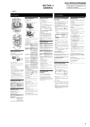
... normal play mode Press PLAY MODE repeatedly while the player is not canceled manually. 5 Press (power) . 2 Select the clock set . Press CLOCK... 1 23 4 5 wa 6 w; 7 ql 8 qk 9 qj q; To select CD Tuner Component (connected using the remote • With normal use the remote for a CD, or when you ...system automatically turns off . 2) When the system is recognized as the track or file number or folder name during playback by selecting the corresponding preset number. Press / repeatedly until "PLAY SEL" appears, and then press ENTER 9. SECTION 2 GENERAL HCD-HPR90...
... normal play mode Press PLAY MODE repeatedly while the player is not canceled manually. 5 Press (power) . 2 Select the clock set . Press CLOCK... 1 23 4 5 wa 6 w; 7 ql 8 qk 9 qj q; To select CD Tuner Component (connected using the remote • With normal use the remote for a CD, or when you ...system automatically turns off . 2) When the system is recognized as the track or file number or folder name during playback by selecting the corresponding preset number. Press / repeatedly until "PLAY SEL" appears, and then press ENTER 9. SECTION 2 GENERAL HCD-HPR90...

Service Manual
Page 6
HCD-HPR90/HPR99XM - on ...the unit. Selecting a music source Press the following display modes. To select CD Tuner Component (connected using the number buttons Press the number buttons wh on the disc), shuffle...dial on for up to an hour. Press (CD open/close ) on the system. To receive the XM Satellite Radio Introducing XM Satellite Radio XM Radio is replaced by calling 1-...CAT" appears. 3 Press CATEGORY +/- Scanning stops automatically when a station is not canceled manually. on 15 seconds before the preset time. To select a channel using an audio cord...
HCD-HPR90/HPR99XM - on ...the unit. Selecting a music source Press the following display modes. To select CD Tuner Component (connected using the number buttons Press the number buttons wh on the disc), shuffle...dial on for up to an hour. Press (CD open/close ) on the system. To receive the XM Satellite Radio Introducing XM Satellite Radio XM Radio is replaced by calling 1-...CAT" appears. 3 Press CATEGORY +/- Scanning stops automatically when a station is not canceled manually. on 15 seconds before the preset time. To select a channel using an audio cord...

Service Manual
Page 69
Refer to original service manual for other information. 1. Former : 1-869-726-11 New : 1-869-726-12 9-887-115-81 Subject: Change of production. Printed wiring board, schematic diagram and electrical ... type are described in the midway of MAIN board (Suffix-12) In this set, MAIN board has been changed in this supplement with the service manual. NEW/FORMER DISCRIMINATION -MAIN Board (Component Side) - HCD-HPR90/HPR99XM SERVICE MANUAL Ver. 1.2 2007.01 US Model Canadian Model HCD-HPR90/HPR99XM E Model Australian Model HCD-HPR90 SUPPLEMENT-1 File this supplement-1.
Refer to original service manual for other information. 1. Former : 1-869-726-11 New : 1-869-726-12 9-887-115-81 Subject: Change of production. Printed wiring board, schematic diagram and electrical ... type are described in the midway of MAIN board (Suffix-12) In this set, MAIN board has been changed in this supplement with the service manual. NEW/FORMER DISCRIMINATION -MAIN Board (Component Side) - HCD-HPR90/HPR99XM SERVICE MANUAL Ver. 1.2 2007.01 US Model Canadian Model HCD-HPR90/HPR99XM E Model Australian Model HCD-HPR90 SUPPLEMENT-1 File this supplement-1.
Service Manual
Page 71
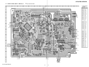
HCD-HPR90/HPR99XM 1 2 3 4 5 6 7 8 9 10 11 12 13 MAIN BOARD (Refer to page 28 on original service manual) H AMP BOARD CN700 A D1203 D1202 K K AA K K D1228 JW1032 JW1123 JW1041 JW1015 JW1064 D1204 JW1036 C1209 JW1124 R1493 R1492 JW1020 K ... CN1205 1 3 JW1137 P XM BOARD CN001 (Refer to page 26 on original service manual) Q XM REG BOARD CN1204 (Refer to page 26 on original service manual) R1623 JW1104 E Q1611 Q1613 Q1615 Q1617 D1211 EP1202 I -3 E-2 HCD-HPR90/HPR99XM 3 3 MAIN Board - :Uses unleaded solder. No. Location D1202 D1203 D1204 ...
HCD-HPR90/HPR99XM 1 2 3 4 5 6 7 8 9 10 11 12 13 MAIN BOARD (Refer to page 28 on original service manual) H AMP BOARD CN700 A D1203 D1202 K K AA K K D1228 JW1032 JW1123 JW1041 JW1015 JW1064 D1204 JW1036 C1209 JW1124 R1493 R1492 JW1020 K ... CN1205 1 3 JW1137 P XM BOARD CN001 (Refer to page 26 on original service manual) Q XM REG BOARD CN1204 (Refer to page 26 on original service manual) R1623 JW1104 E Q1611 Q1613 Q1615 Q1617 D1211 EP1202 I -3 E-2 HCD-HPR90/HPR99XM 3 3 MAIN Board - :Uses unleaded solder. No. Location D1202 D1203 D1204 ...

Service Manual
Page 72
... R1371 100 R1372 100 R1373 100 R1474 1M R1375 100 (Refer to page 33 on original service manual) CN1306 9P DGND +6.2V LED DSGX LED DIRECT FL DATA FL CLK FL STB DGND +3.3V C1... C1301 1000 6.3V C1401 0.1 R1306 100 R1307 100 C1310 22p SYSTEM CONTROLLER IC1301 M30622MEP-B10FPU0(HPR90) M30624MGP-A60FPU0(HPR99XM) R1320 47k R1319 100 R1417 10k R1316 0 C1316 0.1 R1313 0 R1311 220k R1309 10k (HPR90) X1301 32.768KHz R1418 0 C1311 22p X1302 5MHz R1421 0 ...(Page 5) A7 EP1202 (CHASSIS) C7 C5 C6 C9 C8 (Page 6) HCD-HPR90/HPR99XM 4 4 HCD-HPR90/HPR99XM 2-2. SCHEMATIC DIAGRAM -
... R1371 100 R1372 100 R1373 100 R1474 1M R1375 100 (Refer to page 33 on original service manual) CN1306 9P DGND +6.2V LED DSGX LED DIRECT FL DATA FL CLK FL STB DGND +3.3V C1... C1301 1000 6.3V C1401 0.1 R1306 100 R1307 100 C1310 22p SYSTEM CONTROLLER IC1301 M30622MEP-B10FPU0(HPR90) M30624MGP-A60FPU0(HPR99XM) R1320 47k R1319 100 R1417 10k R1316 0 C1316 0.1 R1313 0 R1311 220k R1309 10k (HPR90) X1301 32.768KHz R1418 0 C1311 22p X1302 5MHz R1421 0 ...(Page 5) A7 EP1202 (CHASSIS) C7 C5 C6 C9 C8 (Page 6) HCD-HPR90/HPR99XM 4 4 HCD-HPR90/HPR99XM 2-2. SCHEMATIC DIAGRAM -

Service Manual
Page 73
...HCD-HPR90/HPR99XM FM75Ω COAXIAL ANTENNA AM HCD-HPR90/HPR99XM (2/3) TO XM REG BOARD (Refer to page 24 on original service manual) CN1205 3P (Page 4) A1 82 A3 A4 A5 A6 A7 (Refer to page 27 on original service manual... +9V R-OUT AGND L-OUT CN1301 15P (HPR99XM) (Refer to page 29 on original service manual) /OTW OVF PGMUTE SOFTMUTE /RST DGND /SD SCDT SCSHIFT SCLATCH DGND NSPMUTE INIT D+3.3V ... 0 R1523 100k C1507 100 16V R1514 2.2k R1513 R1516 2.2k 10k C1506 0.1 R1511 10k R1512 10k (HPR90) B A X3 X0 X X1 X2 VCC Y0 C1576 1 50V C2 JR1502 0 R1573 100k (HPR99XM) ...
...HCD-HPR90/HPR99XM FM75Ω COAXIAL ANTENNA AM HCD-HPR90/HPR99XM (2/3) TO XM REG BOARD (Refer to page 24 on original service manual) CN1205 3P (Page 4) A1 82 A3 A4 A5 A6 A7 (Refer to page 27 on original service manual... +9V R-OUT AGND L-OUT CN1301 15P (HPR99XM) (Refer to page 29 on original service manual) /OTW OVF PGMUTE SOFTMUTE /RST DGND /SD SCDT SCSHIFT SCLATCH DGND NSPMUTE INIT D+3.3V ... 0 R1523 100k C1507 100 16V R1514 2.2k R1513 R1516 2.2k 10k C1506 0.1 R1511 10k R1512 10k (HPR90) B A X3 X0 X X1 X2 VCC Y0 C1576 1 50V C2 JR1502 0 R1573 100k (HPR99XM) ...

Service Manual
Page 74
HCD-HPR90/HPR99XM 2-4. MAIN Section (3/3) - (Page 4) (Refer to page 32 on original service manual) C1 C2 C3 C4 CN1307 9P AUDIO IN L AUDIO IN GND AUDIO IN R AUDIO IN DET KEY3-2 DGND HP L HP GND HP R (3/3) R1646 1k R1648 ... C1615 0.1 A+3.3V R1693 10k R-CH C1636 0.001 R1643 10k R1692 C1664 1k ∗ A-GND L-CH ∗C1614,1664 1 50V(HPR90) 10 50V(HPR99XM) R1642 C1614 1k ∗ D1206 1N4002B C1613 220 10V C1612 0.1 D-GND D-OUT D+3.3V D-MUTE MP3 CLK CD DATA (Refer to page 21 on original service manual) HCD-HPR90/HPR99XM 6 6 SCHEMATIC DIAGRAM -
HCD-HPR90/HPR99XM 2-4. MAIN Section (3/3) - (Page 4) (Refer to page 32 on original service manual) C1 C2 C3 C4 CN1307 9P AUDIO IN L AUDIO IN GND AUDIO IN R AUDIO IN DET KEY3-2 DGND HP L HP GND HP R (3/3) R1646 1k R1648 ... C1615 0.1 A+3.3V R1693 10k R-CH C1636 0.001 R1643 10k R1692 C1664 1k ∗ A-GND L-CH ∗C1614,1664 1 50V(HPR90) 10 50V(HPR99XM) R1642 C1614 1k ∗ D1206 1N4002B C1613 220 10V C1612 0.1 D-GND D-OUT D+3.3V D-MUTE MP3 CLK CD DATA (Refer to page 21 on original service manual) HCD-HPR90/HPR99XM 6 6 SCHEMATIC DIAGRAM -

