
Operating Instructions
Page 1
... 1DISC (SHUF) Play. total playing time for help. When you can be downloaded free of charge from the speaker cords and the power cord to avoid picking up to select the AUDIO IN function. Selecting a music source Press the following display modes. Scanning stops automatically when a station is displayed. setting the clock - 2-668-124-11(1) Micro HI-FI Component System Operating Instructions GB Owner's Record The model and serial numbers are located on playing multisession discs • If the disc begins with...
... 1DISC (SHUF) Play. total playing time for help. When you can be downloaded free of charge from the speaker cords and the power cord to avoid picking up to select the AUDIO IN function. Selecting a music source Press the following display modes. Scanning stops automatically when a station is displayed. setting the clock - 2-668-124-11(1) Micro HI-FI Component System Operating Instructions GB Owner's Record The model and serial numbers are located on playing multisession discs • If the disc begins with...

Operating Instructions
Page 2
... to rated output. If there is not set the time to stop playing. 6 Select the sound source. speakers): Approx. 180 × 280 × 360 mm Mass (excl. To view program information, such as in Power Saving Mode. Use buttons on the remote repeatedly. Using the Timers The system offers two timer functions. If you have not ended by a qualified service facility. Use buttons on 15 seconds before operating it...
... to rated output. If there is not set the time to stop playing. 6 Select the sound source. speakers): Approx. 180 × 280 × 360 mm Mass (excl. To view program information, such as in Power Saving Mode. Use buttons on the remote repeatedly. Using the Timers The system offers two timer functions. If you have not ended by a qualified service facility. Use buttons on 15 seconds before operating it...

Service Manual
Page 1
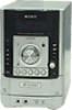
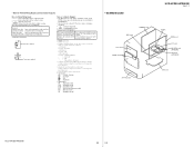
... to rated output. Photo: HCD-HPR90 Model Name Using Similar Mechanism CD Mechanism Name Base Unit Name Optical Pick-Up Block Name NEW DLM5B BU-K6BD83S-WOD KSM-213DCP SPECIFICATIONS Main unit AUDIO POWER SPECIFICATIONS POWER OUTPUT AND TOTAL HARMONIC DISTORION: US model With 4 ohm loads, both channels driven, from Dolby Laboratories. rated 85 watts per channel minimum RMS power, with no more SPEAKER: accepts impedance of 4 ohms CD player section System: Compact disc and digital audio system Laser...
... to rated output. Photo: HCD-HPR90 Model Name Using Similar Mechanism CD Mechanism Name Base Unit Name Optical Pick-Up Block Name NEW DLM5B BU-K6BD83S-WOD KSM-213DCP SPECIFICATIONS Main unit AUDIO POWER SPECIFICATIONS POWER OUTPUT AND TOTAL HARMONIC DISTORION: US model With 4 ohm loads, both channels driven, from Dolby Laboratories. rated 85 watts per channel minimum RMS power, with no more SPEAKER: accepts impedance of 4 ohms CD player section System: Compact disc and digital audio system Laser...

Service Manual
Page 2
...COMPONENTS IDENTIFIED BY MARK 0 OR DOTTED LINE WITH MARK 0 ON THE SCHEMATIC DIAGRAMS AND IN THE PARTS LIST ARE CRITICAL TO SAFE OPERATION. Follow the manufacturers' instructions...SONY. HCD-HPR90/HPR99XM Notes on chip component replacement • Never reuse a disconnected chip component. • Notice that the minus side of a tantalum capacitor may result in hazardous radiation exposure. Using an AC voltmeter to chassis, must have a 2 V AC range are examples of a passive VOM that have an accurate low-voltage scale. A. SAFETY CHECK-OUT After correcting the original service problem...
...COMPONENTS IDENTIFIED BY MARK 0 OR DOTTED LINE WITH MARK 0 ON THE SCHEMATIC DIAGRAMS AND IN THE PARTS LIST ARE CRITICAL TO SAFE OPERATION. Follow the manufacturers' instructions...SONY. HCD-HPR90/HPR99XM Notes on chip component replacement • Never reuse a disconnected chip component. • Notice that the minus side of a tantalum capacitor may result in hazardous radiation exposure. Using an AC voltmeter to chassis, must have a 2 V AC range are examples of a passive VOM that have an accurate low-voltage scale. A. SAFETY CHECK-OUT After correcting the original service problem...
Service Manual
Page 5
... remote repeatedly to adjust the volume. If the current mode appears on the display, press / on using the jog dial. Use the same procedure to select the desired preset number. To select CD Tuner Component (connected using a VBR (variable bit rate). - Playing a CD/MP3 disc 1 Select the CD function. To Pause playback Stop playback Select a folder on . You can be guaranteed. Note on the unit to operate. 1) The STANDBY indicator lights up to set...
... remote repeatedly to adjust the volume. If the current mode appears on the display, press / on using the jog dial. Use the same procedure to select the desired preset number. To select CD Tuner Component (connected using a VBR (variable bit rate). - Playing a CD/MP3 disc 1 Select the CD function. To Pause playback Stop playback Select a folder on . You can be guaranteed. Note on the unit to operate. 1) The STANDBY indicator lights up to set...

Service Manual
Page 6
... priority. Installation costs and other stations. Most XM customers place the antenna in a south-facing window with your favorite radio stations and tune them in the desired channel. Press (power) . 2 Select the clock set the clock. 1 Prepare the sound source. To select CD Tuner Component (connected using the number buttons Press the number buttons wh on the unit) 6 repeatedly. Or turn the jog dial on the remote repeatedly to select a disc. 4 Press / repeatedly or turn the...
... priority. Installation costs and other stations. Most XM customers place the antenna in a south-facing window with your favorite radio stations and tune them in the desired channel. Press (power) . 2 Select the clock set the clock. 1 Prepare the sound source. To select CD Tuner Component (connected using the number buttons Press the number buttons wh on the unit) 6 repeatedly. Or turn the jog dial on the remote repeatedly to select a disc. 4 Press / repeatedly or turn the...
Service Manual
Page 12
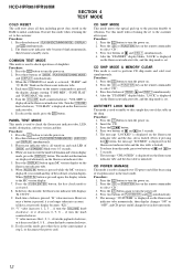
... remote commander to initial conditions. The message "CD POWER" is pressed, the display changes starting "TONE MIN", "TONE FLAT" and "TONE MAX" this mode, press the I /1 button to turn the power on. 2. HCD-HPR90/HPR99XM SECTION 4 TEST MODE COLD RESET The cold reset clears all turned on and each LED of [DSGX], [PLAY MODE/TUNING MODE] and [DISPLAY] simultaneously. 3. Execute this mode when returning the set . Procedure: 1. Press three buttons of [DSGX] and [STANDBY] blink every 0.5 seconds. 4. Turn the [VOLUME...
... remote commander to initial conditions. The message "CD POWER" is pressed, the display changes starting "TONE MIN", "TONE FLAT" and "TONE MAX" this mode, press the I /1 button to turn the power on. 2. HCD-HPR90/HPR99XM SECTION 4 TEST MODE COLD RESET The cold reset clears all turned on and each LED of [DSGX], [PLAY MODE/TUNING MODE] and [DISPLAY] simultaneously. 3. Execute this mode when returning the set . Procedure: 1. Press three buttons of [DSGX] and [STANDBY] blink every 0.5 seconds. 4. Turn the [VOLUME...
Service Manual
Page 14
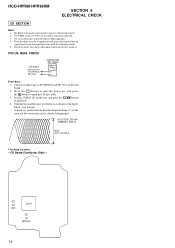
...) 14 CD Block is replaced. Check the focus bias check when optical pick-up block is basically constructed to turn the power on the CD board. 2. VOLT/DIV: 200 mV TIME/DIV: 500 ns level: 0.9 ± 0.4 Vp-p Checking Location: - Connect oscilloscope to TP (RFACI) and TP (VC) on , and press the Z button to playback. 4. Set disc (YEDS-18) on the...
...) 14 CD Block is replaced. Check the focus bias check when optical pick-up block is basically constructed to turn the power on the CD board. 2. VOLT/DIV: 200 mV TIME/DIV: 500 ns level: 0.9 ± 0.4 Vp-p Checking Location: - Connect oscilloscope to TP (RFACI) and TP (VC) on , and press the Z button to playback. 4. Set disc (YEDS-18) on the...
Service Manual
Page 16
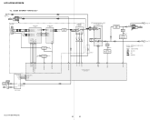
... XM POWER 3.3V XM POWER 5V AUDIO IN DETECT SEL A SEL B SEL INH AMP SI AMP SC LINE MUTE HP MUTE ANTENNA FM 75Ω COAXIAL AM DO/STEREO ST DIN ST CLK ST CE 56 ST DIN/STEREO 54 ST DOUT 55 ST CLK 53 ST CE FM ANT L-OUT R-OUT AM ANT TUNER (FM/AM) R-CH SYSTEM CONTROLLER IC1301 (2/4) HCD-HPR90/HPR99XM...
... XM POWER 3.3V XM POWER 5V AUDIO IN DETECT SEL A SEL B SEL INH AMP SI AMP SC LINE MUTE HP MUTE ANTENNA FM 75Ω COAXIAL AM DO/STEREO ST DIN ST CLK ST CE 56 ST DIN/STEREO 54 ST DOUT 55 ST CLK 53 ST CE FM ANT L-OUT R-OUT AM ANT TUNER (FM/AM) R-CH SYSTEM CONTROLLER IC1301 (2/4) HCD-HPR90/HPR99XM...
Service Manual
Page 18
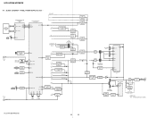
... Q601 D603 T603 SUB POWER TRANSFORMER SHUNT REGULATOR IC650 ISOLATOR PH601 POWER CONTROL IC601 5 DRAIN 4 VCC 2 FB RECT D1 + LINE FILTER T1 F1 (AC IN) + S1 VOLTAGE SELECTOR 120 - 127V 220 - 240V (HPR90: E, E51) Abbrivation E51 : Chilean and Peruvian models HCD-HPR90/HPR99XM 18 18 SEG16 DIN 7 CLK 8 STB 9 GR1 - GR12 1 LED1 B HP (Page 16) REMOTE CONTROL RECEIVER IC951 S951 - 957...
... Q601 D603 T603 SUB POWER TRANSFORMER SHUNT REGULATOR IC650 ISOLATOR PH601 POWER CONTROL IC601 5 DRAIN 4 VCC 2 FB RECT D1 + LINE FILTER T1 F1 (AC IN) + S1 VOLTAGE SELECTOR 120 - 127V 220 - 240V (HPR90: E, E51) Abbrivation E51 : Chilean and Peruvian models HCD-HPR90/HPR99XM 18 18 SEG16 DIN 7 CLK 8 STB 9 GR1 - GR12 1 LED1 B HP (Page 16) REMOTE CONTROL RECEIVER IC951 S951 - 957...
Service Manual
Page 19
... PLAY : XM f : AUDIO IN • Abbreviation AR : Argentina model AUS : Australian model CND : Canadian model E51 : Chilean and Peruvian models MX : Mexican model SP : Singapore model • Circuit Boards Location POWER board AMP board FL board PANEL board HP A-IN board HCD-HPR90/HPR99XM Ver. 1.1 TUNER MAIN board SP board XM REG board (HPR99XM) XM board (HPR99XM) CD board HCD-HPR90/HPR99XM 19 19 Note on Schematic Diagram...
... PLAY : XM f : AUDIO IN • Abbreviation AR : Argentina model AUS : Australian model CND : Canadian model E51 : Chilean and Peruvian models MX : Mexican model SP : Singapore model • Circuit Boards Location POWER board AMP board FL board PANEL board HP A-IN board HCD-HPR90/HPR99XM Ver. 1.1 TUNER MAIN board SP board XM REG board (HPR99XM) XM board (HPR99XM) CD board HCD-HPR90/HPR99XM 19 19 Note on Schematic Diagram...
Service Manual
Page 32
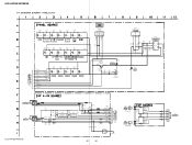
SCHEMATIC DIAGRAM - PANEL Section - TUNING + KEY3-1 (Page 23) 11 KEY3-2 KEY3-1 KEY2 KEY1 VOLUME JOG DGND SIRCS EVER+3.3V LED STANDBY LED DSGX 1 KEY3-1 KEY2 KEY1 VOLUME JOG R975 4.7k S975 DISC 5 R974 2.2k S974 DISC 4 R973 2.2k S973 DISC 3 R972 1k S972 DISC 2 S971 DISC 1 +3.3V GND OUT REMOTE CONTROL RECEIVER IC951 NJL23H400A C955 47 10V Q952 2SA1235 B+ SWITCH D951 SLR325VC STANDBY R947 100 R944 10k R945...
SCHEMATIC DIAGRAM - PANEL Section - TUNING + KEY3-1 (Page 23) 11 KEY3-2 KEY3-1 KEY2 KEY1 VOLUME JOG DGND SIRCS EVER+3.3V LED STANDBY LED DSGX 1 KEY3-1 KEY2 KEY1 VOLUME JOG R975 4.7k S975 DISC 5 R974 2.2k S974 DISC 4 R973 2.2k S973 DISC 3 R972 1k S972 DISC 2 S971 DISC 1 +3.3V GND OUT REMOTE CONTROL RECEIVER IC951 NJL23H400A C955 47 10V Q952 2SA1235 B+ SWITCH D951 SLR325VC STANDBY R947 100 R944 10k R945...
Service Manual
Page 44
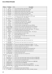
... GFS O Guard frame sync signal output terminal Not used 25 C2PO O C2 pointer signal output terminal Not used 38 MDP O Spindle motor servo control signal output terminal 39 SSTP I CD serial data latch pulse signal input from the system controller "L": reset 9 VSS - Power supply terminal (+1.8V) 36 VSS - Power supply terminal (+1.8V) 18 SVSS - HCD-HPR90/HPR99XM • IC Pin Function Description CD BOARD IC201 CXD3014A-201R (CD DSP) Pin No...
... GFS O Guard frame sync signal output terminal Not used 25 C2PO O C2 pointer signal output terminal Not used 38 MDP O Spindle motor servo control signal output terminal 39 SSTP I CD serial data latch pulse signal input from the system controller "L": reset 9 VSS - Power supply terminal (+1.8V) 36 VSS - Power supply terminal (+1.8V) 18 SVSS - HCD-HPR90/HPR99XM • IC Pin Function Description CD BOARD IC201 CXD3014A-201R (CD DSP) Pin No...
Service Manual
Page 47
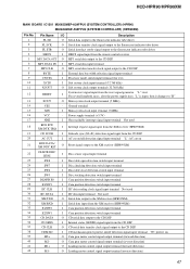
... CD DSP 8 BYTE I External data bus width selection signal input terminal 9 CNVSS I Processor mode switch input terminal (for test) 10 XCIN I Sub system clock input terminal (32.768 kHz) 11 XCOUT O Sub system clock output terminal (32.768 kHz) 12 RESET I CD mechanism power protect on/off detection signal input terminal "L": AC cut on 39 M2+ O Cam gear motor control signal output terminal (forward direction) 40 M2- HCD-HPR90/HPR99XM MAIN BOARD IC1301 M30622MEP-A39FPU0 (SYSTEM CONTROLLER) (HPR90...
... CD DSP 8 BYTE I External data bus width selection signal input terminal 9 CNVSS I Processor mode switch input terminal (for test) 10 XCIN I Sub system clock input terminal (32.768 kHz) 11 XCOUT O Sub system clock output terminal (32.768 kHz) 12 RESET I CD mechanism power protect on/off detection signal input terminal "L": AC cut on 39 M2+ O Cam gear motor control signal output terminal (forward direction) 40 M2- HCD-HPR90/HPR99XM MAIN BOARD IC1301 M30622MEP-A39FPU0 (SYSTEM CONTROLLER) (HPR90...
Service Manual
Page 48
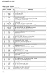
... (HPR99XM) Power on/off control signal output terminal for the XM circuit (HPR99XM) AC power detection signal input terminal Command mode select signal output to the XM receiver (HPR99XM) Serial data input from the EEPROM Serial data transfer clock signal input from the EEPROM LED drive signal output terminal for STANDBY indicator "H": LED on Not used Front panel key input terminal (A/D input) Jog dial pulse input from the rotary encoder (VOLUME) (A/D input) 48 HCD-HPR90/HPR99XM Pin...
... (HPR99XM) Power on/off control signal output terminal for the XM circuit (HPR99XM) AC power detection signal input terminal Command mode select signal output to the XM receiver (HPR99XM) Serial data input from the EEPROM Serial data transfer clock signal input from the EEPROM LED drive signal output terminal for STANDBY indicator "H": LED on Not used Front panel key input terminal (A/D input) Jog dial pulse input from the rotary encoder (VOLUME) (A/D input) 48 HCD-HPR90/HPR99XM Pin...
Service Manual
Page 50
...Serial data output to the system controller Power supply terminal (+3.3V) Serial data input from the system controller Ground terminal Command mode select signal input from the system controller Power supply terminal (+3.3V) Interrupt request signal output to the system controller Ground terminal Reset signal input from the system controller Master/slave mode setting terminal "L": Master mode, "H": Slave mode Fixed at "L" in this set Not used Not used Not used Ground terminal Power supply terminal (+3.3V) XM receiver differential signal (positive) input terminal XM receiver differential signal...
...Serial data output to the system controller Power supply terminal (+3.3V) Serial data input from the system controller Ground terminal Command mode select signal input from the system controller Power supply terminal (+3.3V) Interrupt request signal output to the system controller Ground terminal Reset signal input from the system controller Master/slave mode setting terminal "L": Master mode, "H": Slave mode Fixed at "L" in this set Not used Not used Not used Ground terminal Power supply terminal (+3.3V) XM receiver differential signal (positive) input terminal XM receiver differential signal...
Service Manual
Page 51
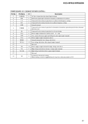
.../frequency setting I Connected to VC1 51 HCD-HPR90/HPR99XM POWER BOARD IC11 CXD9841P (POWER CONTROL) Pin No. 1 2 3 4 5 6 7 8 9 10 11 12 13 14 15 16 17 18 Pin Name VSENSE F/B CT RT GND TIMER SS VC1 OCP VC2 PGND VG (L) VG VS VG (H) - Not used I High voltage side driver reference voltage input terminal O High voltage side driver drive signal output terminal - Not used O Power supply output terminal for driver...
.../frequency setting I Connected to VC1 51 HCD-HPR90/HPR99XM POWER BOARD IC11 CXD9841P (POWER CONTROL) Pin No. 1 2 3 4 5 6 7 8 9 10 11 12 13 14 15 16 17 18 Pin Name VSENSE F/B CT RT GND TIMER SS VC1 OCP VC2 PGND VG (L) VG VS VG (H) - Not used I High voltage side driver reference voltage input terminal O High voltage side driver drive signal output terminal - Not used O Power supply output terminal for driver...

Service Manual
Page 52
...-11 CORD, POWER (HPR90: E51, SP) 1-830-190-11 CORD, POWER (HPR90: US, CND/HPR99XM) 3-703-244-00 BUSHING (2104), CORD (HPR90: US, CND, E51, SP, AR, AUS/HPR99XM) Ref. No. 1 1 2 3 4 5 5 5 5 5 5 07 07 07 07 07 8 1 #2 12 4 Part No. OVERALL SECTION 3 4 not supplied 5 MAIN board The components identified by mark 0 or dotted line with mark 0 are critical for routine service. HCD-HPR90/HPR99XM...
...-11 CORD, POWER (HPR90: E51, SP) 1-830-190-11 CORD, POWER (HPR90: US, CND/HPR99XM) 3-703-244-00 BUSHING (2104), CORD (HPR90: US, CND, E51, SP, AR, AUS/HPR99XM) Ref. No. 1 1 2 3 4 5 5 5 5 5 5 07 07 07 07 07 8 1 #2 12 4 Part No. OVERALL SECTION 3 4 not supplied 5 MAIN board The components identified by mark 0 or dotted line with mark 0 are critical for routine service. HCD-HPR90/HPR99XM...

Service Manual
Page 69
Printed wiring board, schematic diagram and electrical parts list of new type are described in the midway of MAIN board (Suffix-12) In this set, MAIN board has been changed in this supplement with the service manual. Subject: Change of production. Refer to original service manual for other information. 1. Former : 1-869-726-11 New : 1-869-726-12 9-887-115-81 HCD-HPR90/HPR99XM SERVICE MANUAL Ver...
Printed wiring board, schematic diagram and electrical parts list of new type are described in the midway of MAIN board (Suffix-12) In this set, MAIN board has been changed in this supplement with the service manual. Subject: Change of production. Refer to original service manual for other information. 1. Former : 1-869-726-11 New : 1-869-726-12 9-887-115-81 HCD-HPR90/HPR99XM SERVICE MANUAL Ver...
Service Manual
Page 70
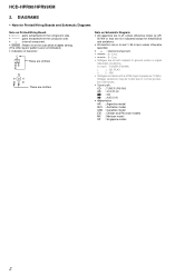
... not indicated.) • Indication of transistor C Q These are taken with respect to normal produc- no -signal (detuned) conditions. F : TUNER (FM/AM) J : XCD PLAY : XM f : AUDIO IN • Abbreviation AR : Argentina model AUS : Australian model CND : Canadian model E51 : Chilean and Peruvian models MX : Mexican model SP : Singapore model 2 HCD-HPR90/HPR99XM 2. DIAGRAMS • Note for electrolytics and tantalums. • All resistors are omitted.
... not indicated.) • Indication of transistor C Q These are taken with respect to normal produc- no -signal (detuned) conditions. F : TUNER (FM/AM) J : XCD PLAY : XM f : AUDIO IN • Abbreviation AR : Argentina model AUS : Australian model CND : Canadian model E51 : Chilean and Peruvian models MX : Mexican model SP : Singapore model 2 HCD-HPR90/HPR99XM 2. DIAGRAMS • Note for electrolytics and tantalums. • All resistors are omitted.


