
Operating Instructions
Page 17
...system right away. For selecting a language used in the on-screen display, refer to page 68. For selecting the aspect ratio of the TV to be connected, refer to page 67. Getting Started Getting Started Quick Overview This chapter presents a quick overview so you have the following items: • Speakers... (5) • Subwoofer (1) • AM loop antenna (1) • FM wire antenna (1) • Speaker cords (5 m × 4, 15 m × 2) (16 ft. × 4, 49 ft...
...system right away. For selecting a language used in the on-screen display, refer to page 68. For selecting the aspect ratio of the TV to be connected, refer to page 67. Getting Started Getting Started Quick Overview This chapter presents a quick overview so you have the following items: • Speakers... (5) • Subwoofer (1) • AM loop antenna (1) • FM wire antenna (1) • Speaker cords (5 m × 4, 15 m × 2) (16 ft. × 4, 49 ft...

Operating Instructions
Page 20
... connecting all the speakers are touching each speaker cord does not touch another speaker terminal or the bare wire of another speaker terminal. To prevent this happens, check the speaker connection again. If no sound is heard from a speaker other due to avoid excessive output on the front panel display, the speaker may damage the system. Notes • Be...
... connecting all the speakers are touching each speaker cord does not touch another speaker terminal or the bare wire of another speaker terminal. To prevent this happens, check the speaker connection again. If no sound is heard from a speaker other due to avoid excessive output on the front panel display, the speaker may damage the system. Notes • Be...
Operating Instructions
Page 21
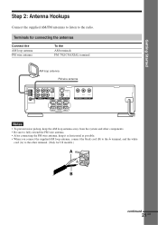
.../CB PR/CR COMPONENT VIDEO OUT REAR R WOOFER REAR L SPEAKER Notes • To prevent noise pickup, keep the AM loop antenna away from the system and other components. • Be sure to fully extend the FM wire antenna. • After connecting the FM wire antenna, keep it as horizontal as possible. • When you...
.../CB PR/CR COMPONENT VIDEO OUT REAR R WOOFER REAR L SPEAKER Notes • To prevent noise pickup, keep the AM loop antenna away from the system and other components. • Be sure to fully extend the FM wire antenna. • After connecting the FM wire antenna, keep it as horizontal as possible. • When you...
Operating Instructions
Page 81
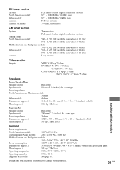
... Antenna terminals PLL quartz-locked digital synthesizer system 87.5 - 108.0 MHz (100 kHz step) 87.5 - 108.0 MHz (50 kHz step) FM wire antenna 75 ohms, unbalanced AM tuner section System Tuner section: PLL quartz-locked digital synthesizer system Tuning range North American model: 530 -...ohms S-VIDEO: Y: 1 Vp-p 75 ohms C: 0.286 Vp-p 75 ohms COMPONENT: Y: 1 Vp-p 75 ohms PB/CB, PR/CR: 0.7 Vp-p 75 ohms Speakers Front/Center/Rear Speaker system Speaker unit Rated impedance Bass reflex 80 mm (3 1/4 inches) dia. cone type 3 ohms 172.5 × 355 × 355 mm (6 7/8 × 14 ×...
... Antenna terminals PLL quartz-locked digital synthesizer system 87.5 - 108.0 MHz (100 kHz step) 87.5 - 108.0 MHz (50 kHz step) FM wire antenna 75 ohms, unbalanced AM tuner section System Tuner section: PLL quartz-locked digital synthesizer system Tuning range North American model: 530 -...ohms S-VIDEO: Y: 1 Vp-p 75 ohms C: 0.286 Vp-p 75 ohms COMPONENT: Y: 1 Vp-p 75 ohms PB/CB, PR/CR: 0.7 Vp-p 75 ohms Speakers Front/Center/Rear Speaker system Speaker unit Rated impedance Bass reflex 80 mm (3 1/4 inches) dia. cone type 3 ohms 172.5 × 355 × 355 mm (6 7/8 × 14 ×...


