
Operating Instructions
Page 5
.... The S-AIR products can be used . For details on the area). The following S-AIR products can enjoy system sound in these Operating Instructions refer only to when the surround amplifier, surround back amplifier, or S-AIR receiver is compatible with the... system: • Surround amplifier: You can enjoy surround speaker sound wirelessly. • Surround back amplifier: You can enjoy surround back speaker sound wirelessly. • S-AIR receiver: You can be purchased as options (the...
.... The S-AIR products can be used . For details on the area). The following S-AIR products can enjoy system sound in these Operating Instructions refer only to when the surround amplifier, surround back amplifier, or S-AIR receiver is compatible with the... system: • Surround amplifier: You can enjoy surround speaker sound wirelessly. • Surround back amplifier: You can enjoy surround back speaker sound wirelessly. • S-AIR receiver: You can be purchased as options (the...

Operating Instructions
Page 6
... Function for "BRAVIA" Sync 63 Calibrating the Appropriate Settings Automatically 66 Setting the Speakers 67 Controlling Your TV with the Supplied Remote 69 Using the Sleep Timer 71 ... Update 75 [Video Settings 76 [Audio Settings 78 [BD/DVD Viewing Settings 80 [Photo Settings 82 [HDMI Settings 82 [System Settings 83 [Network Settings 84 [Easy Setup 85 [Resetting ...86 Additional Information Precautions 87 Notes about the Discs 88 Troubleshooting 89 Self-diagnosis Function 95 Playable Discs 96 Supported...
... Function for "BRAVIA" Sync 63 Calibrating the Appropriate Settings Automatically 66 Setting the Speakers 67 Controlling Your TV with the Supplied Remote 69 Using the Sleep Timer 71 ... Update 75 [Video Settings 76 [Audio Settings 78 [BD/DVD Viewing Settings 80 [Photo Settings 82 [HDMI Settings 82 [System Settings 83 [Network Settings 84 [Easy Setup 85 [Resetting ...86 Additional Information Precautions 87 Notes about the Discs 88 Troubleshooting 89 Self-diagnosis Function 95 Playable Discs 96 Supported...

Operating Instructions
Page 7
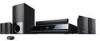
Unpacking BDV-T10 • Front speakers (2) • Surround speakers (2) • Center speaker (1) • FM wire antenna (aerial) (1) • Foot pads (1 set) or • Speaker cords (5, white/red/ blue/gray/green) • Operating Instructions • Speaker and TV Connections guide • Setup Disc (DVD) • DIGITAL MEDIA PORT adapter (TDM-iP20) (1) • Video cord (1) • Subwoofer (1) • Remote commander...
Unpacking BDV-T10 • Front speakers (2) • Surround speakers (2) • Center speaker (1) • FM wire antenna (aerial) (1) • Foot pads (1 set) or • Speaker cords (5, white/red/ blue/gray/green) • Operating Instructions • Speaker and TV Connections guide • Setup Disc (DVD) • DIGITAL MEDIA PORT adapter (TDM-iP20) (1) • Video cord (1) • Subwoofer (1) • Remote commander...
Operating Instructions
Page 8
...; FM wire antenna (aerial) (1) • Foot pads (1 set) or • Speaker cords (5, white/red/ blue/gray/green) • Operating Instructions • Speaker and TV Connections guide • Setup Disc (DVD) • DIGITAL MEDIA PORT adapter (TDM-iP20) (1) • Video cord (1) • Subwoofer (1) • Remote commander (remote) (1) • R6 (size AA) batteries (2) • Operating Instructions...
...; FM wire antenna (aerial) (1) • Foot pads (1 set) or • Speaker cords (5, white/red/ blue/gray/green) • Operating Instructions • Speaker and TV Connections guide • Setup Disc (DVD) • DIGITAL MEDIA PORT adapter (TDM-iP20) (1) • Video cord (1) • Subwoofer (1) • Remote commander (remote) (1) • R6 (size AA) batteries (2) • Operating Instructions...

Operating Instructions
Page 9
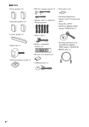
...; Subwoofer (1) • FM wire antenna (aerial) (1) • Foot pads (1 set) or • Speaker cords (6, white/red/ blue/gray/green/purple) • Operating Instructions • Speaker and TV Connections guide • Setup Disc (DVD) • DIGITAL MEDIA PORT adapter (TDM-iP20) (1) • Video cord (1) • Remote commander (remote) (1) • Operating Instructions for the DIGITAL MEDIA...
...; Subwoofer (1) • FM wire antenna (aerial) (1) • Foot pads (1 set) or • Speaker cords (6, white/red/ blue/gray/green/purple) • Operating Instructions • Speaker and TV Connections guide • Setup Disc (DVD) • DIGITAL MEDIA PORT adapter (TDM-iP20) (1) • Video cord (1) • Remote commander (remote) (1) • Operating Instructions for the DIGITAL MEDIA...

Operating Instructions
Page 16
Getting Started Getting Started Step 1: Installing the System Positioning the speakers For the best possible surround sound, place all speakers at the same distance as it may fall down. 16US The subwoofer can be placed anywhere in the room. If you cannot place the center speaker and surround speakers at the same distance from the listening...
Getting Started Getting Started Step 1: Installing the System Positioning the speakers For the best possible surround sound, place all speakers at the same distance as it may fall down. 16US The subwoofer can be placed anywhere in the room. If you cannot place the center speaker and surround speakers at the same distance from the listening...

Operating Instructions
Page 17
Subwoofer Center speaker Front left speaker (L) Front right speaker (R) Surround left speaker (L) Surround right speaker (R) 30 30 45 45 C Surround back left speaker (L) (optional) C Surround back right speaker (R) (optional) 17US Getting Started To add the optional surround back speakers You can enjoy 7.1 surround sound by purchasing the Wireless Surround Speaker Kit (WAHT-SBP1, optional). For the position of the surround back speakers, refer the illustration below (C). The optional product lineup differs depending on the area.
Subwoofer Center speaker Front left speaker (L) Front right speaker (R) Surround left speaker (L) Surround right speaker (R) 30 30 45 45 C Surround back left speaker (L) (optional) C Surround back right speaker (R) (optional) 17US Getting Started To add the optional surround back speakers You can enjoy 7.1 surround sound by purchasing the Wireless Surround Speaker Kit (WAHT-SBP1, optional). For the position of the surround back speakers, refer the illustration below (C). The optional product lineup differs depending on the area.

Operating Instructions
Page 18
... wall strength or improper screw installation, natural calamity, etc. To install the speakers on a wall Before installing the speakers on a wall, connect the speaker cord to the wall. Install the speakers on a vertical and flat wall where reinforcement is applied. • Sony is especially fragile, attach the screws securely to a beam and fasten them to...
... wall strength or improper screw installation, natural calamity, etc. To install the speakers on a wall Before installing the speakers on a wall, connect the speaker cord to the wall. Install the speakers on a vertical and flat wall where reinforcement is applied. • Sony is especially fragile, attach the screws securely to a beam and fasten them to...

Operating Instructions
Page 19
BDV-T10/BDV-T11 For the center speaker 160 mm (6 3/8 inches) BDV-E300 For the center speaker 219 mm (8 5/8 inches) 8 to 10 mm (11/32 to 13/32 inch) For the other speakers 8 to 10 mm (11/32 to 13/32 inch) For the other speakers 8 to 10 mm (11/32 to 13/32 inch) 8 to 10 mm (11/32 to the wall. Getting Started 2 Fasten the screws to 13/32 inch) 3 Hang the speakers on the screws. 5 mm (7/32 inch) 10 mm (13/32 inch) Hole on the back of the speaker Rear of the speaker 19US
BDV-T10/BDV-T11 For the center speaker 160 mm (6 3/8 inches) BDV-E300 For the center speaker 219 mm (8 5/8 inches) 8 to 10 mm (11/32 to 13/32 inch) For the other speakers 8 to 10 mm (11/32 to 13/32 inch) For the other speakers 8 to 10 mm (11/32 to 13/32 inch) 8 to 10 mm (11/32 to the wall. Getting Started 2 Fasten the screws to 13/32 inch) 3 Hang the speakers on the screws. 5 mm (7/32 inch) 10 mm (13/32 inch) Hole on the back of the speaker Rear of the speaker 19US

Operating Instructions
Page 20
... L AM AE.CCMAL-AMCI2C R AUDIO IN Blue (Surround left speaker (L)) Gray (Surround right speaker (R)) To connect speaker cords to match the color of the SPEAKER jacks of the unit. Getting Started Step 2: Connecting the System For connecting the system, read the information on the type of speaker. Note • When you connect another component with the color...
... L AM AE.CCMAL-AMCI2C R AUDIO IN Blue (Surround left speaker (L)) Gray (Surround right speaker (R)) To connect speaker cords to match the color of the SPEAKER jacks of the unit. Getting Started Step 2: Connecting the System For connecting the system, read the information on the type of speaker. Note • When you connect another component with the color...

Operating Instructions
Page 21
... does not have an HDMI jack, but has component video input jacks, connect to using only the video cord connection. Rear panel of the unit SPEAKER CENTER SUBWOOFER B HDMI cable* EZW-T100 COMPONENT VIDEO OUT PR / CR PB / CB Y LAN(1S0PE0A)KER VIDEO OUT HDMI OUT DMPORT D70C05mVA MAX FRONT R FRONT...
... does not have an HDMI jack, but has component video input jacks, connect to using only the video cord connection. Rear panel of the unit SPEAKER CENTER SUBWOOFER B HDMI cable* EZW-T100 COMPONENT VIDEO OUT PR / CR PB / CB Y LAN(1S0PE0A)KER VIDEO OUT HDMI OUT DMPORT D70C05mVA MAX FRONT R FRONT...

Operating Instructions
Page 22
Getting Started Connecting the TV (Audio connection) This connection sends an audio signal to TV sound via the system, perform this connection. Rear panel of the unit SPEAKER CENTER SUBWOOFER EZW-T100 COMPONENT VIDEO OUT PR / CR PB / CB Y LAN(1S0PE0A)KER VIDEO OUT HDMI OUT DMPORT ... optical cord in addition to an audio cord connection. To listen to the unit from the TV. With a digital audio connection, the system receives a Dolby Digital multiplex broadcast signal and you can accept both digital and analog signals. Digital signals have priority over analog signals. If...
Getting Started Connecting the TV (Audio connection) This connection sends an audio signal to TV sound via the system, perform this connection. Rear panel of the unit SPEAKER CENTER SUBWOOFER EZW-T100 COMPONENT VIDEO OUT PR / CR PB / CB Y LAN(1S0PE0A)KER VIDEO OUT HDMI OUT DMPORT ... optical cord in addition to an audio cord connection. To listen to the unit from the TV. With a digital audio connection, the system receives a Dolby Digital multiplex broadcast signal and you can accept both digital and analog signals. Digital signals have priority over analog signals. If...
Operating Instructions
Page 23
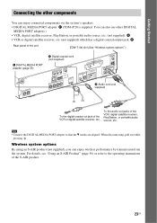
...other components You can enjoy wireless performance by transmission from the system. When disconnecting, pull out while pressing . Wireless system options By using an S-AIR product (not supplied), you can enjoy connected components via the system's speakers. • DIGITAL MEDIA PORT adapter: F (TDM-iP20...supplied) which has a digital coaxial output jack: H Rear panel of the unit EZW-T100 slot (See "Wireless system options".) F DIGITAL MEDIA PORT adapter (page 55) SPEAKER CENTER SUBWOOFER H Digital coaxial cord (not supplied) COMPONENT VIDEO OUT PR / CR PB / CB Y LAN(1S0PE0A)...
...other components You can enjoy wireless performance by transmission from the system. When disconnecting, pull out while pressing . Wireless system options By using an S-AIR product (not supplied), you can enjoy connected components via the system's speakers. • DIGITAL MEDIA PORT adapter: F (TDM-iP20...supplied) which has a digital coaxial output jack: H Rear panel of the unit EZW-T100 slot (See "Wireless system options".) F DIGITAL MEDIA PORT adapter (page 55) SPEAKER CENTER SUBWOOFER H Digital coaxial cord (not supplied) COMPONENT VIDEO OUT PR / CR PB / CB Y LAN(1S0PE0A)...

Operating Instructions
Page 24
Getting Started If your TV has multiple audio/video inputs You can enjoy sound with the speakers of the TV. System VCR, digital satellite receiver, PlayStation, etc. :Signal flow Select the component on the TV. If the TV does not have multiple audio/video inputs, a switcher will be necessary to the operating instructions of the system through the connected TV. TV VCR, digital satellite receiver, PlayStation, etc. Connect the components as follows. For details, refer to receive sound from more than one component. 24US
Getting Started If your TV has multiple audio/video inputs You can enjoy sound with the speakers of the TV. System VCR, digital satellite receiver, PlayStation, etc. :Signal flow Select the component on the TV. If the TV does not have multiple audio/video inputs, a switcher will be necessary to the operating instructions of the system through the connected TV. TV VCR, digital satellite receiver, PlayStation, etc. Connect the components as follows. For details, refer to receive sound from more than one component. 24US

Operating Instructions
Page 26
Rear panel of the unit SPEAKER CENTER SUBWOOFER COMPONENT VIDEO OUT PR / CR PB / CB Y LAN(1S0PE0A)KER VIDEO OUT HDMI OUT ...memory and the unit. • Keep the external memory away from small children to avoid corrupting the external memory data. Sony USM2GL (not supplied) Note • Insert the external memory into the EXT slot as far as it may cause a...8226; Do not apply too much pressure to the external memory in the front panel display when turning the system on the disc (page 43). By connecting an external memory, you force the external memory into the EXT slot. Getting ...
Rear panel of the unit SPEAKER CENTER SUBWOOFER COMPONENT VIDEO OUT PR / CR PB / CB Y LAN(1S0PE0A)KER VIDEO OUT HDMI OUT ...memory and the unit. • Keep the external memory away from small children to avoid corrupting the external memory data. Sony USM2GL (not supplied) Note • Insert the external memory into the EXT slot as far as it may cause a...8226; Do not apply too much pressure to the external memory in the front panel display when turning the system on the disc (page 43). By connecting an external memory, you force the external memory into the EXT slot. Getting ...

Operating Instructions
Page 27
.../ Cable modem (not supplied) Internet Internet To update the system's software using the network See [Network Update] (page 75) and [Software Update Notification] (page 83). SPEAKER CENTER SUBWOOFER COMPONENT VIDEO OUT VIDEO OUT Y PB / CB PR / CR LAN(100) SPEAKER HDMI OUT DMPORT DC5V 700mA MAX FRONT R FRONT L SUR... the unit When connecting to the LAN terminal of the PC. • Depending on the network (LAN) cables, refer to update the system's software using the network. For details on the modem or router, the type of network (LAN) cable, straight or crossing, differs. ...
.../ Cable modem (not supplied) Internet Internet To update the system's software using the network See [Network Update] (page 75) and [Software Update Notification] (page 83). SPEAKER CENTER SUBWOOFER COMPONENT VIDEO OUT VIDEO OUT Y PB / CB PR / CR LAN(100) SPEAKER HDMI OUT DMPORT DC5V 700mA MAX FRONT R FRONT L SUR... the unit When connecting to the LAN terminal of the PC. • Depending on the network (LAN) cables, refer to update the system's software using the network. For details on the modem or router, the type of network (LAN) cable, straight or crossing, differs. ...
Operating Instructions
Page 28
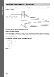
To turn the system on the remote. You can turn off the demonstration simply by pressing "/1 on /off the demonstration mode (Except for U.S. For details, see "About the demonstration" (...). To turn off (standby mode) 123 456 789 "/1 Press "/1. 28US Wall outlet (mains): The shape of the unit to a wall outlet (mains), connect all the speakers to the unit. models) After connecting the AC power cord (mains lead), the demonstration appears in the front panel display. Getting Started Connecting the AC...
To turn the system on the remote. You can turn off the demonstration simply by pressing "/1 on /off the demonstration mode (Except for U.S. For details, see "About the demonstration" (...). To turn off (standby mode) 123 456 789 "/1 Press "/1. 28US Wall outlet (mains): The shape of the unit to a wall outlet (mains), connect all the speakers to the unit. models) After connecting the AC power cord (mains lead), the demonstration appears in the front panel display. Getting Started Connecting the AC...

Operating Instructions
Page 31
...panel. The Setup Display for HDMI] function, select [Off]. 13 Press or c. The front of each speaker should face the calibration mic, and there should be no obstruction between the speakers and the calibration mic. To cancel, select [Cancel]. 31US The Setup Display for [BD Internet Connection] appears... mode. 17 Press or c. Getting Started 12 Press X/x to select the setting for the Control for HDMI] function (page 63) when connecting Sony components that are compatible with a TV connected by HDMI. The default setting is [Normal]. If you do not use the [Control for HDMI ...
...panel. The Setup Display for HDMI] function, select [Off]. 13 Press or c. The front of each speaker should face the calibration mic, and there should be no obstruction between the speakers and the calibration mic. To cancel, select [Cancel]. 31US The Setup Display for [BD Internet Connection] appears... mode. 17 Press or c. Getting Started 12 Press X/x to select the setting for the Control for HDMI] function (page 63) when connecting Sony components that are compatible with a TV connected by HDMI. The default setting is [Normal]. If you do not use the [Control for HDMI ...

Operating Instructions
Page 32
... turn the surround amplifier on the rear panel (page 23) The first page shows the distance of speakers. Function "BD/DVD" "TUNER FM"/ "TUNER AM" "TV" "SAT/CABLE" "DMPORT" "AUDIO" Source Disc that is output when [Auto Calibration] starts. Be quiet during the measurement. Tip • You ...23) DIGITAL MEDIA PORT adapter (page 55) Component that is played by pressing the color button (RED). 22 Press . The system adjusts the speaker setting automatically. The home menu appears on the TV screen. Note • Loud test sound is connected to select [Start], then press . The conclusions ...
... turn the surround amplifier on the rear panel (page 23) The first page shows the distance of speakers. Function "BD/DVD" "TUNER FM"/ "TUNER AM" "TV" "SAT/CABLE" "DMPORT" "AUDIO" Source Disc that is output when [Auto Calibration] starts. Be quiet during the measurement. Tip • You ...23) DIGITAL MEDIA PORT adapter (page 55) Component that is played by pressing the color button (RED). 22 Press . The system adjusts the speaker setting automatically. The home menu appears on the TV screen. Note • Loud test sound is connected to select [Start], then press . The conclusions ...

Operating Instructions
Page 34
...music mode decoding. • Multi-channel source: The system outputs sound from the 5.1 channel speakers by duplicating 2 channel source sound across each speaker. - "2CH STEREO" The system outputs the sound from the 5.1 channel speakers. - Multi-channel surround formats are downmixed to the ...Dolby Pro Logic II music mode decoding. • Multi-channel source: The system outputs sound from all the speakers to the unit. Sound from the 7.1 channel speakers by duplicating 2 channel source sound across each speaker. - "PLII MOVIE" performs Dolby Pro Logic II movie mode decoding. ...
...music mode decoding. • Multi-channel source: The system outputs sound from the 5.1 channel speakers by duplicating 2 channel source sound across each speaker. - "2CH STEREO" The system outputs the sound from the 5.1 channel speakers. - Multi-channel surround formats are downmixed to the ...Dolby Pro Logic II music mode decoding. • Multi-channel source: The system outputs sound from all the speakers to the unit. Sound from the 7.1 channel speakers by duplicating 2 channel source sound across each speaker. - "PLII MOVIE" performs Dolby Pro Logic II movie mode decoding. ...


