
Operating Instructions
Page 6
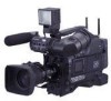
... models depending on the product configuration, as shown in all cases. DSR-400K/400PK DSR-400L/400PL, DSR-450WSL/450WSPL DXF-801 Viewfinder * Microphone VCT-U14 Tripod Adaptor Shoulder strap Test chart for flange focal length adjustment VCL-917BY Zoom Lens DSR-400/400P/450WS/450WSP Camcorder * Part number A-8279-329-A • Lens mount cap • Operating...
... models depending on the product configuration, as shown in all cases. DSR-400K/400PK DSR-400L/400PL, DSR-450WSL/450WSPL DXF-801 Viewfinder * Microphone VCT-U14 Tripod Adaptor Shoulder strap Test chart for flange focal length adjustment VCL-917BY Zoom Lens DSR-400/400P/450WS/450WSP Camcorder * Part number A-8279-329-A • Lens mount cap • Operating...
Operating Instructions
Page 7
...This function automatically traces the white balance, which constantly changes as a scene file in a wide range of the camcorder. Chapter 1 Overview Features The DSR-400/400P DVCAM* digital camcorder is equipped with a 2/3-inch type Power HAD* EX CCD with a "Memory Stick" slot. You can set... 65 dB (DSR-400/450WS), 63 dB (DSR-400P/ 450WSP) The DSR-450WS/450WSP allows you can be copied to make high-angle and low-angle recording easier. Adjustable shoulder pad The camcorder is recorded as ATW, VTR start/stop, etc., to the setting (H/M/L) of Sony Corporation. Loading the...
...This function automatically traces the white balance, which constantly changes as a scene file in a wide range of the camcorder. Chapter 1 Overview Features The DSR-400/400P DVCAM* digital camcorder is equipped with a 2/3-inch type Power HAD* EX CCD with a "Memory Stick" slot. You can set... 65 dB (DSR-400/450WS), 63 dB (DSR-400P/ 450WSP) The DSR-450WS/450WSP allows you can be copied to make high-angle and low-angle recording easier. Adjustable shoulder pad The camcorder is recorded as ATW, VTR start/stop, etc., to the setting (H/M/L) of Sony Corporation. Loading the...

Operating Instructions
Page 15
...locking knob 4 Shoulder strap fitting 5 Viewfinder left -to-right position of the viewfinder (page 30). 15 Location and Function of the REC button on the camcorder or the VTR button on the lens when an external VTR is connected to the (i.LINK) DV OUT connector (page 18). j REC TRIGGER (external ... menu. • Audio recording format Select either Fs48K or 32K. • Audio reference level Select either -12 dB or -20 dB (DSR-400/450WS), -12 dB or -18 dB (DSR-400P/450WSP). • Audio fade-in/fade-out Select either ON or OFF. The audio input is performed locally. FRONT: The microphone...
...locking knob 4 Shoulder strap fitting 5 Viewfinder left -to-right position of the viewfinder (page 30). 15 Location and Function of the REC button on the camcorder or the VTR button on the lens when an external VTR is connected to the (i.LINK) DV OUT connector (page 18). j REC TRIGGER (external ... menu. • Audio recording format Select either Fs48K or 32K. • Audio reference level Select either -12 dB or -20 dB (DSR-400/450WS), -12 dB or -18 dB (DSR-400P/450WSP). • Audio fade-in/fade-out Select either ON or OFF. The audio input is performed locally. FRONT: The microphone...

Operating Instructions
Page 16
... video signal for the following two purposes. • For DSR-400/400P/450WS/450WSP: Inputs a reference signal when the camcorder is to be synchronized with the time code of the camcorder. Blinking: While the cassette is in the camcorder. Non-standard video signals, such as below. DSR-450WS/450WSP only)" on the top of an external...
... video signal for the following two purposes. • For DSR-400/400P/450WS/450WSP: Inputs a reference signal when the camcorder is to be synchronized with the time code of the camcorder. Blinking: While the cassette is in the camcorder. Non-standard video signals, such as below. DSR-450WS/450WSP only)" on the top of an external...

Operating Instructions
Page 20
...in 4:3 mode when connected to match your eyesight (page 30). It operates in the standby-on the camera or camcorder. a Eyepiece focusing knob Adjusts the viewfinder focus to the DSR-400/400P. e LIGHT switch and light The light lights the lens and the switch controls the light as follows. ...In the recording pause state, the camcorder waits for a certain period of Parts HIGH: Brighter LOW: Darker OFF: Turns the light off ...
...in 4:3 mode when connected to match your eyesight (page 30). It operates in the standby-on the camera or camcorder. a Eyepiece focusing knob Adjusts the viewfinder focus to the DSR-400/400P. e LIGHT switch and light The light lights the lens and the switch controls the light as follows. ...In the recording pause state, the camcorder waits for a certain period of Parts HIGH: Brighter LOW: Darker OFF: Turns the light off ...

Operating Instructions
Page 21
... in Interval Rec mode. Flashing quickens while you press the REC button on the camcorder or the VTR button on the lens until recording starts, then stay on the viewfinder screen All items that give details of the status display ... OPERATION menu or with related switches are being changed, during recording. • Indicates a fault (page 125). REC PARA 24 4: 3 EX 3. 2K 16. 0V DC IN DSR-400 05/ 03/23 01:43 SHOT ID(1 - 4) #30001 16: 9 D5600 WHITE NG LEVEL TOO HIGH TCG 00 : 00 : 00 : 00 LOW LIGHT EXT IV DVCAM...
... in Interval Rec mode. Flashing quickens while you press the REC button on the camcorder or the VTR button on the lens until recording starts, then stay on the viewfinder screen All items that give details of the status display ... OPERATION menu or with related switches are being changed, during recording. • Indicates a fault (page 125). REC PARA 24 4: 3 EX 3. 2K 16. 0V DC IN DSR-400 05/ 03/23 01:43 SHOT ID(1 - 4) #30001 16: 9 D5600 WHITE NG LEVEL TOO HIGH TCG 00 : 00 : 00 : 00 LOW LIGHT EXT IV DVCAM...

Operating Instructions
Page 23
...Appears during playback. T: Displayed when ATW is set to DV-SP mode. c Camera scan mode indicator Indicates the camera scan mode of the camcorder when the color bars are displayed, which are displayed. A: Displayed when the WHITE BAL switch is currently playing back or being recorded. r...selected. Chapter 1 Overview q White balance memory Indicates the currently selected white balance automatic adjustment memory. d Non drop-frame mode indicator (DSR-400/450WS only) Appears when non-drop frame mode is locked to an external signal input to PRST or when the preset button on the...
...Appears during playback. T: Displayed when ATW is set to DV-SP mode. c Camera scan mode indicator Indicates the camera scan mode of the camcorder when the color bars are displayed, which are displayed. A: Displayed when the WHITE BAL switch is currently playing back or being recorded. r...selected. Chapter 1 Overview q White balance memory Indicates the currently selected white balance automatic adjustment memory. d Non drop-frame mode indicator (DSR-400/450WS only) Appears when non-drop frame mode is locked to an external signal input to PRST or when the preset button on the...

Operating Instructions
Page 40
... the monitor. See 1) and 2) in the illustration above. Color video monitor DSR-400/400P/450WS/450WSP The items displayed on a monitor are same as the ones... to the SDI IN connector of the color video monitor. Notes • Playing the tape on the camcorder mutes the audio signal portion of the SDI output. • You can connect a color video monitor... to the MONITOR OUT or VIDEO OUT connector of the camcorder. Connections Chapter Chapter 3 Connections Connecting a Monitor As illustrated below, you can select either VBS or SDI ...
... the monitor. See 1) and 2) in the illustration above. Color video monitor DSR-400/400P/450WS/450WSP The items displayed on a monitor are same as the ones... to the SDI IN connector of the color video monitor. Notes • Playing the tape on the camcorder mutes the audio signal portion of the SDI output. • You can connect a color video monitor... to the MONITOR OUT or VIDEO OUT connector of the camcorder. Connections Chapter Chapter 3 Connections Connecting a Monitor As illustrated below, you can select either VBS or SDI ...
Operating Instructions
Page 41
... page of the camcorder using DVCAM or DV format are explained. Also, it records or pauses. For details, see "Usable cassettes" on the external equipment connected to the (i.LINK) DV OUT connector. PARALLEL: Operates both the internal VTR of connection DSR-400/400P/450WS/450WSP External... VTR i.LINK cable (DV cable) DSR-50/PD170, etc. To record the same material using the internal VTR of the camcorder and on the camcorder. If you can be able to the same settings....
... page of the camcorder using DVCAM or DV format are explained. Also, it records or pauses. For details, see "Usable cassettes" on the external equipment connected to the (i.LINK) DV OUT connector. PARALLEL: Operates both the internal VTR of connection DSR-400/400P/450WS/450WSP External... VTR i.LINK cable (DV cable) DSR-50/PD170, etc. To record the same material using the internal VTR of the camcorder and on the camcorder. If you can be able to the same settings....

Operating Instructions
Page 42
... is connected to the camcorder, it is necessary to set to INT ONLY, the i.LINK does not change to stop playback of the external VTR. The i.LINK on the viewfinder and the LCD monitor, and through the MONITOR OUT connector. Example of connection DSR-400/400P/450WS/450WSP External VTR... i.LINK cable (DV cable) DSR-1800A/45, etc. 1 Make the settings below to prepare the external VTR. • Set REC MODE to the same recording mode as a feeder To copy digitally from the camcorder to the VTR without the ...
... is connected to the camcorder, it is necessary to set to INT ONLY, the i.LINK does not change to stop playback of the external VTR. The i.LINK on the viewfinder and the LCD monitor, and through the MONITOR OUT connector. Example of connection DSR-400/400P/450WS/450WSP External VTR... i.LINK cable (DV cable) DSR-1800A/45, etc. 1 Make the settings below to prepare the external VTR. • Set REC MODE to the same recording mode as a feeder To copy digitally from the camcorder to the VTR without the ...
Operating Instructions
Page 43
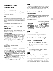
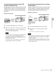
...the external VTR. To control the camcorder from the camcorder. Note To use the automatic copying function of DSR-2000A, it is necessary to set up the non-linear editing software. Example of connection DSR-400/400P/450WS/450WSP External VTR i.LINK cable (DV cable) DSR-2000A, etc. 1 Set the REC... TRIGGER switch to INT ONLY. 2 Make the settings below to be recorded on the VTR MODE page of the camcorder and perform cut editing and digital copy. Example of connection DSR-400/400P/450WS/450WSP PC i.LINK cable (DV cable) Computer with a non-continuous time code may not be used....
...the external VTR. To control the camcorder from the camcorder. Note To use the automatic copying function of DSR-2000A, it is necessary to set up the non-linear editing software. Example of connection DSR-400/400P/450WS/450WSP External VTR i.LINK cable (DV cable) DSR-2000A, etc. 1 Set the REC... TRIGGER switch to INT ONLY. 2 Make the settings below to be recorded on the VTR MODE page of the camcorder and perform cut editing and digital copy. Example of connection DSR-400/400P/450WS/450WSP PC i.LINK cable (DV cable) Computer with a non-continuous time code may not be used....

Operating Instructions
Page 44
... cable BNC cable BNC cable BNC cable to MONITOR/ VIDEO OUT to GENLOCK IN to MONITOR/ VIDEO OUT to this signal. The camcorder will then operate synchronized to GENLOCK IN 44 Other Connections DSR-400/400P/450WS/450WSP DSR-400/400P/450WS/450WSP Camcorder 1 Camcorder 2 * Either the BB (Black Burst) signal or the Color Bar signal, etc.
... cable BNC cable BNC cable BNC cable to MONITOR/ VIDEO OUT to GENLOCK IN to MONITOR/ VIDEO OUT to this signal. The camcorder will then operate synchronized to GENLOCK IN 44 Other Connections DSR-400/400P/450WS/450WSP DSR-400/400P/450WS/450WSP Camcorder 1 Camcorder 2 * Either the BB (Black Burst) signal or the Color Bar signal, etc.
Operating Instructions
Page 52
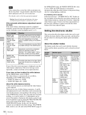
... few times, contact your Sony representative if this message continues to the filter settings. The camcorder has four builtin filters, so a total of eight (4 × 2) adjustments can be completed within the standard number of attempts. Contact your Sony dealer. If the automatic white...shutter This section describes the shutter modes that can be automatically stored in display mode 2 or 3). Shutter mode Standard Shutter speed Application DSR-400/ 450WS DSR400P/ 450WSP Scan Mode: I For shooting 1/100, 1/125, fast-moving 1/250, 1/500, subjects with the electronic ...
... few times, contact your Sony representative if this message continues to the filter settings. The camcorder has four builtin filters, so a total of eight (4 × 2) adjustments can be completed within the standard number of attempts. Contact your Sony dealer. If the automatic white...shutter This section describes the shutter modes that can be automatically stored in display mode 2 or 3). Shutter mode Standard Shutter speed Application DSR-400/ 450WS DSR400P/ 450WSP Scan Mode: I For shooting 1/100, 1/125, fast-moving 1/250, 1/500, subjects with the electronic ...

Operating Instructions
Page 53
...this flicker. • When a bright object is shot in EVS or ECS mode in such a manner that it is retained even when the camcorder is used, the iris opens wider as monitor 50.0 to 6000 Hz screens. EVS (Enhanced Vertical definition System) Shutter speed currently selected in ...shutter speed Use the SHUTTER switch to select a shutter mode or a standard-mode shutter speed. Shutter mode Shutter speed Application ECS (Extended Clear Scan) DSR-400/ 450WS DSR400P/ 450WSP Scan Mode: I For obtaining 60.0 to 6000 Hz images with Scan Mode: PsF no horizontal 30.0 to 7000 Hz bands...
...this flicker. • When a bright object is shot in EVS or ECS mode in such a manner that it is retained even when the camcorder is used, the iris opens wider as monitor 50.0 to 6000 Hz screens. EVS (Enhanced Vertical definition System) Shutter speed currently selected in ...shutter speed Use the SHUTTER switch to select a shutter mode or a standard-mode shutter speed. Shutter mode Shutter speed Application ECS (Extended Clear Scan) DSR-400/ 450WS DSR400P/ 450WSP Scan Mode: I For obtaining 60.0 to 6000 Hz images with Scan Mode: PsF no horizontal 30.0 to 7000 Hz bands...
Operating Instructions
Page 57
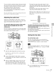
...AUDIO LEVEL AUTO MANUAL AUDIO SELECT 3 2 1 Select the audio channel that you want to DISABLE on . Use a miniscrewdriver to 23:59:59:29 (DSR-400/450WS) or 23:59:59:24 (DSR400P/450WSP) (hours: minutes: seconds: frames). The input level value of the audio channel 2 is the value of... screen. 57 Recording Adjusting the audio level Setting the AUDIO SELECT (CH-1/CH-2) switches to AUTO automatically adjusts the input levels of the camcorder, adjust so that you turn it clockwise, the sensitivity increases, and if you confirm the iris sensitivity after replacing the lens. For details...
...AUDIO LEVEL AUTO MANUAL AUDIO SELECT 3 2 1 Select the audio channel that you want to DISABLE on . Use a miniscrewdriver to 23:59:59:29 (DSR-400/450WS) or 23:59:59:24 (DSR400P/450WSP) (hours: minutes: seconds: frames). The input level value of the audio channel 2 is the value of... screen. 57 Recording Adjusting the audio level Setting the AUDIO SELECT (CH-1/CH-2) switches to AUTO automatically adjusts the input levels of the camcorder, adjust so that you turn it clockwise, the sensitivity increases, and if you confirm the iris sensitivity after replacing the lens. For details...
Operating Instructions
Page 65
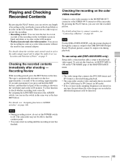
... the recording on the viewfinder screen in black and white or in color on a color video monitor without the need for any length of the camcorder. Chapter 4 Recording and Playback Playing and Checking Recorded Contents By pressing the PLAY button, you can view the recorded picture. There are recorded in ... function, set the POWER switch to ON on the VTR MODE page of the recording (approximately 10 seconds maximum if you can use setup add (DSR-400/450WS only) Setup add is shown in the viewfinder and on the LCD monitor. For details, see the recording in the same way as the...
... the recording on the viewfinder screen in black and white or in color on a color video monitor without the need for any length of the camcorder. Chapter 4 Recording and Playback Playing and Checking Recorded Contents By pressing the PLAY button, you can view the recorded picture. There are recorded in ... function, set the POWER switch to ON on the VTR MODE page of the recording (approximately 10 seconds maximum if you can use setup add (DSR-400/450WS only) Setup add is shown in the viewfinder and on the LCD monitor. For details, see the recording in the same way as the...

Operating Instructions
Page 86
...86 Menu Organization and Operation Sets the validity of the AUDIO LEVEL knob on the front of the camcorder (page 10). (When setting to ENABL, the level of CH-1 is stopped, the camcorder goes to standby-off in and fade-out functions on page 65. Page1 Sets the color temperature of...BEFORE END. Sets the audio reference level. Turns the audio fade-in the event of the camcorder.) - See "To use setup add (DSR-400/ 450WS only)" on or off the function which - Sets the time of the camcorder multiplied by the AUDIO LEVEL (CH-1/CH-2) control on and off . Adjusts the value ...
...86 Menu Organization and Operation Sets the validity of the AUDIO LEVEL knob on the front of the camcorder (page 10). (When setting to ENABL, the level of CH-1 is stopped, the camcorder goes to standby-off in and fade-out functions on page 65. Page1 Sets the color temperature of...BEFORE END. Sets the audio reference level. Turns the audio fade-in the event of the camcorder.) - See "To use setup add (DSR-400/ 450WS only)" on or off the function which - Sets the time of the camcorder multiplied by the AUDIO LEVEL (CH-1/CH-2) control on and off . Adjusts the value ...


