
Service Manual
Page 1
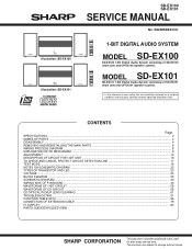
This document has been published to be used . S6248SDEX100/ 1-BIT DIGITAL AUDIO SYSTEM MODEL SD-EX100 SD-EX100 1-Bit Digital Audio System consisting of user-safety the set should be restored to its original ...FL DISPLAY ...84 PARTS GUIDE/EXPLODED VIEW SHARP CORPORATION - 1 - MODEL SD-EX101 SD-EX101 1-Bit Digital Audio System consisting of SD-EX101 (main unit) and CP-EX101 (speaker system). • In the interests of SD-EX100 (main unit) and CP-EX100 (speaker system). Illustration: SD-EX100 Illustration: SD-EX101 SD-EX100 SD-EX101 SERVICE MANUAL No. The contents are subject ...
This document has been published to be used . S6248SDEX100/ 1-BIT DIGITAL AUDIO SYSTEM MODEL SD-EX100 SD-EX100 1-Bit Digital Audio System consisting of user-safety the set should be restored to its original ...FL DISPLAY ...84 PARTS GUIDE/EXPLODED VIEW SHARP CORPORATION - 1 - MODEL SD-EX101 SD-EX101 1-Bit Digital Audio System consisting of SD-EX101 (main unit) and CP-EX101 (speaker system). • In the interests of SD-EX100 (main unit) and CP-EX100 (speaker system). Illustration: SD-EX100 Illustration: SD-EX101 SD-EX100 SD-EX101 SERVICE MANUAL No. The contents are subject ...
Service Manual
Page 2
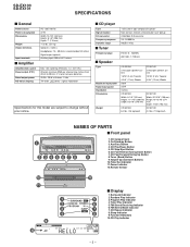
...: 87.5 - 108 MHz AM: 530 - 1,720 kHz CP-EX100 CP-EX101 2-way type speaker sys- 2-way type speaker sys- sigma) modulation Specifications for this model are subject to 20 kHz, 2 % total harmonic distortion 25 W + 25 W at 4 ohms, 1 kHz 7th-order (delta - SD-EX100 SD-EX101 SPECIFICATIONS s General Power source Power consumption Dimensions Weight Output terminals Input...
...: 87.5 - 108 MHz AM: 530 - 1,720 kHz CP-EX100 CP-EX101 2-way type speaker sys- 2-way type speaker sys- sigma) modulation Specifications for this model are subject to 20 kHz, 2 % total harmonic distortion 25 W + 25 W at 4 ohms, 1 kHz 7th-order (delta - SD-EX100 SD-EX101 SPECIFICATIONS s General Power source Power consumption Dimensions Weight Output terminals Input...

Service Manual
Page 3
... 2. Auxiliary Input Jacks 6 4. Headphone Jack 7 6. AM Antenna Ground Terminal 9. Speaker cushion: Attach the cushions to the bottom of the speakers to prevent them from sliding. CD Stop Button 2 12 4. AM Antenna Terminal 9 s Speaker system 1. Cursor/Tuner Preset Buttons 3 13 7. 1 2 (CP-EX100) 2 1 3 34 5 4 5 (CP-EX101) 2 1 3 5 4 SD-EX100 SD-EX101 s Rear panel 1. Tweeter 3. On/Stand-by Button 3. Volume Up...
... 2. Auxiliary Input Jacks 6 4. Headphone Jack 7 6. AM Antenna Ground Terminal 9. Speaker cushion: Attach the cushions to the bottom of the speakers to prevent them from sliding. CD Stop Button 2 12 4. AM Antenna Terminal 9 s Speaker system 1. Cursor/Tuner Preset Buttons 3 13 7. 1 2 (CP-EX100) 2 1 3 34 5 4 5 (CP-EX101) 2 1 3 5 4 SD-EX100 SD-EX101 s Rear panel 1. Tweeter 3. On/Stand-by Button 3. Volume Up...

Service Manual
Page 7
...A1)x1 CP-EX101 STEP REMOVAL 1 Rear Cabinet 2 Tweeter 3 Woofer SD-EX100 SD-EX101 PROCEDURE FIGURE 1. Screw B1) x4 7-4 1. Screw C1) x4 7-4 Net Frame Ass'y Front Panel Rear Cabinet (A2)x1 3 Cloth 2 3 Screw Driver 1 2 Speaker Box (A1)x6 ø3x16mm Tweeter Figure 7-1 (B2)x1 Speaker Box (B2)...Panel (A2)x1 Woofer Woofer Figure 7-2 * (Note 1) The speaker box should not be damaged. - 7 - Net Ass'y A1) x1 7-1 2. Put the speaker on a cloth when disassembling it. 1. Do not remove the inner screws that fix the speaker magnet. Screw Special ..... (B1) x3 7-2 2. Insert the ...
...A1)x1 CP-EX101 STEP REMOVAL 1 Rear Cabinet 2 Tweeter 3 Woofer SD-EX100 SD-EX101 PROCEDURE FIGURE 1. Screw B1) x4 7-4 1. Screw C1) x4 7-4 Net Frame Ass'y Front Panel Rear Cabinet (A2)x1 3 Cloth 2 3 Screw Driver 1 2 Speaker Box (A1)x6 ø3x16mm Tweeter Figure 7-1 (B2)x1 Speaker Box (B2)...Panel (A2)x1 Woofer Woofer Figure 7-2 * (Note 1) The speaker box should not be damaged. - 7 - Net Ass'y A1) x1 7-1 2. Put the speaker on a cloth when disassembling it. 1. Do not remove the inner screws that fix the speaker magnet. Screw Special ..... (B1) x3 7-2 2. Insert the ...

Service Manual
Page 15
...-in auto adjustment of the speaker output terminal (JK400) is stored in the preset memory as shown in Table 1. AC 120V Output Speaker Terminal + UNIT - TEST MODE When the tuner test mode is set, the initial setting of frequencies is within 0±5mV at AC 120V. SD-EX100 SD-EX101 Adjustment for each disc to...
...-in auto adjustment of the speaker output terminal (JK400) is stored in the preset memory as shown in Table 1. AC 120V Output Speaker Terminal + UNIT - TEST MODE When the tuner test mode is set, the initial setting of frequencies is within 0±5mV at AC 120V. SD-EX100 SD-EX101 Adjustment for each disc to...
Service Manual
Page 17
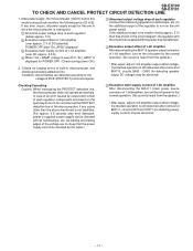
...operation. (No sound is far smaller (below approx. 3 V) 2 Excessive output offset of BIA111, circuits IC570 and IC571 (for detecting speaker output DC voltage) may be abnormal. - 17 - Checking/Cancelling Caution: When interrupting the PROTECT detection line, the microcomputer does not operate...) POWER OFF after removal of 1-bit amplifier), turn on the unit power for POWER OFF. (Check during power ON.) 2. SD-EX100 SD-EX101 TO CHECK AND CANCEL PROTECT CIRCUIT DETECTION LINE 1. If protected operation is still observed after "Err_AP02" displayed 3 Excessive main supply current...
...operation. (No sound is far smaller (below approx. 3 V) 2 Excessive output offset of BIA111, circuits IC570 and IC571 (for detecting speaker output DC voltage) may be abnormal. - 17 - Checking/Cancelling Caution: When interrupting the PROTECT detection line, the microcomputer does not operate...) POWER OFF after removal of 1-bit amplifier), turn on the unit power for POWER OFF. (Check during power ON.) 2. SD-EX100 SD-EX101 TO CHECK AND CANCEL PROTECT CIRCUIT DETECTION LINE 1. If protected operation is still observed after "Err_AP02" displayed 3 Excessive main supply current...
Service Manual
Page 26
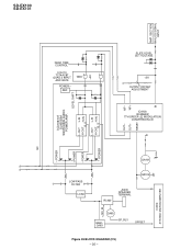
... GATE POWER - S +5V L-OUT L-IN H-OUT H-IN B. POWER - POWER QA101 LOW PASS FILTER LOAD QA102 RL460 JK400 SPEAKER TERMINAL Q465 Q460~ Q463 SP_RLY OFFSET Figure 26 BLOCK DIAGRAM (2/5) - 26 - +12V_M ICD02 SYSTEM MICROCOMPUTER SD-EX100 SD-EX101 AMP. REF GND LEVEL SHIFT L-OUT L-IN H-OUT H-IN B. NF+ SLICE LEVEL SET VOLTAGE +5V OUTPUT OFFSET...
... GATE POWER - S +5V L-OUT L-IN H-OUT H-IN B. POWER - POWER QA101 LOW PASS FILTER LOAD QA102 RL460 JK400 SPEAKER TERMINAL Q465 Q460~ Q463 SP_RLY OFFSET Figure 26 BLOCK DIAGRAM (2/5) - 26 - +12V_M ICD02 SYSTEM MICROCOMPUTER SD-EX100 SD-EX101 AMP. REF GND LEVEL SHIFT L-OUT L-IN H-OUT H-IN B. NF+ SLICE LEVEL SET VOLTAGE +5V OUTPUT OFFSET...

Service Manual
Page 52
... D465 CNW401A 1 CHASSIS GND BK WH PK 3 R485 D482 C417 C486 C414 R486 L481 C487 D481 C485 1 2 3 4 5 6 7 8 9 10 CNP101 R-CH JK400 SPEAKER TERMINAL L-CH WH BK PK WH BK PK 1 2 3 4 5 6 CNS401 P47 10 - G TO DISPLAY PWB CNSD01A CNPD01A C489 R469 R468 CHASSIS GND H CNS707 P50 ... CD SERVO PWB 1 2 3 CNS402 BK P46 6 - B 3 2 1 D425 D423 C423 FROM 1-BIT AMP.PWB D422 C450 C413 C416 T400 FL HEATER P47 9 - SD-EX100 SD-EX101 1 3 A SWITCH B PWB-C3 RD161 SWD12 VOLUME DOWN SWD11 VOLUME UP CNWD02 3 B 1 SWD07 TUNER (BAND) SWD06 CD FAST FORWARD/ TUNING UP RD156 SWD05 CD FAST...
... D465 CNW401A 1 CHASSIS GND BK WH PK 3 R485 D482 C417 C486 C414 R486 L481 C487 D481 C485 1 2 3 4 5 6 7 8 9 10 CNP101 R-CH JK400 SPEAKER TERMINAL L-CH WH BK PK WH BK PK 1 2 3 4 5 6 CNS401 P47 10 - G TO DISPLAY PWB CNSD01A CNPD01A C489 R469 R468 CHASSIS GND H CNS707 P50 ... CD SERVO PWB 1 2 3 CNS402 BK P46 6 - B 3 2 1 D425 D423 C423 FROM 1-BIT AMP.PWB D422 C450 C413 C416 T400 FL HEATER P47 9 - SD-EX100 SD-EX101 1 3 A SWITCH B PWB-C3 RD161 SWD12 VOLUME DOWN SWD11 VOLUME UP CNWD02 3 B 1 SWD07 TUNER (BAND) SWD06 CD FAST FORWARD/ TUNING UP RD156 SWD05 CD FAST...

Service Manual
Page 58
SD-EX100 SD-EX101 WAVEFORMS OF 1-BIT CIRCUIT 2.00 V/div AD IC Output 2.00 V/div + Side 1 2 Amplitude from 0 to imaginary GND of the speaker H-bridge may be monitored. Set value: 20 -25 nsec 2.00 V/div 2.00 V/div 3 2 AD IC NF IN 1 4 500 ns/div 194.545465 µs -12.30 V ...
SD-EX100 SD-EX101 WAVEFORMS OF 1-BIT CIRCUIT 2.00 V/div AD IC Output 2.00 V/div + Side 1 2 Amplitude from 0 to imaginary GND of the speaker H-bridge may be monitored. Set value: 20 -25 nsec 2.00 V/div 2.00 V/div 3 2 AD IC NF IN 1 4 500 ns/div 194.545465 µs -12.30 V ...

Service Manual
Page 75
... detection input from MD unit "H": Normal; Output Port processing. H: Power supply 53 P41/A17 FAN_MOTOR Output Fan motor ON/OFF. Connecting speaker: H 55 P37/A15 MAIN_RLY Output Main power relay control. Connected to MD 45* P51/WRH/BHE - Output Port processing. Fixed at...A10 MECHA_DWN.SW Input CD-mechanism UP SW detection input. (Movable position of CD-mechanism UP/DOWN control motor 58 P34/A12 MECHA_M- SD-EX100 SD-EX101 ICD02 RH-iX0526AWZZ: System Microcomputer (IX0526AW) [To Serial No. 20x04000] (2/3) ICD02 RH-iX0567AWZZ: System Microcomputer (IX0567AW) [From Serial ...
... detection input from MD unit "H": Normal; Output Port processing. H: Power supply 53 P41/A17 FAN_MOTOR Output Fan motor ON/OFF. Connecting speaker: H 55 P37/A15 MAIN_RLY Output Main power relay control. Connected to MD 45* P51/WRH/BHE - Output Port processing. Fixed at...A10 MECHA_DWN.SW Input CD-mechanism UP SW detection input. (Movable position of CD-mechanism UP/DOWN control motor 58 P34/A12 MECHA_M- SD-EX100 SD-EX101 ICD02 RH-iX0526AWZZ: System Microcomputer (IX0526AW) [To Serial No. 20x04000] (2/3) ICD02 RH-iX0567AWZZ: System Microcomputer (IX0567AW) [From Serial ...
Service Manual
Page 85
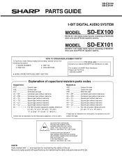
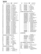
...8A, 125V/ F503 3A, 125V/F504 1.6A, 125V FUSES. "HOW TO ORDER REPLACEMENT PARTS" To have your nearest SHARP Parts Distributor to replace parts with "1" are no indications for maintaining the safety of capacitors/resistors parts codes Capacitors VCC Ceramic...MODEL SD-EX101 SD-EX101 1-Bit Digital Audio System consisting of SD-EX100 (main unit) and CP-EX100 (speaker system). MODEL NUMBER 2. Be sure to order. 3. PARTS GUIDE SD-EX100 SD-EX101 1-BIT DIGITAL AUDIO SYSTEM MODEL SD-EX100 SD-EX100 1-Bit Digital Audio System consisting of SD-EX101 (main unit) and CP-EX101 (speaker system...
...8A, 125V/ F503 3A, 125V/F504 1.6A, 125V FUSES. "HOW TO ORDER REPLACEMENT PARTS" To have your nearest SHARP Parts Distributor to replace parts with "1" are no indications for maintaining the safety of capacitors/resistors parts codes Capacitors VCC Ceramic...MODEL SD-EX101 SD-EX101 1-Bit Digital Audio System consisting of SD-EX100 (main unit) and CP-EX100 (speaker system). MODEL NUMBER 2. Be sure to order. 3. PARTS GUIDE SD-EX100 SD-EX101 1-BIT DIGITAL AUDIO SYSTEM MODEL SD-EX100 SD-EX100 1-Bit Digital Audio System consisting of SD-EX101 (main unit) and CP-EX101 (speaker system...

Service Manual
Page 91
...,Display AF Panel Tape,Top AH Panel Tape,Bottom AC Display Spacer AC Diffusion Sheet,Front AD Diffusion Sheet,Front Top Panel Ass'y [SD-EX100] Top Panel Ass'y [SD-EX101] - NGERR0043AFZZ J MSPRC0961AFZZ J PCUSG0095AWZZ J XBSSD26P06000 J XHBSD20P05000 J XBBSD20P03000 J LX-WZ1070AFZZ J 92LMTR2996CASY J 92LMTR1854BASY J QSW-F9001AW01 J AC Gear,Middle AC Gear,Drive AC ...3Pin AG Core AC Fuse,8A/125V AC Fuse,3A/125V AC Fuse,1.6A/125V AR FM Front End BA FL Display AE Terminal,Speaker AF Jack,Headphones AD Jack,AUX Input AP Motor Ass'y,CD Open/Close AP Motor Ass'y,CD Mechanism Up/ Down AS Motor with ...
...,Display AF Panel Tape,Top AH Panel Tape,Bottom AC Display Spacer AC Diffusion Sheet,Front AD Diffusion Sheet,Front Top Panel Ass'y [SD-EX100] Top Panel Ass'y [SD-EX101] - NGERR0043AFZZ J MSPRC0961AFZZ J PCUSG0095AWZZ J XBSSD26P06000 J XHBSD20P05000 J XBBSD20P03000 J LX-WZ1070AFZZ J 92LMTR2996CASY J 92LMTR1854BASY J QSW-F9001AW01 J AC Gear,Middle AC Gear,Drive AC ...3Pin AG Core AC Fuse,8A/125V AC Fuse,3A/125V AC Fuse,1.6A/125V AR FM Front End BA FL Display AE Terminal,Speaker AF Jack,Headphones AD Jack,AUX Input AP Motor Ass'y,CD Open/Close AP Motor Ass'y,CD Mechanism Up/ Down AS Motor with ...
Service Manual
Page 92
...[SD-EX101] TLABZ0595AWZZ J AB Label,Energy Star 92L6000191001 J Label,Speaker,Left [SD-EX101] 92L6000191011 J Label,Speaker,Right [SD-EX101] 92L8010000101 J Packing Add.,Speaker,Top [SD-EX101] 92L8010000111 J Packing Add.,Speaker,Bottom [SD-EX101] 92L8010000201 J Packing Add.,Speaker,Top [SD-EX100] 92L8010000211 J Packing Add.,Speaker,Bottom [SD-EX100] 92L8100097421 J Sleeve Carton,Speaker [SD-EX101] 92L8100097931 J Sleeve Carton,Speaker [SD-EX100] 92L8100109001 J Pad,Speaker [SD-EX100 Only] 92L8500040061 J Sheet,Speaker [SD-EX101] 92L8500040071 J Sheet,Speaker [SD...
...[SD-EX101] TLABZ0595AWZZ J AB Label,Energy Star 92L6000191001 J Label,Speaker,Left [SD-EX101] 92L6000191011 J Label,Speaker,Right [SD-EX101] 92L8010000101 J Packing Add.,Speaker,Top [SD-EX101] 92L8010000111 J Packing Add.,Speaker,Bottom [SD-EX101] 92L8010000201 J Packing Add.,Speaker,Top [SD-EX100] 92L8010000211 J Packing Add.,Speaker,Bottom [SD-EX100] 92L8100097421 J Sleeve Carton,Speaker [SD-EX101] 92L8100097931 J Sleeve Carton,Speaker [SD-EX100] 92L8100109001 J Pad,Speaker [SD-EX100 Only] 92L8500040061 J Sheet,Speaker [SD-EX101] 92L8500040071 J Sheet,Speaker [SD...

Service Manual
Page 98
... Lid CLOSE SPEAKER SD-EX100 Leg Cushion,Speaker Polyethylene Bag,Speaker 92L8500045401 Packing Add.,Speaker, Top 92L8010000201 Speaker Wire SPEAKER SD-EX101 Polyethylene Bag,Speaker Leg Cushion,Speaker 92L8500045401 Packing Add.,Speaker, Top 92L8010000101 Speaker Wire Pad,Speaker 92L8100109001 Sleeve Carton, Speaker 92L8100097931 FRONT FRONT Packing Add., Speaker, Bottom 92L8010000211 Sheet,Speaker 92L8500040071 Pad,Speaker 92L8100109001 Sleeve Carton, Speaker 92L8100097421 L FRONT FRONT R Label,Speaker, Left 92L6000191001 Sheet,Speaker 92L8500040061 Label,Speaker, Right...
... Lid CLOSE SPEAKER SD-EX100 Leg Cushion,Speaker Polyethylene Bag,Speaker 92L8500045401 Packing Add.,Speaker, Top 92L8010000201 Speaker Wire SPEAKER SD-EX101 Polyethylene Bag,Speaker Leg Cushion,Speaker 92L8500045401 Packing Add.,Speaker, Top 92L8010000101 Speaker Wire Pad,Speaker 92L8100109001 Sleeve Carton, Speaker 92L8100097931 FRONT FRONT Packing Add., Speaker, Bottom 92L8010000211 Sheet,Speaker 92L8500040071 Pad,Speaker 92L8100109001 Sleeve Carton, Speaker 92L8100097421 L FRONT FRONT R Label,Speaker, Left 92L6000191001 Sheet,Speaker 92L8500040061 Label,Speaker, Right...


