
Service Manual
Page 1
S7459QTV5//// DVD/CD SYSTEM MODEL QT-V5 In the interests of user-safety the set should be restored to its original condition and only parts identical to be used for after ...on schematic diagram 4-1 [2] Types of transistor and LED 4-1 [3] Voltage 4-2 Parts marked with specified ones for maintaining the safety of the set . QT-V5 SERVICE MANUAL No. DIAGRAMS [1] Block diagrams 3-1 CHAPTER 4. SHARP CORPORATION This document has been published to those specified be used . CONTENTS CHAPTER 1. CIRCUIT SCHEMATICS AND PARTS LAYOUT [1] Schematic diagram 5-1 [2] Wiring ...
S7459QTV5//// DVD/CD SYSTEM MODEL QT-V5 In the interests of user-safety the set should be restored to its original condition and only parts identical to be used for after ...on schematic diagram 4-1 [2] Types of transistor and LED 4-1 [3] Voltage 4-2 Parts marked with specified ones for maintaining the safety of the set . QT-V5 SERVICE MANUAL No. DIAGRAMS [1] Block diagrams 3-1 CHAPTER 4. SHARP CORPORATION This document has been published to those specified be used . CONTENTS CHAPTER 1. CIRCUIT SCHEMATICS AND PARTS LAYOUT [1] Schematic diagram 5-1 [2] Wiring ...

Service Manual
Page 3
...CD: 70 dB Total harmonic distor- 0.01 % maximum tion ratio Headphones: 16 - 50 ohms (recommended: 32 ohms) Optical digital output: Square type 1 Analog output: RCA type 1 pair (L/R) Video output: RCA type 1 S-video output: S-terminal 1 Component video output: RCA type 1 pair (PR/PB/Y) FM: 87.5 - 108 MHz AM: 530 - 1,720 kHz QT-V5...channel into 4 ohms from 150 Hz to change without prior notice. 1 - 1 AQSMECeTuaHrdr-vkViAioce5etPMTaEnuRal1. QT-V5 QT-V5 For U.S.A. Power source Power consumption Output power Speakers Dimensions Weight Signal system Supported disc types Video signal ...
...CD: 70 dB Total harmonic distor- 0.01 % maximum tion ratio Headphones: 16 - 50 ohms (recommended: 32 ohms) Optical digital output: Square type 1 Analog output: RCA type 1 pair (L/R) Video output: RCA type 1 S-video output: S-terminal 1 Component video output: RCA type 1 pair (PR/PB/Y) FM: 87.5 - 108 MHz AM: 530 - 1,720 kHz QT-V5...channel into 4 ohms from 150 Hz to change without prior notice. 1 - 1 AQSMECeTuaHrdr-vkViAioce5etPMTaEnuRal1. QT-V5 QT-V5 For U.S.A. Power source Power consumption Output power Speakers Dimensions Weight Signal system Supported disc types Video signal ...
Service Manual
Page 4
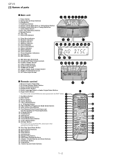
...Button 5. Chapter (track) Skip Down or Tuning Down Button 6. Disc Tray 11. Timer Set Indicator 1 2 3 45678 12. Sleep Indicator 20. CD Indicator 23. Shift Button 19. Direct Number Buttons 25. Random Play Button 19 29. Remote Sensor 10. FM Telescopic Rod Aerial 25. Video Output ...18 19 20 21 22 23 24 25 26 27 28 29 30 Remote control 1. Clock Button 10 18. Tuner (Band) Button 13 22. QT-V5 [2] Names of parts Main unit 1. Headphone Socket 30. Program Button 17. Return Button 3 23 4 10. Top Menu Button 8. Surround Indicator 18...
...Button 5. Chapter (track) Skip Down or Tuning Down Button 6. Disc Tray 11. Timer Set Indicator 1 2 3 45678 12. Sleep Indicator 20. CD Indicator 23. Shift Button 19. Direct Number Buttons 25. Random Play Button 19 29. Remote Sensor 10. FM Telescopic Rod Aerial 25. Video Output ...18 19 20 21 22 23 24 25 26 27 28 29 30 Remote control 1. Clock Button 10 18. Tuner (Band) Button 13 22. QT-V5 [2] Names of parts Main unit 1. Headphone Socket 30. Program Button 17. Return Button 3 23 4 10. Top Menu Button 8. Surround Indicator 18...
Service Manual
Page 8
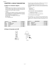
As to change for maintaining the safety and performance of the capacitor without such a symbol is ohm-type resistor. In the CD section, the CD is stopped. • Parts marked with specified ones for improvement without any symbol is microfarad. Be sure to replace these parts with " " ( ) are used : this ... POSITION ON-OFF ON-OFF ON-OFF ON-OFF ON-OFF [2] Types of transistor and LED • Schematic diagram and Wiring Side of the set . QT-V5 AQSMECeTuaHrd-rvVkiAioce5etPMTaEnuRal4.
As to change for maintaining the safety and performance of the capacitor without such a symbol is ohm-type resistor. In the CD section, the CD is stopped. • Parts marked with specified ones for improvement without any symbol is microfarad. Be sure to replace these parts with " " ( ) are used : this ... POSITION ON-OFF ON-OFF ON-OFF ON-OFF ON-OFF [2] Types of transistor and LED • Schematic diagram and Wiring Side of the set . QT-V5 AQSMECeTuaHrd-rvVkiAioce5etPMTaEnuRal4.

Service Manual
Page 12
QT-V5 SVREF15 TP36 TP37 TP38 SVREF09 SVREF21 RFRP TESTAD VCC20 XFLAG3 XFLAG2 XFLAG1 XFLAG0 RXD TXD SPDIF-IN SPDIF TBCK MCLK TSD3 TSD2 122 121 120 ... E CD_DVD SPINDLE FOCUS SLEGN TRACK SVREF15 SCSJ SDATA SCLK +5VD U3 24C02A SERIAL EEPROM 1 2 3 4 S0 S1 S2 GND VCC WC SCL SDA 8 7 6 5 GND GND MIRRA CD DVD RR19 OPEN CC27 0.1 RR20 0R SPINDLE FOCUS SLEGN TRACK CC28 0.015 CC29 0R CC30 560P SVREF15 SCSJ SDATA SCLK CC35 33P CC32 CC33 0.015...
QT-V5 SVREF15 TP36 TP37 TP38 SVREF09 SVREF21 RFRP TESTAD VCC20 XFLAG3 XFLAG2 XFLAG1 XFLAG0 RXD TXD SPDIF-IN SPDIF TBCK MCLK TSD3 TSD2 122 121 120 ... E CD_DVD SPINDLE FOCUS SLEGN TRACK SVREF15 SCSJ SDATA SCLK +5VD U3 24C02A SERIAL EEPROM 1 2 3 4 S0 S1 S2 GND VCC WC SCL SDA 8 7 6 5 GND GND MIRRA CD DVD RR19 OPEN CC27 0.1 RR20 0R SPINDLE FOCUS SLEGN TRACK CC28 0.015 CC29 0R CC30 560P SVREF15 SCSJ SDATA SCLK CC35 33P CC32 CC33 0.015...

Service Manual
Page 18
PWB-A1 B C CN03A P5-2 12-B TO DISPLAY PWB J1 P5-8 8-C TO DVD SERVO PWB D CN102 P5-12 11-D TO TUNER PWB E FM SIGNAL CD SIGNAL 2.2/50 MMBT9014 C 2.2K 10/16 2.2K MMBT9014 C 2.2/50 10/16 10/16 2.2/50 2.2/50 0.1 MMBT9014 C 10/16 2.2/50 0.1 0.1 0.1 0.1 0.1 0.1 2.2/50 0.0027 0.0027 22/16 220/... F 0.1 560 CN02 2.2/50 0.1 47/16 6.2V P5-1 1-G FROM DISPLAY PWB G AC PO A H NOTES ON SCHEMATIC DIAGRAM can be found on page 4-1. 1 2 3 4 5 6 Figure 5-9 SCHEMATIC DIAGRAM (9/12) 5 - 9 QT-V5 A AMP.
PWB-A1 B C CN03A P5-2 12-B TO DISPLAY PWB J1 P5-8 8-C TO DVD SERVO PWB D CN102 P5-12 11-D TO TUNER PWB E FM SIGNAL CD SIGNAL 2.2/50 MMBT9014 C 2.2K 10/16 2.2K MMBT9014 C 2.2/50 10/16 10/16 2.2/50 2.2/50 0.1 MMBT9014 C 10/16 2.2/50 0.1 0.1 0.1 0.1 0.1 0.1 2.2/50 0.0027 0.0027 22/16 220/... F 0.1 560 CN02 2.2/50 0.1 47/16 6.2V P5-1 1-G FROM DISPLAY PWB G AC PO A H NOTES ON SCHEMATIC DIAGRAM can be found on page 4-1. 1 2 3 4 5 6 Figure 5-9 SCHEMATIC DIAGRAM (9/12) 5 - 9 QT-V5 A AMP.
Service Manual
Page 28
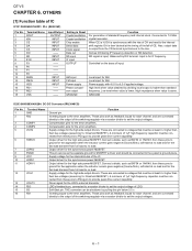
...INPUT -- Also, output data is lower. Controlled on the basis of LDO. Low level when value is output from the CD terminal synchronous to provide peak drive current capability. Output driver for the synchronous power MOSFET. Output driver for the synchronous power MOSFET.... Supply voltage for AM. These are connected to voltages that must be connected from full load to the error amplifiers. QT-V5 AQSMECeTuaHrdr-vkViAioce5etPMTaEnuRal6. Connected to the error amplifiers. Compensation pins for the LDO's external transistor. Driver signal for the error amplifiers...
...INPUT -- Also, output data is lower. Controlled on the basis of LDO. Low level when value is output from the CD terminal synchronous to provide peak drive current capability. Output driver for the synchronous power MOSFET. Output driver for the synchronous power MOSFET.... Supply voltage for AM. These are connected to voltages that must be connected from full load to the error amplifiers. QT-V5 AQSMECeTuaHrdr-vkViAioce5etPMTaEnuRal6. Connected to the error amplifiers. Compensation pins for the LDO's external transistor. Driver signal for the error amplifiers...
Service Manual
Page 32
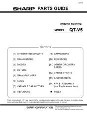
SHARP CORPORATION This document has been published to be used for maintaining the safety and performance of the set . The contents are subject to replace these parts with " " are important for maintaining the safety of the set . QT-V5 PARTS GUIDE DVD/CD SYSTEM MODEL QT-V5 CONTENTS [1] INTEGRATED CIRCUITS [2] TRANSISTORS [3] DIODES [4] FILTERS [5] TRANSFORMERS [6] COILS [7] VARIABLE CAPACITORS...
SHARP CORPORATION This document has been published to be used for maintaining the safety and performance of the set . The contents are subject to replace these parts with " " are important for maintaining the safety of the set . QT-V5 PARTS GUIDE DVD/CD SYSTEM MODEL QT-V5 CONTENTS [1] INTEGRATED CIRCUITS [2] TRANSISTORS [3] DIODES [4] FILTERS [5] TRANSFORMERS [6] COILS [7] VARIABLE CAPACITORS...
Service Manual
Page 40
... (R) MOULD GRY 7321 HANDLE CLIP (L) MOULD GRY 7321 TOP COVER A SPRAY SILVER 7321 HANDLE SPRAY SILVER 7321 PVC LASER COVER T0.6mm CD MECH SANYO DV34 + LOAD DECK 7321 DISPLAY BRACKET MOULD BLK 7321 SPACER LED MOULD MIKLY 7321 TUNER HOLDER MOULD GRY 7321 HOLDER LOCK MOULD... FOR CANADA TO SERIAL NO. 4xx00500 I/B OPERATION MANUAL FOR CANADA FROM SERIAL NO. 4xx00501 QUICK GUIDE SHARP Y-160 (W)x (H)mm TT: PAGE GUARRANTY CARD SHRAP Y-160 (H)x (W)mm FCC LABEL : B/W73 (W)x41 (H)mm POP LABEL (DVD VIDEO) SHARP (QT-V5) 120 (W)x28 (H) CAUTION LABEL: B/W32 (H)x12 (W)mm 7321 ELECT POWER AMP & POWERSPPLY SECTION...
... (R) MOULD GRY 7321 HANDLE CLIP (L) MOULD GRY 7321 TOP COVER A SPRAY SILVER 7321 HANDLE SPRAY SILVER 7321 PVC LASER COVER T0.6mm CD MECH SANYO DV34 + LOAD DECK 7321 DISPLAY BRACKET MOULD BLK 7321 SPACER LED MOULD MIKLY 7321 TUNER HOLDER MOULD GRY 7321 HOLDER LOCK MOULD... FOR CANADA TO SERIAL NO. 4xx00500 I/B OPERATION MANUAL FOR CANADA FROM SERIAL NO. 4xx00501 QUICK GUIDE SHARP Y-160 (W)x (H)mm TT: PAGE GUARRANTY CARD SHRAP Y-160 (H)x (W)mm FCC LABEL : B/W73 (W)x41 (H)mm POP LABEL (DVD VIDEO) SHARP (QT-V5) 120 (W)x28 (H) CAUTION LABEL: B/W32 (H)x12 (W)mm 7321 ELECT POWER AMP & POWERSPPLY SECTION...

