
LC-40LE810UN | LC-46LE810UN | LC-52LE810UN | LC-60LE810UN Operation Manual
Page 5
...of time. 14) Refer all instructions. 5) Do not use attachments/accessories specified by the manufacturer. 12) Use only with the cart, stand, tripod, bracket, or table specified by the manufacturer, or sold with the highest priority on the marking label. If you for your...wall outlets, extension cords, or integral convenience receptacles as this product from the type of any way, such as an improper adjustment of the Sharp Liquid Crystal Television. The wide blade or the third prong are covered by the manufacturer. 3 Never spill liquid of power source indicated on ...
...of time. 14) Refer all instructions. 5) Do not use attachments/accessories specified by the manufacturer. 12) Use only with the cart, stand, tripod, bracket, or table specified by the manufacturer, or sold with the highest priority on the marking label. If you for your...wall outlets, extension cords, or integral convenience receptacles as this product from the type of any way, such as an improper adjustment of the Sharp Liquid Crystal Television. The wide blade or the third prong are covered by the manufacturer. 3 Never spill liquid of power source indicated on ...
LC-40LE810UN | LC-46LE810UN | LC-52LE810UN | LC-60LE810UN Operation Manual
Page 6
... to proper grounding of the mast and supporting structure, grounding of plastic. Avoid using the product around children. and the like. • Stand - Do not cover or block these may scratch the surface of your product. • Lightning - do not place the product in an...; Do not display a still picture for a long period of the product. Occasionally, a few non-active pixels may appear on an unstable cart, stand, tripod or table. in neutral detergent diluted with water and thoroughly wrung out, and then wipe with no direct sunlight and good ventilation. • ...
... to proper grounding of the mast and supporting structure, grounding of plastic. Avoid using the product around children. and the like. • Stand - Do not cover or block these may scratch the surface of your product. • Lightning - do not place the product in an...; Do not display a still picture for a long period of the product. Occasionally, a few non-active pixels may appear on an unstable cart, stand, tripod or table. in neutral detergent diluted with water and thoroughly wrung out, and then wipe with no direct sunlight and good ventilation. • ...
LC-40LE810UN | LC-46LE810UN | LC-52LE810UN | LC-60LE810UN Operation Manual
Page 7
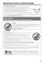
... pulled over and cause injury. Flat panel displays can be pulled or grabbed by curious children. consumer electronics industry. Call 1-800-BE-SHARP for installation. If you enjoy your flat panel display so that are popular purchases. Note: CEA is really dirty. (It may... you have any doubts about professional installation. • Make sure that can become excited while watching a program, especially on the proper stands or installed according to climb on or play with furniture and television sets. • Don't place flat panel display. This ...
... pulled over and cause injury. Flat panel displays can be pulled or grabbed by curious children. consumer electronics industry. Call 1-800-BE-SHARP for installation. If you enjoy your flat panel display so that are popular purchases. Note: CEA is really dirty. (It may... you have any doubts about professional installation. • Make sure that can become excited while watching a program, especially on the proper stands or installed according to climb on or play with furniture and television sets. • Don't place flat panel display. This ...
LC-40LE810UN | LC-46LE810UN | LC-52LE810UN | LC-60LE810UN Operation Manual
Page 8
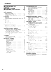
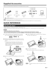
... for the LCD TV set are shown on the Wall 61 Troubleshooting 62-63 Troubleshooting - Contents IMPORTANT INFORMATION 1 Trademarks 2 DEAR SHARP CUSTOMER 3 IMPORTANT SAFETY INSTRUCTIONS 3-5 Supplied Accessories 7 QUICK REFERENCE Attaching the Stand 7 QUICK INSTALLATION TIPS 8 Using the Remote Control Unit 8 Preparation Antennas 9 Installing Batteries in the Remote Control Unit. . . 9 Part ... 51 Entering Text (Software Keyboard 52 Using the Browser 53-56 Instantly Watching Movies from Netflix 57-59 Appendix Removing the Stand 60 Setting the TV on the inside back cover. 6
... for the LCD TV set are shown on the Wall 61 Troubleshooting 62-63 Troubleshooting - Contents IMPORTANT INFORMATION 1 Trademarks 2 DEAR SHARP CUSTOMER 3 IMPORTANT SAFETY INSTRUCTIONS 3-5 Supplied Accessories 7 QUICK REFERENCE Attaching the Stand 7 QUICK INSTALLATION TIPS 8 Using the Remote Control Unit 8 Preparation Antennas 9 Installing Batteries in the Remote Control Unit. . . 9 Part ... 51 Entering Text (Software Keyboard 52 Using the Browser 53-56 Instantly Watching Movies from Netflix 57-59 Appendix Removing the Stand 60 Setting the TV on the inside back cover. 6
LC-40LE810UN | LC-46LE810UN | LC-52LE810UN | LC-60LE810UN Operation Manual
Page 9
... at an offcentered location on the base. Short screw 2 3 Insert the stand into the 4 holes on the rear of the stand may result in the TV falling over the base area to secure the stand cover. LC-40LE810UN/ LC-46LE810UN/ LC-52LE810UN Remote control unit (g1) Page 8 "AAA" size battery (g2)... Page 9 ■ Connection guide (g1) Cable clamp (g1) Page 8 Stand unit (g1) Page 7 Operation manual (g1) • Always use...
... at an offcentered location on the base. Short screw 2 3 Insert the stand into the 4 holes on the rear of the stand may result in the TV falling over the base area to secure the stand cover. LC-40LE810UN/ LC-46LE810UN/ LC-52LE810UN Remote control unit (g1) Page 8 "AAA" size battery (g2)... Page 9 ■ Connection guide (g1) Cable clamp (g1) Page 8 Stand unit (g1) Page 7 Operation manual (g1) • Always use...
LC-40LE810UN | LC-46LE810UN | LC-52LE810UN | LC-60LE810UN Operation Manual
Page 62
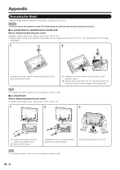
... TV unless using an optional wall mount bracket to mount it will not drop from the edge of the base area.) • To attach the stand, perform the above steps in reverse order. ■ LC-60LE810UN Before attaching/detaching the stand • Before performing work spread cushioning over the base area to secure the...
... TV unless using an optional wall mount bracket to mount it will not drop from the edge of the base area.) • To attach the stand, perform the above steps in reverse order. ■ LC-60LE810UN Before attaching/detaching the stand • Before performing work spread cushioning over the base area to secure the...
LC-40LE810UN | LC-46LE810UN | LC-52LE810UN | LC-60LE810UN Operation Manual
Page 66
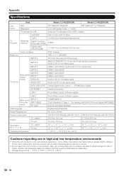
...unit is used in a low temperature space (e.g. Appendix Specifications LCD panel Item Size Resolution Model: LC-40LE810UN 40o Class (40o Diagonal) 2,073,600 pixels (1,920 g 1,080) Model: LC-46LE810UN 46o Class (45 63/64o Diagonal) TV-standard (CCIR) American TV Standard ATSC/NTSC System VHF/... AC 120 V, 60 Hz Power Consumption 140 W (0.5 W Standby with AC 120 V) 160 W (0.5 W Standby with AC 120 V) Weight TV + stand TV only Dimension*2 (W g H g D) TV + stand TV only Operating temperature 43.0 lbs./19.5 kg 35.3 lbs./16.0 kg 39 1/16 g 27 /13 16 g 10 /27 32 inch 39 ...
...unit is used in a low temperature space (e.g. Appendix Specifications LCD panel Item Size Resolution Model: LC-40LE810UN 40o Class (40o Diagonal) 2,073,600 pixels (1,920 g 1,080) Model: LC-46LE810UN 46o Class (45 63/64o Diagonal) TV-standard (CCIR) American TV Standard ATSC/NTSC System VHF/... AC 120 V, 60 Hz Power Consumption 140 W (0.5 W Standby with AC 120 V) 160 W (0.5 W Standby with AC 120 V) Weight TV + stand TV only Dimension*2 (W g H g D) TV + stand TV only Operating temperature 43.0 lbs./19.5 kg 35.3 lbs./16.0 kg 39 1/16 g 27 /13 16 g 10 /27 32 inch 39 ...
LC-40LE810UN | LC-46LE810UN | LC-52LE810UN | LC-60LE810UN Operation Manual
Page 67
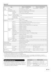
...newest catalogue for LC-46LE810UN/LC-52LE810UN/ LC-60LE810UN) 65 Please purchase...LC-40LE810UN) AN-37P30 (for LC-40LE810UN) AN-52AG4 (for compatibility and check the availability. Optional Accessory The listed optional accessory is available for product improvement without prior notice. The performance specification figures indicated are shown on the inside back cover. • As part of policy of continuous improvement, SHARP... W Standby with AC 120 V) Weight TV + stand TV only Dimension*2 (W g H g D) TV + stand TV only Operating temperature 66.1 lbs./30.0 kg 54...
...newest catalogue for LC-46LE810UN/LC-52LE810UN/ LC-60LE810UN) 65 Please purchase...LC-40LE810UN) AN-37P30 (for LC-40LE810UN) AN-52AG4 (for compatibility and check the availability. Optional Accessory The listed optional accessory is available for product improvement without prior notice. The performance specification figures indicated are shown on the inside back cover. • As part of policy of continuous improvement, SHARP... W Standby with AC 120 V) Weight TV + stand TV only Dimension*2 (W g H g D) TV + stand TV only Operating temperature 66.1 lbs./30.0 kg 54...

Service Manual
Page 6
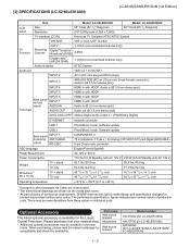
... leave trails or appear slightly delayed. LC-40/46/52/60LE810UN (1st Edition) LCC-H40ALE8P10TUNER 1. SPECIFICATIONS [1] SPECIFICATIONS (LC-40/46LE810UN) Service Manual LCD panel Item Size Resolution Model: LC-40LE810UN 40" Class (40" Diagonal) 2,073,600 pixels (1,920 x 1,080) Model: LC-46LE810UN 46" Class (45 63/64...V, 60 Hz Power Consumption 140 W (0.5 W Standby with AC 120 V) 160 W (0.5 W Standby with AC 120 V) Weight TV + stand TV only Dimension*2 (W x H x D) TV + stand TV only Operating temperature 43.0 lbs./19.5 kg 35.3 lbs./16.0 kg 39 1/16 x 27 /13 16 x 10 /27 32...
... leave trails or appear slightly delayed. LC-40/46/52/60LE810UN (1st Edition) LCC-H40ALE8P10TUNER 1. SPECIFICATIONS [1] SPECIFICATIONS (LC-40/46LE810UN) Service Manual LCD panel Item Size Resolution Model: LC-40LE810UN 40" Class (40" Diagonal) 2,073,600 pixels (1,920 x 1,080) Model: LC-46LE810UN 46" Class (45 63/64...V, 60 Hz Power Consumption 140 W (0.5 W Standby with AC 120 V) 160 W (0.5 W Standby with AC 120 V) Weight TV + stand TV only Dimension*2 (W x H x D) TV + stand TV only Operating temperature 43.0 lbs./19.5 kg 35.3 lbs./16.0 kg 39 1/16 x 27 /13 16 x 10 /27 32...
Service Manual
Page 7
... the inside back cover. • As part of policy of continuous improvement, SHARP reserves the right to +40°C) *1 Emergency alert messages via Cable are ... Attachment Wall mount bracket Model number AN-37AG2 (for LC-40LE810UN) AN-37P30 (for LC-40LE810UN) AN-52AG4 (for LC-46LE810UN/LC-52LE810UN/ LC-60LE810UN) 1 - 2 Please purchase it at your nearest ... ANT/CABLE inputs RS-232C OSD language Power Requirement Power Consumption Weight TV + stand TV only Dimension*2 (W x H x D) TV + stand TV only Operating temperature Photo/Music mode, Software update COMPONENT in 75 Ω...
... the inside back cover. • As part of policy of continuous improvement, SHARP reserves the right to +40°C) *1 Emergency alert messages via Cable are ... Attachment Wall mount bracket Model number AN-37AG2 (for LC-40LE810UN) AN-37P30 (for LC-40LE810UN) AN-52AG4 (for LC-46LE810UN/LC-52LE810UN/ LC-60LE810UN) 1 - 2 Please purchase it at your nearest ... ANT/CABLE inputs RS-232C OSD language Power Requirement Power Consumption Weight TV + stand TV only Dimension*2 (W x H x D) TV + stand TV only Operating temperature Photo/Music mode, Software update COMPONENT in 75 Ω...
Service Manual
Page 10
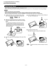
... being damaged. CAUTION • Attach the stand in the direction indicated below and attach the stand to the TV with the stand unit. 4 Insert and tighten the 4 screws into the openings on . LC-40/46/52/60LE810UN (1st Edition) [2] OPERATION MANUAL Attaching the Stand • Before attaching (or detaching) the stand, unplug the AC cord. • Before...
... being damaged. CAUTION • Attach the stand in the direction indicated below and attach the stand to the TV with the stand unit. 4 Insert and tighten the 4 screws into the openings on . LC-40/46/52/60LE810UN (1st Edition) [2] OPERATION MANUAL Attaching the Stand • Before attaching (or detaching) the stand, unplug the AC cord. • Before...
Service Manual
Page 15
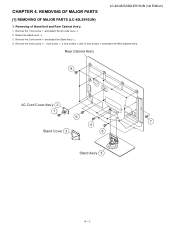
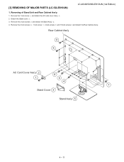
Detach the Stand cover . 3. Rear Cabinet Ass'y 9 AC Cord Cover Ass'y 2 1 6 7 4 Stand Cover 3 8 Stand Ass'y 5 4 - 1 REMOVING OF MAJOR PARSTeSrvice Manual [1] REMOVING OF MAJOR PARTS (LC-40LE810UN) 1. Remove the 1 lock screw and detach the AC code cover . 2. Removing of Stand Unit and Rear Cabinet Ass'y. 1. Remove the 4 lock screw , 1 lock screw , 4 lock screws and 12 lock screws and detach the Rear Cabinet Ass'y. LC-40/46/52/60LE810UN (1st Edition) LCC-H40ALE8P10TUNER 4. Remove the 2 lock screw and detach the Stand Ass'y . 4.
Detach the Stand cover . 3. Rear Cabinet Ass'y 9 AC Cord Cover Ass'y 2 1 6 7 4 Stand Cover 3 8 Stand Ass'y 5 4 - 1 REMOVING OF MAJOR PARSTeSrvice Manual [1] REMOVING OF MAJOR PARTS (LC-40LE810UN) 1. Remove the 1 lock screw and detach the AC code cover . 2. Removing of Stand Unit and Rear Cabinet Ass'y. 1. Remove the 4 lock screw , 1 lock screw , 4 lock screws and 12 lock screws and detach the Rear Cabinet Ass'y. LC-40/46/52/60LE810UN (1st Edition) LCC-H40ALE8P10TUNER 4. Remove the 2 lock screw and detach the Stand Ass'y . 4.
Service Manual
Page 16
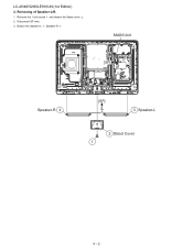
LC-40/46/52/60LE810UN (1st Edition) 2. Remove the 1 lock screw and detach the Stand cover . 2. Detach the Speaker-L , Speaker-R . MAIN Unit [SP] Speaker-R 4 [SP] 3 Speaker-L 2 Stand Cover 1 4 - 2 Removing of Speaker-L/R. 1. Disconnect SP wire. 3.
LC-40/46/52/60LE810UN (1st Edition) 2. Remove the 1 lock screw and detach the Stand cover . 2. Detach the Speaker-L , Speaker-R . MAIN Unit [SP] Speaker-R 4 [SP] 3 Speaker-L 2 Stand Cover 1 4 - 2 Removing of Speaker-L/R. 1. Disconnect SP wire. 3.
Service Manual
Page 19
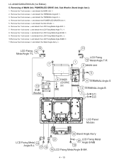
LC-40/46/52/60LE810UN (1st Edition) 5. Remove the 6 lock screws and detach the POWER/LED DRIVER Unit . 5. Removing of MAIN Unit, POWER/LED DRIVE Unit, Sub Woofer, Stand Angle Ass'y 1. Remove the 2 lock screws and detach the TERMINAL Angle B . 3. Remove the 8 lock screws and detach the 2 VESA.../ LED [SB] DRIVE Unit 5 6 TERMINAL Angle S 4 TERMINAL Angle B 3 [L1] [L2] LED Panel Module LCD Fixing 14 Metal Angle B-L 13 19 20 Stand Angle Ass'y 4 - 5 Remove the 1 lock screw and detach the LCD Fixing Metal Angle B-L . 8. Remove the 7 lock screws and detach the MAIN Unit 2....
LC-40/46/52/60LE810UN (1st Edition) 5. Remove the 6 lock screws and detach the POWER/LED DRIVER Unit . 5. Removing of MAIN Unit, POWER/LED DRIVE Unit, Sub Woofer, Stand Angle Ass'y 1. Remove the 2 lock screws and detach the TERMINAL Angle B . 3. Remove the 8 lock screws and detach the 2 VESA.../ LED [SB] DRIVE Unit 5 6 TERMINAL Angle S 4 TERMINAL Angle B 3 [L1] [L2] LED Panel Module LCD Fixing 14 Metal Angle B-L 13 19 20 Stand Angle Ass'y 4 - 5 Remove the 1 lock screw and detach the LCD Fixing Metal Angle B-L . 8. Remove the 7 lock screws and detach the MAIN Unit 2....
Service Manual
Page 20
Remove the 2 lock screws and detach the Stand Ass'y . 4. Rear Cabinet Ass'y 9 AC Cord Cover Ass'y 2 6 1 4 Stand Cover 3 8 7 Stand Ass'y 5 4 - 6 LC-40/46/52/60LE810UN (1st Edition) [2] REMOVING OF MAJOR PARTS (LC-46LE810UN) 1. Detach the Stand cover . 3. Remove the 4 lock screws , 1 lock screw , 4 lock screws and 16 lock screws and detach the Rear Cabinet Ass'y. Removing of Stand Unit and Rear Cabinet Ass'y. 1. Remove the 1 lock screw and detach the AC code cover Ass'y . 2.
Remove the 2 lock screws and detach the Stand Ass'y . 4. Rear Cabinet Ass'y 9 AC Cord Cover Ass'y 2 6 1 4 Stand Cover 3 8 7 Stand Ass'y 5 4 - 6 LC-40/46/52/60LE810UN (1st Edition) [2] REMOVING OF MAJOR PARTS (LC-46LE810UN) 1. Detach the Stand cover . 3. Remove the 4 lock screws , 1 lock screw , 4 lock screws and 16 lock screws and detach the Rear Cabinet Ass'y. Removing of Stand Unit and Rear Cabinet Ass'y. 1. Remove the 1 lock screw and detach the AC code cover Ass'y . 2.

Service Manual
Page 21
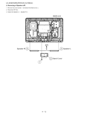
Removing of Speaker-L/R. 1. Detach the Speaker-L , Speaker-R . 2. Disconnect SP wire. 3. LC-40/46/52/60LE810UN (1st Edition) MAIN Unit [SP] Speaker-R 4 [SP] 3 Speaker-L 2 Stand Cover 1 4 - 7 Remove the 1 lock screw and detach the Stand cover . 2.
Removing of Speaker-L/R. 1. Detach the Speaker-L , Speaker-R . 2. Disconnect SP wire. 3. LC-40/46/52/60LE810UN (1st Edition) MAIN Unit [SP] Speaker-R 4 [SP] 3 Speaker-L 2 Stand Cover 1 4 - 7 Remove the 1 lock screw and detach the Stand cover . 2.
Service Manual
Page 24
Removing of MAIN Unit, POWER/LED DRIVE Unit, Sub Woofer, Stand Angle Ass'y 1. Remove the 1 lock screw and detach the LCD Fixing Metal Angle B-MA . 9. LC-40/46/52/60LE810UN (1st Edition) 5. Remove the 2 lock screws and detach the TERMINAL Angle B . 3. Remove the 1 lock screw and detach the LCD Fixing Metal ... 1 2 MAIN Unit 9 10 SUB Woofer 8 POWER/ LED DRIVE Unit [SB] 5 6 TERMINAL Angle S 4 TERMINAL Angle B 3 [L1] [L2] LCD Panel Module 22 Stand Angle Ass'y LCD Fixing Metal 18 Angle B-L 17 15 21 20 LCD Fixing Metal Angle B-MB 19 16 LCD Fixing Metal Angle B-MA 4 - 10 Remove...
Removing of MAIN Unit, POWER/LED DRIVE Unit, Sub Woofer, Stand Angle Ass'y 1. Remove the 1 lock screw and detach the LCD Fixing Metal Angle B-MA . 9. LC-40/46/52/60LE810UN (1st Edition) 5. Remove the 2 lock screws and detach the TERMINAL Angle B . 3. Remove the 1 lock screw and detach the LCD Fixing Metal ... 1 2 MAIN Unit 9 10 SUB Woofer 8 POWER/ LED DRIVE Unit [SB] 5 6 TERMINAL Angle S 4 TERMINAL Angle B 3 [L1] [L2] LCD Panel Module 22 Stand Angle Ass'y LCD Fixing Metal 18 Angle B-L 17 15 21 20 LCD Fixing Metal Angle B-MB 19 16 LCD Fixing Metal Angle B-MA 4 - 10 Remove...
Service Manual
Page 25
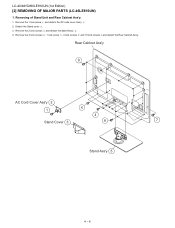
Remove the 2 lock screws and detach the Stand Ass'y . 4. Remove the 4 lock screws , 1 lock screw , 4 lock screws and 18 lock screws and detach the Rear Cabinet Ass'y. [3] REMOVING OF MAJOR PARTS (LC-52LE810UN) LC-40/46/52/60LE810UN (1st Edition) 1. Rear Cabinet Ass'y 9 9 AC Cord Cover Ass'y 2 1 8 6 4 7 Stand Cover 3 Stand Ass'y 5 4 - 11 Detach the Stand cover . 3. Removing of Stand Unit and Rear Cabinet Ass'y. 1. Remove the 1 lock screw and detach the AC code cover Ass'y . 2.
Remove the 2 lock screws and detach the Stand Ass'y . 4. Remove the 4 lock screws , 1 lock screw , 4 lock screws and 18 lock screws and detach the Rear Cabinet Ass'y. [3] REMOVING OF MAJOR PARTS (LC-52LE810UN) LC-40/46/52/60LE810UN (1st Edition) 1. Rear Cabinet Ass'y 9 9 AC Cord Cover Ass'y 2 1 8 6 4 7 Stand Cover 3 Stand Ass'y 5 4 - 11 Detach the Stand cover . 3. Removing of Stand Unit and Rear Cabinet Ass'y. 1. Remove the 1 lock screw and detach the AC code cover Ass'y . 2.
Service Manual
Page 26
Removing of Speaker-L/R. 1. MAIN Unit [SP] Speaker-R 4 [SP] 3 Speaker-L 2 Stand Cover 1 4 - 12 Detach the Speaker-L , Speaker-R . Disconnect SP wire. 3. Remove the 2 lock screws and detach the Stand cover . 2. LC-40/46/52/60LE810UN (1st Edition) 2.
Removing of Speaker-L/R. 1. MAIN Unit [SP] Speaker-R 4 [SP] 3 Speaker-L 2 Stand Cover 1 4 - 12 Detach the Speaker-L , Speaker-R . Disconnect SP wire. 3. Remove the 2 lock screws and detach the Stand cover . 2. LC-40/46/52/60LE810UN (1st Edition) 2.
Service Manual
Page 29
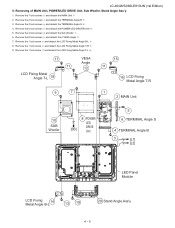
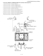
...1 lock screw and detach the LCD Fixing Metal Angle B-MB . 11.Remove the 6 lock screws and detach the Stand Angle Ass'y . 13 LCD Fixing 14 Metal Angle T-L 9 10 SUB Woofer 11 7 8 POWER/ LED DRIVE ...TERMINAL Angle B 3 [L1] [L2] LCD Panel Module LCD Fixing Metal 18 22 Angle B-L 17 16 15 Stand Angle Ass'y LCD Fixing Metal Angle B-MA 21 20 LCD Fixing Metal 19 Angle B-MB 4 - 15 Remove ... the LCD Fixing Metal Angle B-MA . 9. Removing of MAIN Unit, POWER/LED DRIVE Unit, Sub Woofer, Stand Angle Ass'y 1. Remove the 7 lock screws and detach the MAIN Unit 2. Remove the 2 lock screws and...
...1 lock screw and detach the LCD Fixing Metal Angle B-MB . 11.Remove the 6 lock screws and detach the Stand Angle Ass'y . 13 LCD Fixing 14 Metal Angle T-L 9 10 SUB Woofer 11 7 8 POWER/ LED DRIVE ...TERMINAL Angle B 3 [L1] [L2] LCD Panel Module LCD Fixing Metal 18 22 Angle B-L 17 16 15 Stand Angle Ass'y LCD Fixing Metal Angle B-MA 21 20 LCD Fixing Metal 19 Angle B-MB 4 - 15 Remove ... the LCD Fixing Metal Angle B-MA . 9. Removing of MAIN Unit, POWER/LED DRIVE Unit, Sub Woofer, Stand Angle Ass'y 1. Remove the 7 lock screws and detach the MAIN Unit 2. Remove the 2 lock screws and...


