
Service Manual
Page 13
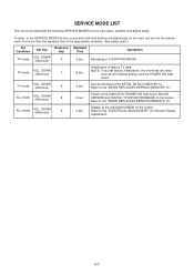
...you can repair, examine and adjust easily. TV mode VOL. Refer to the "WHEN REPLACING EEPROM (MEMORY) IC". DOWN (Minimum) 8 2 sec. Refer to the "WHEN REPLACING EEPROM (MEMORY) IC". DOWN (Minimum) 9 2 sec. Display of the Adjustment MENU on the screen. DOWN (Minimum) 6 2 sec. Initialization ...of MEMORY IC. Can be checked of the INITIAL DATA of factory TV data. Check of V-CHIP PASSWORD. Refer to the SERVICE MODE function, press and hold...
...you can repair, examine and adjust easily. TV mode VOL. Refer to the "WHEN REPLACING EEPROM (MEMORY) IC". DOWN (Minimum) 8 2 sec. Refer to the "WHEN REPLACING EEPROM (MEMORY) IC". DOWN (Minimum) 9 2 sec. Display of the Adjustment MENU on the screen. DOWN (Minimum) 6 2 sec. Initialization ...of MEMORY IC. Can be checked of the INITIAL DATA of factory TV data. Check of V-CHIP PASSWORD. Refer to the SERVICE MODE function, press and hold...
Service Manual
Page 14
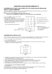
...) IC CONFIRMATION OF CHECK SUM, POWER ON TOTAL HOURS, MICON VERSION AND DIGITAL TV MICON FIRMWARE Initial total of shipping. 10. AD CONVERTER data check sum. Press both VOL. ADDRESS DATA INIT 0000 00 LCD ON 0000 OEC7154B_010 DTV d0l63041 FIG. 2 4. Pressing RIGHT/LEFT button will now have... (6) on the remote control for more than 2 seconds. Press both VOL. Turn on the POWER, and set and Channel button (1) on the screen. Rom correction data check sum. SCALER data check sum. DOWN button on the set to 6 until required DATA value has been selected. 7. The...
...) IC CONFIRMATION OF CHECK SUM, POWER ON TOTAL HOURS, MICON VERSION AND DIGITAL TV MICON FIRMWARE Initial total of shipping. 10. AD CONVERTER data check sum. Press both VOL. ADDRESS DATA INIT 0000 00 LCD ON 0000 OEC7154B_010 DTV d0l63041 FIG. 2 4. Pressing RIGHT/LEFT button will now have... (6) on the remote control for more than 2 seconds. Press both VOL. Turn on the POWER, and set and Channel button (1) on the screen. Rom correction data check sum. SCALER data check sum. DOWN button on the set to 6 until required DATA value has been selected. 7. The...
Service Manual
Page 16
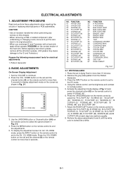
...at each step tone sections equally. 8. Press the VOL. NO. D-1 Set the VOLUME to the AV, CS, HDMI mode. TV 01 H POSI OSD 346 Fig. 2-1 3. To display the adjustment screen for more than 2 seconds to the IC and Transistor). Activate the adjustment mode display of the heat sink. Prepare the following... measurement tools for more than 2 seconds. BASIC ADJUSTMENTS On-Screen Display Adjustment 1. FUNCTION 22 H POSI 60Hz 24 V POSI 60Hz 25 BAK LIGHT CENT 26 BAK LIGHT MAX 27 BAK LIGHT MIN 28 BRIGHT CENT 29 BRIGHT MAX 30 BRIGHT MIN 31 ...
...at each step tone sections equally. 8. Press the VOL. NO. D-1 Set the VOLUME to the AV, CS, HDMI mode. TV 01 H POSI OSD 346 Fig. 2-1 3. To display the adjustment screen for more than 2 seconds to the IC and Transistor). Activate the adjustment mode display of the heat sink. Prepare the following... measurement tools for more than 2 seconds. BASIC ADJUSTMENTS On-Screen Display Adjustment 1. FUNCTION 22 H POSI 60Hz 24 V POSI 60Hz 25 BAK LIGHT CENT 26 BAK LIGHT MAX 27 BAK LIGHT MIN 28 BRIGHT CENT 29 BRIGHT MAX 30 BRIGHT MIN 31 ...
Service Manual
Page 25
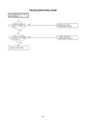
YES CHANGE SCALER PCB. CHECK IC101 AND PERIPHERAL CIRCUIT. YES IS THE COLOR SIGNAL NO AT PINS 57, 58, 59 AND 60 OF IC801 ? E-7 TROUBLESHOOTING GUIDE ON SCREEN DISPLAY DOES NOT APPEAR. IS THERE SIGNAL AT NO PINS 2, 3, 4 AND 5 OF IC101 ? CHECK IC801AND PERIPHERAL CIRCUIT.
YES CHANGE SCALER PCB. CHECK IC101 AND PERIPHERAL CIRCUIT. YES IS THE COLOR SIGNAL NO AT PINS 57, 58, 59 AND 60 OF IC801 ? E-7 TROUBLESHOOTING GUIDE ON SCREEN DISPLAY DOES NOT APPEAR. IS THERE SIGNAL AT NO PINS 2, 3, 4 AND 5 OF IC101 ? CHECK IC801AND PERIPHERAL CIRCUIT.


