
Service Manual
Page 1
...) ...2 SPECIFICATIONS ...3 NAMES OF PARTS ...4 OPERATION MANUAL ...6 QUICK GUIDE (FOR U.S.A. The contents are subject to be used for after sales service only. ONLY) ...8 DISASSEMBLY ...10 REMOVING AND REINSTALLING THE MAIN PARTS 13 ADJUSTMENT ...14 NOTES ON SCHEMATIC DIAGRAM ...18 TYPES OF TRANSISTOR AND LED ...18 BLOCK DIAGRAM ...19 SCHEMATIC DIAGRAM / WIRING SIDE OF P.W.BOARD 22 VOLTAGE ...39 WAVEFORMS OF CD CIRCUIT ...40 TROUBLESHOOTING ...41 FUNCTION TABLE OF IC ...45 FL DISPLAY ...51 REPLACEMENT PARTS LIST...
...) ...2 SPECIFICATIONS ...3 NAMES OF PARTS ...4 OPERATION MANUAL ...6 QUICK GUIDE (FOR U.S.A. The contents are subject to be used for after sales service only. ONLY) ...8 DISASSEMBLY ...10 REMOVING AND REINSTALLING THE MAIN PARTS 13 ADJUSTMENT ...14 NOTES ON SCHEMATIC DIAGRAM ...18 TYPES OF TRANSISTOR AND LED ...18 BLOCK DIAGRAM ...19 SCHEMATIC DIAGRAM / WIRING SIDE OF P.W.BOARD 22 VOLTAGE ...39 WAVEFORMS OF CD CIRCUIT ...40 TROUBLESHOOTING ...41 FUNCTION TABLE OF IC ...45 FL DISPLAY ...51 REPLACEMENT PARTS LIST...

Service Manual
Page 2
... the resistor (See diagram). * Connect the resistor connection to all lead dress to the user, perform the following manner. * Plug the AC line cord directly into a 120 volt AC outlet. * Using two clip leads, connect a 1.5 kohm, 10 watt resistor paralleled by a 0.15 µF capacitor in the audio product. 2. ONLY) BEFORE RETURNING THE AUDIO PRODUCT (Fire & Shock Hazard) Before returning the audio product to make certain that leads...
... the resistor (See diagram). * Connect the resistor connection to all lead dress to the user, perform the following manner. * Plug the AC line cord directly into a 120 volt AC outlet. * Using two clip leads, connect a 1.5 kohm, 10 watt resistor paralleled by a 0.15 µF capacitor in the audio product. 2. ONLY) BEFORE RETURNING THE AUDIO PRODUCT (Fire & Shock Hazard) Before returning the audio product to make certain that leads...
Service Manual
Page 3
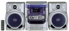
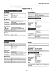
... THE OPERATION MANUAL. SPECIFICATIONS CD-XP300 (Except for Canada)/CD-XP3300 General Power source Power consumption Dimensions Weight AC 120 V, 60 Hz 107 W Width: 10-5/8" (270 mm) Height: 13" (330 mm) Depth: 13-15/16" (355 mm) 17.4 lbs. (7.9 kg) Amplifier Output power Output terminals Input terminals 100 watts minimum RMS per channel into 6 ohms from 60 Hz to 20 kHz, 10% total harmonic distortion Speakers: 6 ohms...
... THE OPERATION MANUAL. SPECIFICATIONS CD-XP300 (Except for Canada)/CD-XP3300 General Power source Power consumption Dimensions Weight AC 120 V, 60 Hz 107 W Width: 10-5/8" (270 mm) Height: 13" (330 mm) Depth: 13-15/16" (355 mm) 17.4 lbs. (7.9 kg) Amplifier Output power Output terminals Input terminals 100 watts minimum RMS per channel into 6 ohms from 60 Hz to 20 kHz, 10% total harmonic distortion Speakers: 6 ohms...
Service Manual
Page 4
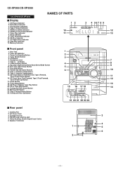
...7 7. Disc Tray Open/Close Button 5 9 11. Tuning and Time Up Button 13 15 16 17 18 14 19 20 21 22 23 24 Rear panel 1. Timer Play Indicator 8. CD Track Up or Fast Forward, Tape 2 Fast Forward, 12 Tuner Preset Up Button 17. Disc Skip Button 12. Tape 2 Cassette Compartment 15. Timer Set Indicator 3. CD Repeat Play Indicator 12. Equalizer Mode Select/Extra Bass/Demo Mode Button 10. Clock Button 18. Cooling Fan 2. Speaker Terminals 3 4 1 5 6 2 - 4 - CD-XP300/CD-XP3300 CD-XP300/CD-XP3300 Display 1. AC Power Cord 3. Transport screw 4. Video/Auxiliary...
...7 7. Disc Tray Open/Close Button 5 9 11. Tuning and Time Up Button 13 15 16 17 18 14 19 20 21 22 23 24 Rear panel 1. Timer Play Indicator 8. CD Track Up or Fast Forward, Tape 2 Fast Forward, 12 Tuner Preset Up Button 17. Disc Skip Button 12. Tape 2 Cassette Compartment 15. Timer Set Indicator 3. CD Repeat Play Indicator 12. Equalizer Mode Select/Extra Bass/Demo Mode Button 10. Clock Button 18. Cooling Fan 2. Speaker Terminals 3 4 1 5 6 2 - 4 - CD-XP300/CD-XP3300 CD-XP300/CD-XP3300 Display 1. AC Power Cord 3. Transport screw 4. Video/Auxiliary...

Service Manual
Page 5
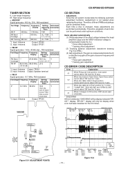
..., Tape Play Button 19. CD-XP300/CD-XP3300 1 12 2 3 13 4 14 5 6 15 7 16 8 17 9 18 10 19 11 20 CP-XP300/CP-XP3300 1. Speaker Wire CP-XP300 1 2 3 3 4 CP-XP3300 1 3 3 2 4 - 5 - Disc Number Select Buttons 4. Equalizer Mode Select Button 14. Tuner Preset Up and Down Buttons 16. Volume Up and Down Buttons Buttons with " " mark in the illustration can be operated on the main unit and the remote control. CD Memory Button 6. Woofer 3. Remote Control Transmitter 2. Tuner (Band) Button 10. Extra Bass Button 13. CD...
..., Tape Play Button 19. CD-XP300/CD-XP3300 1 12 2 3 13 4 14 5 6 15 7 16 8 17 9 18 10 19 11 20 CP-XP300/CP-XP3300 1. Speaker Wire CP-XP300 1 2 3 3 4 CP-XP3300 1 3 3 2 4 - 5 - Disc Number Select Buttons 4. Equalizer Mode Select Button 14. Tuner Preset Up and Down Buttons 16. Volume Up and Down Buttons Buttons with " " mark in the illustration can be operated on the main unit and the remote control. CD Memory Button 6. Woofer 3. Remote Control Transmitter 2. Tuner (Band) Button 10. Extra Bass Button 13. CD...

Service Manual
Page 6
...? Is the FM/AM loop antenna placed properly? Cannot hear treble. Do not open the compartment forcibly. Possible cause Is the AC power cord of the CLOCK button when the AC power supply is flashing, step 3 (for about 1 hour). Are the batteries dead? Does the remote control sensor receive strong light? Hold it has been reset. [Refer to change the time in the unit until electricity resumes...
...? Is the FM/AM loop antenna placed properly? Cannot hear treble. Do not open the compartment forcibly. Possible cause Is the AC power cord of the CLOCK button when the AC power supply is flashing, step 3 (for about 1 hour). Are the batteries dead? Does the remote control sensor receive strong light? Hold it has been reset. [Refer to change the time in the unit until electricity resumes...

Service Manual
Page 7
... previous operation, unplug and plug in memory including clock, timer settings, tuner preset, and CD program. Test of this product is subjected to strong external interference (mechanical shock, excessive static electricity, abnormal supply voltage due to the remote sensor on ? Clearing all the memory by mode and turn on the unit. Make sure that "NO DISC" is displayed. 5 Press the ON/STAND-BY button to close the disc tray. Before...
... previous operation, unplug and plug in memory including clock, timer settings, tuner preset, and CD program. Test of this product is subjected to strong external interference (mechanical shock, excessive static electricity, abnormal supply voltage due to the remote sensor on ? Clearing all the memory by mode and turn on the unit. Make sure that "NO DISC" is displayed. 5 Press the ON/STAND-BY button to close the disc tray. Before...

Service Manual
Page 10
... care on the power supply, .. 10-2 CD Player Unit open the changer manually. (Fig. 10-3) 1. CD-XP300/CD-XP3300 Top Cabinet (A1)x2 ø3x12mm Side Panel (Right) (B1)x2 ø3x10mm Front Panel (A1)x2 ø3x12mm CD-XP300/CD-XP3300 STEP REMOVAL PROCEDURE FIGURE 1 Top Cabinet 1. Screw J1) x1 11-2 10 Turntable 1. Hook M2) x1 3. Figure 10-3 - 10 - Screw B1) x8 10-1 3 CD Tray Cover/ 1. Socket E2...
... care on the power supply, .. 10-2 CD Player Unit open the changer manually. (Fig. 10-3) 1. CD-XP300/CD-XP3300 Top Cabinet (A1)x2 ø3x12mm Side Panel (Right) (B1)x2 ø3x10mm Front Panel (A1)x2 ø3x12mm CD-XP300/CD-XP3300 STEP REMOVAL PROCEDURE FIGURE 1 Top Cabinet 1. Screw J1) x1 11-2 10 Turntable 1. Hook M2) x1 3. Figure 10-3 - 10 - Screw B1) x8 10-1 3 CD Tray Cover/ 1. Socket E2...
Service Manual
Page 15
... kHz 990 kHz (fL): T303 *1 *1. Each time a disc is not needed when replacing the pickup. Input: Antenna Output: TP301 MAIN PWB CD-XP300/CD-XP3300 CD SECTION • Adjustment Since this CD system incorporates the following automatic adjustment functions, readjustment is changed, these adjustments are performed automatically. When tray moves to Open/Close, Open/Close switch cannot detect 'ON' level for 7 secs. 10* When disc table rotate to Disc1 position for...
... kHz 990 kHz (fL): T303 *1 *1. Each time a disc is not needed when replacing the pickup. Input: Antenna Output: TP301 MAIN PWB CD-XP300/CD-XP3300 CD SECTION • Adjustment Since this CD system incorporates the following automatic adjustment functions, readjustment is changed, these adjustments are performed automatically. When tray moves to Open/Close, Open/Close switch cannot detect 'ON' level for 7 secs. 10* When disc table rotate to Disc1 position for...

Service Manual
Page 16
..." = "FGAN_XX" = "RFLS_XX" VOL - key input. key input. IL isn't done buttons make pick's slide possible. OFF To cancel : Power OFF key input. When these following key is using manual. CD-XP300/CD-XP3300 TEST MODE • Setting the test mode Any one of test mode can be appoint directly. CD TEST OPEN/CLOSE operation is input into PLAY key, track number can be in STOP mode. STOP - 16 - key input. for each 2 sec : a) "FOFF_XX...
..." = "FGAN_XX" = "RFLS_XX" VOL - key input. key input. IL isn't done buttons make pick's slide possible. OFF To cancel : Power OFF key input. When these following key is using manual. CD-XP300/CD-XP3300 TEST MODE • Setting the test mode Any one of test mode can be appoint directly. CD TEST OPEN/CLOSE operation is input into PLAY key, track number can be in STOP mode. STOP - 16 - key input. for each 2 sec : a) "FOFF_XX...

Service Manual
Page 17
DISPLAY TIMER LED FLASHING 'ER-TA**' CD/VCD Pickup Mechanism Error. 'ER-CD**' (*) CD Changer Mechanism Error. 'ER-CD**' TUN CD DSP Communication Error Focus Not Match. CD-XP300/CD-XP3300 Standard Specification of 'ER-CD**' display 'ER-CD**' will only be display when CD changer mechanism error had occured, it can be check by pressing 'POWER', 'VIDEO' and 'XBASS' key twice. DC Detection. 00: Tape Mechanism Error. 01: Initial Error. 02: 03: 01: PU-IN SW Detection NG...
DISPLAY TIMER LED FLASHING 'ER-TA**' CD/VCD Pickup Mechanism Error. 'ER-CD**' (*) CD Changer Mechanism Error. 'ER-CD**' TUN CD DSP Communication Error Focus Not Match. CD-XP300/CD-XP3300 Standard Specification of 'ER-CD**' display 'ER-CD**' will only be display when CD changer mechanism error had occured, it can be check by pressing 'POWER', 'VIDEO' and 'XBASS' key twice. DC Detection. 00: Tape Mechanism Error. 01: Initial Error. 02: 03: 01: PU-IN SW Detection NG...

Service Manual
Page 18
... used : the symbol K means 1000 ohm and the symbol M means 1000 kohm and the resistor without such a symbol is the one with no signal given. 1. NO SW714 SW715 SW716 SW717 SW718 SW719 SW720 SW721 SW722 SW723 SW724 SW725 DESCRIPTION VIDEO/AUX TIMER/SLEEP TUNING/TIME UP REC PAUSE MEMORY/SET TUNING/TIME DOWN CLOCK VOLUME UP VOLUME DOWN DISC SKIP OPEN/CLOSE EQUALIZER/X-BASS/DEMO POSITION...
... used : the symbol K means 1000 ohm and the symbol M means 1000 kohm and the resistor without such a symbol is the one with no signal given. 1. NO SW714 SW715 SW716 SW717 SW718 SW719 SW720 SW721 SW722 SW723 SW724 SW725 DESCRIPTION VIDEO/AUX TIMER/SLEEP TUNING/TIME UP REC PAUSE MEMORY/SET TUNING/TIME DOWN CLOCK VOLUME UP VOLUME DOWN DISC SKIP OPEN/CLOSE EQUALIZER/X-BASS/DEMO POSITION...

Service Manual
Page 20
... Q360 FM 7 9 10 3456 17 21 +B5 JK690 VIDEO/AUX L AUX R BI601 1 2 3 SWITCHING +B5 23 L9 DI 1 R 16 CE 2 TAPE TUNER L R L R 10 15 11 14 IC601 CLK LC75341 AUDIO PROCESSOR 24 21 R -20dB ATT Q601 Q602 CD L 12 4L R 13 7 8 1718 3 Q603 Q604 TAPE 1 L-CH P.B. CD-XP300/CD-XP3300 SYSTEM MUTE AM LOOP ANTENNA FM ANTENNA IC301 TA7358AP FM FRONT END FM IF +B6 +B5...
... Q360 FM 7 9 10 3456 17 21 +B5 JK690 VIDEO/AUX L AUX R BI601 1 2 3 SWITCHING +B5 23 L9 DI 1 R 16 CE 2 TAPE TUNER L R L R 10 15 11 14 IC601 CLK LC75341 AUDIO PROCESSOR 24 21 R -20dB ATT Q601 Q602 CD L 12 4L R 13 7 8 1718 3 Q603 Q604 TAPE 1 L-CH P.B. CD-XP300/CD-XP3300 SYSTEM MUTE AM LOOP ANTENNA FM ANTENNA IC301 TA7358AP FM FRONT END FM IF +B6 +B5...

Service Manual
Page 21
... POWER AMP. VOLTAGE REGULATOR F805 5A/125V AC POWER SUPPLY CORD AC 120 V, 60 Hz Figure 21 BLOCK DIAGRAM (3/3) - 21 - L 18 11 L-OUT R 14 7 6 251 8 R-OUT +B1 -B1 +B10 XL700 4.194304 MHz TO CD SECTION RESET Q709 +B10 FAN MOTOR DRIVER Q906 +B7 M4 M FAN MOTOR Q901~ Q904 SP RELAY ON-OFF Q905 RL914 SO901 SPEAKER TERMINAL +B3 D801 PT801 POWER...
... POWER AMP. VOLTAGE REGULATOR F805 5A/125V AC POWER SUPPLY CORD AC 120 V, 60 Hz Figure 21 BLOCK DIAGRAM (3/3) - 21 - L 18 11 L-OUT R 14 7 6 251 8 R-OUT +B1 -B1 +B10 XL700 4.194304 MHz TO CD SECTION RESET Q709 +B10 FAN MOTOR DRIVER Q906 +B7 M4 M FAN MOTOR Q901~ Q904 SP RELAY ON-OFF Q905 RL914 SO901 SPEAKER TERMINAL +B3 D801 PT801 POWER...

Service Manual
Page 41
... product is clean. "E-CD01" is displayed. (1) Check the power to IC1 (LC78645NE), the presence of the clock signal (33.8688 MHz) and the status of the RESET terminal (pin 66 on the CD cleaner disc which has the mark next to the PICKUP-IN Switch (SW4) position? Clean the objective lens, and check the playback operation. Turn the power off any adjustment make...
... product is clean. "E-CD01" is displayed. (1) Check the power to IC1 (LC78645NE), the presence of the clock signal (33.8688 MHz) and the status of the RESET terminal (pin 66 on the CD cleaner disc which has the mark next to the PICKUP-IN Switch (SW4) position? Clean the objective lens, and check the playback operation. Turn the power off any adjustment make...

Service Manual
Page 45
... for focus control. D/A output. 21 FDO Output ADAVDD/2 Output terminal for jitter detection. 18 ADAVDD Input - When not used , connect to 0 V. 29* DEFECT Output L Defect terminal. 30* V/*P Output H Auto switching monitor output terminal for rough servo phase control. "H": rough servo, "L": phase servo. 31* FSEQ Output L Sync signal detection output terminal. Digital system power terminal. 39* DOUT Output L Digital OUT output terminal. (EIAJ format) 40 TEST Input L Input terminal for SLCO output current setting. - Left channel output. In...
... for focus control. D/A output. 21 FDO Output ADAVDD/2 Output terminal for jitter detection. 18 ADAVDD Input - When not used , connect to 0 V. 29* DEFECT Output L Defect terminal. 30* V/*P Output H Auto switching monitor output terminal for rough servo phase control. "H": rough servo, "L": phase servo. 31* FSEQ Output L Sync signal detection output terminal. Digital system power terminal. 39* DOUT Output L Digital OUT output terminal. (EIAJ format) 40 TEST Input L Input terminal for SLCO output current setting. - Left channel output. In...

Service Manual
Page 46
... controlled by connecting to 0 V. CD-XP300/CD-XP3300 IC1 VHiLC78645NE1: CD Servo (LC78645NE) (2/2) Pin No. Power supply for Right channel. Input - PDO output current adjustment resistor connection port. 77 VVDD Input - Be sure to supply the same potential to each power terminal. (VVDD, ADAVDD, VDD, LVDD, RVDD, XVDD) Terminal witch is not connected to 0 V.) 58* LRCK Output L Word clock output port. 59* BCK Output L Digital data Bit clock output port. 60* DATA Output L Left/Right channel data output port. 61 CE Input - Power supply...
... controlled by connecting to 0 V. CD-XP300/CD-XP3300 IC1 VHiLC78645NE1: CD Servo (LC78645NE) (2/2) Pin No. Power supply for Right channel. Input - PDO output current adjustment resistor connection port. 77 VVDD Input - Be sure to supply the same potential to each power terminal. (VVDD, ADAVDD, VDD, LVDD, RVDD, XVDD) Terminal witch is not connected to 0 V.) 58* LRCK Output L Word clock output port. 59* BCK Output L Digital data Bit clock output port. 60* DATA Output L Left/Right channel data output port. 61 CE Input - Power supply...

Service Manual
Page 49
CD-XP300/CD-XP3300 IC701 RH-iX0496AWZZ: System Microcomputer (IX0496AW) (1/2) Pin No. Port Name Terminal Name Input/Output Function 1 VDD VDD Input (+) Power supply. 2 P37 -20dBATT Output -20dB Attenuator. 3* P36 NO USE Output Open 4 P35 T_BIAS Output Tape record bias. 5 P34 T_T1/T2 Output Tape T1/T2 change. 6 P33 T_REC/PLY Output Tape REC/PLAY change. 7 P32 CD_RESOUT Output CD DSP reset. 8 P31 CD WRQ Input CD write read request.. 9 P30 NO USE Input Connect to GND. 28 ANI5 PLAY2/FPA/FPB SW...
CD-XP300/CD-XP3300 IC701 RH-iX0496AWZZ: System Microcomputer (IX0496AW) (1/2) Pin No. Port Name Terminal Name Input/Output Function 1 VDD VDD Input (+) Power supply. 2 P37 -20dBATT Output -20dB Attenuator. 3* P36 NO USE Output Open 4 P35 T_BIAS Output Tape record bias. 5 P34 T_T1/T2 Output Tape T1/T2 change. 6 P33 T_REC/PLY Output Tape REC/PLAY change. 7 P32 CD_RESOUT Output CD DSP reset. 8 P31 CD WRQ Input CD write read request.. 9 P30 NO USE Input Connect to GND. 28 ANI5 PLAY2/FPA/FPB SW...
Service Manual
Page 53
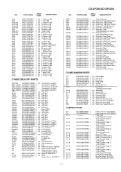
... Square type (without lead wire) VR J .. MODEL NUMBER 2. No. "HOW TO ORDER REPLACEMENT PARTS" To have your nearest SHARP Parts Distributor to replace parts with " " are important for the electrolytic capacitors, error is ±20%. For U.S.A. DESCRIPTION For location of SHARP Parts Distributor, Please call Toll-Free; 1-800-BE-SHARP MARK: SPARE PARTS-DELIVERY SECTION Explanation of CD-XP300 (main unit) and CP-XP300 (speaker system). The 13th character represents...
... Square type (without lead wire) VR J .. MODEL NUMBER 2. No. "HOW TO ORDER REPLACEMENT PARTS" To have your nearest SHARP Parts Distributor to replace parts with " " are important for the electrolytic capacitors, error is ±20%. For U.S.A. DESCRIPTION For location of SHARP Parts Distributor, Please call Toll-Free; 1-800-BE-SHARP MARK: SPARE PARTS-DELIVERY SECTION Explanation of CD-XP300 (main unit) and CP-XP300 (speaker system). The 13th character represents...
Service Manual
Page 57
... Switch,Key Type [Tape] AC Switch,Key Type [Video/Aux] AC Switch,Key Type [Timer/Sleep] AC Switch,Key Type [Tuning/Time Up] AC Switch,Key Type [Rec Pause] AC Switch,Key Type [Memory/Set] AC Switch,Key Type [Tuning/Time Down] AC Switch,Key Type [Clock] AC Switch,Key Type [Volume Up] AC Switch,Key Type [Volume Down] AC Switch,Key Type [Disc Skip] AC Switch,Key Type [Open/Close] AC Switch,Key Type [Equalizer/X-Bass/Demo] CD MECHANISM PARTS...
... Switch,Key Type [Tape] AC Switch,Key Type [Video/Aux] AC Switch,Key Type [Timer/Sleep] AC Switch,Key Type [Tuning/Time Up] AC Switch,Key Type [Rec Pause] AC Switch,Key Type [Memory/Set] AC Switch,Key Type [Tuning/Time Down] AC Switch,Key Type [Clock] AC Switch,Key Type [Volume Up] AC Switch,Key Type [Volume Down] AC Switch,Key Type [Disc Skip] AC Switch,Key Type [Open/Close] AC Switch,Key Type [Equalizer/X-Bass/Demo] CD MECHANISM PARTS...


