

Service Manual
Page 1
... MAIN PARTS .. 9 ADJUSTMENT 10 TROUBLESHOOTING 37 FUNCTION TABLE OF IC 41 CONTENTS Page IMPORTANT SERVICE NOTES (FOR U.S.A. S1306CDE600// MINI COMPONENT SYSTEM MODEL CD-E600 CD-E600 Mini Component System consisting of user-safety the set should be restored to its original condition and only parts identical to be used for the CD-E600/CD-E66, which is a minor-modification model of the CD-E700/CD-E77, This manual, therefore, describes only the changed points from the service manual...
... MAIN PARTS .. 9 ADJUSTMENT 10 TROUBLESHOOTING 37 FUNCTION TABLE OF IC 41 CONTENTS Page IMPORTANT SERVICE NOTES (FOR U.S.A. S1306CDE600// MINI COMPONENT SYSTEM MODEL CD-E600 CD-E600 Mini Component System consisting of user-safety the set should be restored to its original condition and only parts identical to be used for the CD-E600/CD-E66, which is a minor-modification model of the CD-E700/CD-E77, This manual, therefore, describes only the changed points from the service manual...

Service Manual
Page 2
... VOM with the AC line cord plug connection reversed. ONLY) BEFORE RETURNING THE AUDIO PRODUCT (Fire & Shock Hazard) Before returning the audio product to 0.2 milliamp. Any reading of 0.3 volt RMS (this corresponds to the user, perform the following manner. * Plug the AC line cord directly into a 120 volt AC outlet. * Using two clip leads, connect a 1.5 kohm, 10 watt resistor paralleled by a 0.15...
... VOM with the AC line cord plug connection reversed. ONLY) BEFORE RETURNING THE AUDIO PRODUCT (Fire & Shock Hazard) Before returning the audio product to 0.2 milliamp. Any reading of 0.3 volt RMS (this corresponds to the user, perform the following manner. * Plug the AC line cord directly into a 120 volt AC outlet. * Using two clip leads, connect a 1.5 kohm, 10 watt resistor paralleled by a 0.15...
Service Manual
Page 3
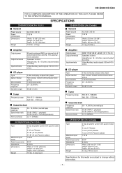
... (15.9 lbs.) Amplifier Output power Output terminals Input terminals CD player Type Signal readout D/A converter Frequency response Dynamic range 85 watts minimum RMS per channel into 6 ohms from 60 Hz to 20 kHz, 10% total harmonic distortion Speakers: 6 ohms Headphones: 16 - 50 ohms (recommended: 32 ohms) Video/Auxiliary (audio signal): 500 mV/47 k ohms 3-disc multi-play compact disc player Non-contact, 3-beam semiconductor laser pickup 1-bit D/A converter 20 - 20,000 Hz 90 dB (1 kHz) Tuner Frequency range FM: 87...
... (15.9 lbs.) Amplifier Output power Output terminals Input terminals CD player Type Signal readout D/A converter Frequency response Dynamic range 85 watts minimum RMS per channel into 6 ohms from 60 Hz to 20 kHz, 10% total harmonic distortion Speakers: 6 ohms Headphones: 16 - 50 ohms (recommended: 32 ohms) Video/Auxiliary (audio signal): 500 mV/47 k ohms 3-disc multi-play compact disc player Non-contact, 3-beam semiconductor laser pickup 1-bit D/A converter 20 - 20,000 Hz 90 dB (1 kHz) Tuner Frequency range FM: 87...

Service Manual
Page 4
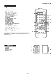
... Time Down Button 4 9. Equalizer Mode Select Button 13. Disc Skip Button 10 17. Tape 2 Cassette Compartment 18. CD Track Down or Fast Reverse, Tape 2 Rewind, Tuner Preset Down Button 22. CD Play or Repeat, Tape Play Button 19 25. Disc Number Indicators 2. CD Play Indicator 3. Extra Bass Indicator 8. Tape Record Indicator 13. AC Power Cord 1 3. Video/Auxiliary (Audio Signal) Input Jacks 5. Memory/Set Button 4. Tuning and Time Up Button 8. Tape (1 2) Button 20. FM Stereo Mode Indicator 5. FM Stereo Receiving Indicator 6. NCD Repeat Play Indicator 12. Disc...
... Time Down Button 4 9. Equalizer Mode Select Button 13. Disc Skip Button 10 17. Tape 2 Cassette Compartment 18. CD Track Down or Fast Reverse, Tape 2 Rewind, Tuner Preset Down Button 22. CD Play or Repeat, Tape Play Button 19 25. Disc Number Indicators 2. CD Play Indicator 3. Extra Bass Indicator 8. Tape Record Indicator 13. AC Power Cord 1 3. Video/Auxiliary (Audio Signal) Input Jacks 5. Memory/Set Button 4. Tuning and Time Up Button 8. Tape (1 2) Button 20. FM Stereo Mode Indicator 5. FM Stereo Receiving Indicator 6. NCD Repeat Play Indicator 12. Disc...
Service Manual
Page 5
... the remote control only. Disc Number Select Buttons 3. Tape 2 Record Pause Button 5. Equalizer Mode Select Button 7. CD Random Button 12. Program Clear Button 4 14. Tape (1 2) Button 9 21. Tuner (Band) Button 8. Power On/Stand-by Button 3 10. CD Play or Repeat, Tape Play Button 8 19. Tweeter 1 2. Video/Auxiliary Button 20. CD-E600/CD-E66 Remote control 1 1. Extra Bass Button 11. Woofer 3. CD Pause Button 5 16. CD Memory Button 13. Speaker Wire 2 3 4 - 5 - Passive Radiator 4. CD Button 9. Direct Search Buttons 4. CD-E600/CD...
... the remote control only. Disc Number Select Buttons 3. Tape 2 Record Pause Button 5. Equalizer Mode Select Button 7. CD Random Button 12. Program Clear Button 4 14. Tape (1 2) Button 9 21. Tuner (Band) Button 8. Power On/Stand-by Button 3 10. CD Play or Repeat, Tape Play Button 8 19. Tweeter 1 2. Video/Auxiliary Button 20. CD-E600/CD-E66 Remote control 1 1. Extra Bass Button 11. Woofer 3. CD Pause Button 5 16. CD Memory Button 13. Speaker Wire 2 3 4 - 5 - Passive Radiator 4. CD Button 9. Direct Search Buttons 4. CD-E600/CD...

Service Manual
Page 6
... protect the optical pickup from electrostatic damage. Hook N1) x2 7-6 2. After removing the connector for the optical pickup from the wall outlet before disassembling. 4. Screw A1) x4 6-1 2 Side Panel (Left/Right) 1. Screw B1) x8 6-1 3 CD Tray Cover/ 1. Flat Cable E3) x1 4. Note 3: 1. Turn on the power supply, .. 6-2 CD Player Unit open the changer manually. (Fig. 6-3) 1. Screw F1) x2 7-1 2. Flat Wire F3) x1 7 Display PWB...
... protect the optical pickup from electrostatic damage. Hook N1) x2 7-6 2. After removing the connector for the optical pickup from the wall outlet before disassembling. 4. Screw A1) x4 6-1 2 Side Panel (Left/Right) 1. Screw B1) x8 6-1 3 CD Tray Cover/ 1. Flat Cable E3) x1 4. Note 3: 1. Turn on the power supply, .. 6-2 CD Player Unit open the changer manually. (Fig. 6-3) 1. Screw F1) x2 7-1 2. Flat Wire F3) x1 7 Display PWB...

Service Manual
Page 10
... L VIDEO IN AUX L9 DI 1 R R 16 CE 2 TAPE L 10 IC601 CLK 24 R 15 TUNER L 11 R 14 LC75341 AUDIO PROCESSOR 21 R 4L CD L 12 R 13 7 8 17 18 3 -20dB ATT Q601 Q602 TAPE 1 L-CH P.B. Q105 Q106 Q114 ERASE HEAD SWITCHING Q112 Q113 BIAS Q111 OSC L103 SWITCHING Q109 BIAS Q110 Q107 Q108 MUTING REC/PLAY T1/T2 BIAS Figure 10 BLOCK DIAGRAM (2/3) - 10 - CD-E600/CD...
... L VIDEO IN AUX L9 DI 1 R R 16 CE 2 TAPE L 10 IC601 CLK 24 R 15 TUNER L 11 R 14 LC75341 AUDIO PROCESSOR 21 R 4L CD L 12 R 13 7 8 17 18 3 -20dB ATT Q601 Q602 TAPE 1 L-CH P.B. Q105 Q106 Q114 ERASE HEAD SWITCHING Q112 Q113 BIAS Q111 OSC L103 SWITCHING Q109 BIAS Q110 Q107 Q108 MUTING REC/PLAY T1/T2 BIAS Figure 10 BLOCK DIAGRAM (2/3) - 10 - CD-E600/CD...

Service Manual
Page 11
... VOLTAGE REGULATOR D802 F802 5A/125V F801 5A/125V D803 D804 F803 2A/125V F804 2A/125V Q801 T.F. CD-E600/CD-E66 +B3 B T Q601 Q602 REC/PLAY T1/T2 BIAS 12 FL701 FL DISPLAY 5 12 13 14 19 27 41 44 45 Q705 +B4 55 40 25 13 48 46 VDD 70... 4.194304 MHz RESET Q709 +B4 SP. D905 D906 RX701 1 REMOTE SENSOR 3 2 +B4 KEY SW701-SW707 SW711-SW718 SW721-SW726 +B PROTECT +B6 TO CD SECTION +B2 JK701 HEADPHONES Q906 +B5 M901 M FAN MOTOR L 1 R 15 9 8 VL+ VL- PT801 MAIN POWER TRANSFORMER D842~ D845 RL841 AC POWER SUPPLY CORD AC 120 V, 60 Hz PT841 SUB POWER TRANSFORMER Figure 11...
... VOLTAGE REGULATOR D802 F802 5A/125V F801 5A/125V D803 D804 F803 2A/125V F804 2A/125V Q801 T.F. CD-E600/CD-E66 +B3 B T Q601 Q602 REC/PLAY T1/T2 BIAS 12 FL701 FL DISPLAY 5 12 13 14 19 27 41 44 45 Q705 +B4 55 40 25 13 48 46 VDD 70... 4.194304 MHz RESET Q709 +B4 SP. D905 D906 RX701 1 REMOTE SENSOR 3 2 +B4 KEY SW701-SW707 SW711-SW718 SW721-SW726 +B PROTECT +B6 TO CD SECTION +B2 JK701 HEADPHONES Q906 +B5 M901 M FAN MOTOR L 1 R 15 9 8 VL+ VL- PT801 MAIN POWER TRANSFORMER D842~ D845 RL841 AC POWER SUPPLY CORD AC 120 V, 60 Hz PT841 SUB POWER TRANSFORMER Figure 11...

Service Manual
Page 12
CD-E600/CD-E66 A CNS601 R-CH 1 BI601 1 2 A_GND 2 3 L-CH 3 4 CD_GND 4 5 CD_+B 5 6 +B +B 6 7 D_GND 7 8 B 8 LD+7V 9 +B R619 L-CH 330 10 CNP5 TO CD SERVO PWB P21 12-D GND ( A_GND) 11 12 R_CH 13 LD+7V R618 330 14 D_GND (DRIVER) A_5V +B 15 D_5V +B 16 17 GND (CD_GND) C CD(A_GND) 18 19 GND (D_GND) TO POWER...6 T2_L2 7 TAPE 2 CNP102 RECORD/ PLAYBACK HEAD G Q603 KTC3199 GR Q604 KTC3199 GR FM SIGNAL PLAYBACK SIGNAL RECORD SIGNAL CD SIGNAL VIDEO SIGNAL R605 10K C609 ... 11 L2 C623 1/50 12 L1 + + AUX DECK TUNER CD IC601 - - - - - - ROUT 21...
CD-E600/CD-E66 A CNS601 R-CH 1 BI601 1 2 A_GND 2 3 L-CH 3 4 CD_GND 4 5 CD_+B 5 6 +B +B 6 7 D_GND 7 8 B 8 LD+7V 9 +B R619 L-CH 330 10 CNP5 TO CD SERVO PWB P21 12-D GND ( A_GND) 11 12 R_CH 13 LD+7V R618 330 14 D_GND (DRIVER) A_5V +B 15 D_5V +B 16 17 GND (CD_GND) C CD(A_GND) 18 19 GND (D_GND) TO POWER...6 T2_L2 7 TAPE 2 CNP102 RECORD/ PLAYBACK HEAD G Q603 KTC3199 GR Q604 KTC3199 GR FM SIGNAL PLAYBACK SIGNAL RECORD SIGNAL CD SIGNAL VIDEO SIGNAL R605 10K C609 ... 11 L2 C623 1/50 12 L1 + + AUX DECK TUNER CD IC601 - - - - - - ROUT 21...

Service Manual
Page 13
... SW_5V M_+13.5V T_BIAS REC/PLAY A_+10V T_T1/T2 S_MUTE D_GND +B-PROTECT DI CLK DO CE L103 330µH C140 47/25 C139 0.039(ML) CNP701B 1 2 3 4 5 6 7 8 9 10 11 12 13 14 15 16 1 16 CNP701A TO DISPLAY PWB P18 1-F FFC701 7 8 9 10 11 12 Figure 13 SCHEMATIC DIAGRAM (2/10) - 13 - C150 47/25 C630... 390P C690 390P R693 33K R692 33K CHASIS L-CH JK690 AUX/VIDEO IN R-CH TO TUNER SECTION P15 11-H TUN_R 1 A GND 2 TUN_L 3 DO 4 CE 5 DI 6 CLK 7 D_GND 8 +B A_+10V 9 A_+10V D1 CLK DO CE +B 100 C130 0.0033 220/10 0.022 C124 270P REC/PLAY T-T1 T2 C133 22/50 C132 47/25 0.022...
... SW_5V M_+13.5V T_BIAS REC/PLAY A_+10V T_T1/T2 S_MUTE D_GND +B-PROTECT DI CLK DO CE L103 330µH C140 47/25 C139 0.039(ML) CNP701B 1 2 3 4 5 6 7 8 9 10 11 12 13 14 15 16 1 16 CNP701A TO DISPLAY PWB P18 1-F FFC701 7 8 9 10 11 12 Figure 13 SCHEMATIC DIAGRAM (2/10) - 13 - C150 47/25 C630... 390P C690 390P R693 33K R692 33K CHASIS L-CH JK690 AUX/VIDEO IN R-CH TO TUNER SECTION P15 11-H TUN_R 1 A GND 2 TUN_L 3 DO 4 CE 5 DI 6 CLK 7 D_GND 8 +B A_+10V 9 A_+10V D1 CLK DO CE +B 100 C130 0.0033 220/10 0.022 C124 270P REC/PLAY T-T1 T2 C133 22/50 C132 47/25 0.022...

Service Manual
Page 14
... C313 22P (CH) R309 10K CF303 D305 DS1SS133 C308 R311 4.7P 100K (CH) FM OSC. R365 10K C362 3 3/50 CD-E600/CD-E66 C302 0.001 A AM TRACKING C338 D301 0.001 DS1SS133 C323 0.022 T303 AM ANTENNA C330 15P (UJ) C331 0.047 C332 0.022 D302 DS1SS133 B T306 AM OSC. T302 FM IF C312 0.022 3 1 TP301... Y OSC BUFFER C381 12P(CH) C39 1/5 22 21 20 AOUT VSS X IN X OUT X352 4.5 MHz I LC CE F C382 15P(CH) 1 2 3 R374 1K +B R375 470 G FM SIGNAL +B AM SIGNAL R381 10K C394 47/25 H • NOTES ON SCHEMATIC DIAGRAM can be found on page 29. 1 2 3 4 5 6 Figure 14...
... C313 22P (CH) R309 10K CF303 D305 DS1SS133 C308 R311 4.7P 100K (CH) FM OSC. R365 10K C362 3 3/50 CD-E600/CD-E66 C302 0.001 A AM TRACKING C338 D301 0.001 DS1SS133 C323 0.022 T303 AM ANTENNA C330 15P (UJ) C331 0.047 C332 0.022 D302 DS1SS133 B T306 AM OSC. T302 FM IF C312 0.022 3 1 TP301... Y OSC BUFFER C381 12P(CH) C39 1/5 22 21 20 AOUT VSS X IN X OUT X352 4.5 MHz I LC CE F C382 15P(CH) 1 2 3 R374 1K +B R375 470 G FM SIGNAL +B AM SIGNAL R381 10K C394 47/25 H • NOTES ON SCHEMATIC DIAGRAM can be found on page 29. 1 2 3 4 5 6 Figure 14...

Service Manual
Page 16
... CD-E600/CD-E66 - POWER AMP. -VCC CH2 OUT +VCC CH1 OUT A 1 2 3 4 5 6 7 8 9 10 11 12 13 14 C908 15 470P FM SIGNAL... 15 +B SW_5V 23 +B D_GND 14 DRIVER GND G GND (CD_GND) 17 GND (D_GND) 19 18 CD(A_GND) GND (M_GND) 26 R859 22K...+B 7 6 7 8 7 8 SUB_B 9 8 +B VF2 CHASSIS CNP802 1 -VF 2 P_IN 3 VF1 4 FW701 5 FROM DISPLAY PWB 6 P19 12-E UNSW_ 5. AC_ H • NOTES ON SCHEMATIC DIAGRAM can be found on page 29. 1 2 3 4 5 6 Figure 16 SCHEMATIC DIAGRAM (5/10) - 16 - L-CH CH1 IC901 STK43209 (2CH) (85W / CH) R-CH IC901 + CH2 STK43209 -
... CD-E600/CD-E66 - POWER AMP. -VCC CH2 OUT +VCC CH1 OUT A 1 2 3 4 5 6 7 8 9 10 11 12 13 14 C908 15 470P FM SIGNAL... 15 +B SW_5V 23 +B D_GND 14 DRIVER GND G GND (CD_GND) 17 GND (D_GND) 19 18 CD(A_GND) GND (M_GND) 26 R859 22K...+B 7 6 7 8 7 8 SUB_B 9 8 +B VF2 CHASSIS CNP802 1 -VF 2 P_IN 3 VF1 4 FW701 5 FROM DISPLAY PWB 6 P19 12-E UNSW_ 5. AC_ H • NOTES ON SCHEMATIC DIAGRAM can be found on page 29. 1 2 3 4 5 6 Figure 16 SCHEMATIC DIAGRAM (5/10) - 16 - L-CH CH1 IC901 STK43209 (2CH) (85W / CH) R-CH IC901 + CH2 STK43209 -

Service Manual
Page 17
...L_OUT Q906 KTC3203 Y CNP971 CD-E600/CD-E66 D912 DS1SS133 R947 15K C931 10/50 CNS971 2 M 2 + - SP_L-CH_GND - PT801 MAIN POWER TRANSFORMER FW802 1 4 RL841 1 4 PT841 SUB POWER TRANSFORMER 7 8 9 10 11 12 Figure 17 SCHEMATIC DIAGRAM (6/10) - 17 -... M901 FAN MOTOR 1 1 R949 1K R950 68K WTM901 M_+13.5V 1 SP_RLY R_CH GND L_CH 5 FW901 1 5 HEADPHONES PWB-A3 CNP705 1 2 3 4 5 JK701 HEADPHONES + SP_L-CH + SP_R-CH 6 OHMS MIN - SP_R-CH_GND SO901 SPEAKER...
...L_OUT Q906 KTC3203 Y CNP971 CD-E600/CD-E66 D912 DS1SS133 R947 15K C931 10/50 CNS971 2 M 2 + - SP_L-CH_GND - PT801 MAIN POWER TRANSFORMER FW802 1 4 RL841 1 4 PT841 SUB POWER TRANSFORMER 7 8 9 10 11 12 Figure 17 SCHEMATIC DIAGRAM (6/10) - 17 -... M901 FAN MOTOR 1 1 R949 1K R950 68K WTM901 M_+13.5V 1 SP_RLY R_CH GND L_CH 5 FW901 1 5 HEADPHONES PWB-A3 CNP705 1 2 3 4 5 JK701 HEADPHONES + SP_L-CH + SP_R-CH 6 OHMS MIN - SP_R-CH_GND SO901 SPEAKER...

Service Manual
Page 18
CD-E600/CD...G10 G09 G08 FL701 FL DISPLAY 45 44 43 42 ...60 59 58 57 56 55 MIC SW D 1K 54 O/C_SW...MAIN PWB 10 T_T1/T2 P13 10-H CNP701B 9 A_+10V 8 REC/PLAY 7 T_BIAS 6 M_+13V 5 SW_5V 4 +B +B SP_DET 3 SP_RLY 2 -20dB 1 1 CNP701A G TAPE MECHANISM PWB-F FFC702 1 1 T2 RUN 1 2 2 +MTR SOL2... SOL 3 SOL 4 3 SOL1 4 F_REC 5 R740 4.7K H M - + 5 6 T1 RUN 6 7 GND 7 D710 DS1SS133 D709 DS1SS133 C712 47/25 7 CNP702 • NOTES ON SCHEMATIC DIAGRAM can be found on page 29. 1 2 3 4 Figure 18 SCHEMATIC DIAGRAM...
CD-E600/CD...G10 G09 G08 FL701 FL DISPLAY 45 44 43 42 ...60 59 58 57 56 55 MIC SW D 1K 54 O/C_SW...MAIN PWB 10 T_T1/T2 P13 10-H CNP701B 9 A_+10V 8 REC/PLAY 7 T_BIAS 6 M_+13V 5 SW_5V 4 +B +B SP_DET 3 SP_RLY 2 -20dB 1 1 CNP701A G TAPE MECHANISM PWB-F FFC702 1 1 T2 RUN 1 2 2 +MTR SOL2... SOL 3 SOL 4 3 SOL1 4 F_REC 5 R740 4.7K H M - + 5 6 T1 RUN 6 7 GND 7 D710 DS1SS133 D709 DS1SS133 C712 47/25 7 CNP702 • NOTES ON SCHEMATIC DIAGRAM can be found on page 29. 1 2 3 4 Figure 18 SCHEMATIC DIAGRAM...

Service Manual
Page 29
... K and M are subject to change for maintaining the safety of the set . Besides, the one measured by Digital Multimeter between such a section and the chas- NO SW713 SW714 SW715 SW716 SW717 SW718 SW721 SW722 SW723 SW724 SW725 SW726 DESCRIPTION VIDEO/AUX TAPE STOP PLAY FAST FORWARD FAST REWIND X-BASS/DEMO EQUALIZER OPEN/CLOSE DISC SKIP VOLUME UP VOLUME DOWN TYPES OF TRANSISTOR AND...
... K and M are subject to change for maintaining the safety of the set . Besides, the one measured by Digital Multimeter between such a section and the chas- NO SW713 SW714 SW715 SW716 SW717 SW718 SW721 SW722 SW723 SW724 SW725 SW726 DESCRIPTION VIDEO/AUX TAPE STOP PLAY FAST FORWARD FAST REWIND X-BASS/DEMO EQUALIZER OPEN/CLOSE DISC SKIP VOLUME UP VOLUME DOWN TYPES OF TRANSISTOR AND...
Service Manual
Page 33
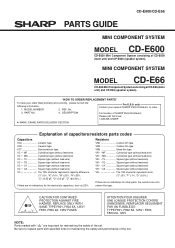
...; TQ Square type (without lead wire) VC • • CY Square type (without lead wire) VC • • CZ Square type (without lead wire) VR J .. "HOW TO ORDER REPLACEMENT PARTS" To have your nearest SHARP Parts Distributor to replace parts with " " are important for maintaining the safety and performance of the set . REF. For U.S.A. PARTS GUIDE CD-E600/CD-E66 MINI COMPONENT SYSTEM MODEL CD-E600 CD-E600 Mini Component System consisting of the...
...; TQ Square type (without lead wire) VC • • CY Square type (without lead wire) VC • • CZ Square type (without lead wire) VR J .. "HOW TO ORDER REPLACEMENT PARTS" To have your nearest SHARP Parts Distributor to replace parts with " " are important for maintaining the safety and performance of the set . REF. For U.S.A. PARTS GUIDE CD-E600/CD-E66 MINI COMPONENT SYSTEM MODEL CD-E600 CD-E600 Mini Component System consisting of the...

Service Manual
Page 37
...,Cassette [Tape 2] AF Panel,AMP. [CD-E600] AF Panel,AMP. [CD-E66] AF Button,Power/Tuning [CD-E600] AF Button,Power/Tuning [CD-E66] AE Button,Open/Close [CD-E600] AE Button,Open/Close [CD-E66] AF Button,Operation A [CD-E600] AF Button,Operation A [CD-E66] AF Button,Operation B [CD-E600] AF Button,Operation B [CD-E66] AG Button,Function [CD-E600] AG Button,Function [CD-E66] AE Button,X-BASS/Equalizer AC Cover,Sensor AB Cover,Timer LED AB Cassette Spring,Tape 1 AB Cassette Spring,Tape 2 AD Damper AD Badge,SHARP AL Button,Volume AN Side Panel Ass'y,Left [CD-E600] - 4 - PART CODE PRICE RANK...
...,Cassette [Tape 2] AF Panel,AMP. [CD-E600] AF Panel,AMP. [CD-E66] AF Button,Power/Tuning [CD-E600] AF Button,Power/Tuning [CD-E66] AE Button,Open/Close [CD-E600] AE Button,Open/Close [CD-E66] AF Button,Operation A [CD-E600] AF Button,Operation A [CD-E66] AF Button,Operation B [CD-E600] AF Button,Operation B [CD-E66] AG Button,Function [CD-E600] AG Button,Function [CD-E66] AE Button,X-BASS/Equalizer AC Cover,Sensor AB Cover,Timer LED AB Cassette Spring,Tape 1 AB Cassette Spring,Tape 2 AD Damper AD Badge,SHARP AL Button,Volume AN Side Panel Ass'y,Left [CD-E600] - 4 - PART CODE PRICE RANK...

Service Manual
Page 38
... Rear Panel [CD-E600 for U.S.A.] AM Rear Panel [CD-E66 for U.S.A.] AM Rear Panel [CD-E600 for Canada] AM Rear Panel [CD-E66 for Canada] AF Polyethylene Bag,Unit AD Pad,Support AB Polyethylene Bag,Accessories ACCESSORIES QANTL0007AWZZ J TINSE0493AWZZ J TINSK0147AWZZ J TINSZ0881AWZZ J TLABR1296AWZZ J TLABR1297AWZZ J TLABZ0593AWZZ J TLABZ1322AWZZ J TLABZ1332AWZZ J RRMCG0358AWSA J GFTAT1017AWSA J AK AM/FM Loop Antenna AE Operation Manual [For U.S.A.] AF Operation Manual [For Canada] AB Quick Guide [For U.S.A. Only] AB Label,Bar Code [CD-E66...
... Rear Panel [CD-E600 for U.S.A.] AM Rear Panel [CD-E66 for U.S.A.] AM Rear Panel [CD-E600 for Canada] AM Rear Panel [CD-E66 for Canada] AF Polyethylene Bag,Unit AD Pad,Support AB Polyethylene Bag,Accessories ACCESSORIES QANTL0007AWZZ J TINSE0493AWZZ J TINSK0147AWZZ J TINSZ0881AWZZ J TLABR1296AWZZ J TLABR1297AWZZ J TLABZ0593AWZZ J TLABZ1322AWZZ J TLABZ1332AWZZ J RRMCG0358AWSA J GFTAT1017AWSA J AK AM/FM Loop Antenna AE Operation Manual [For U.S.A.] AF Operation Manual [For Canada] AB Quick Guide [For U.S.A. Only] AB Label,Bar Code [CD-E66...

Service Manual
Page 39
... Panel,Right [CP-E600] AT Side Panel,Right [CP-E66] AS Passive Radiator AB Screw,ø4×16mm AA Screw,ø3×12mm AC Screw,ø4×35mm AC Screw,ø4×16mm AC Label,Specifications [CP-E600] AC Label,Specifications [CP-E66] AC Felt AL Speaker Cord Ass'y (with Capacitor C1,2) Cushion,Foot AZ Woofer AR Tweeter PACKING PARTS...
... Panel,Right [CP-E600] AT Side Panel,Right [CP-E66] AS Passive Radiator AB Screw,ø4×16mm AA Screw,ø3×12mm AC Screw,ø4×35mm AC Screw,ø4×16mm AC Label,Specifications [CP-E600] AC Label,Specifications [CP-E66] AC Felt AL Speaker Cord Ass'y (with Capacitor C1,2) Cushion,Foot AZ Woofer AR Tweeter PACKING PARTS...
Service Manual
Page 44
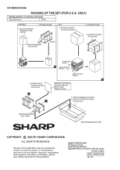
... A Label, Feature [Tape1] BOTTOM Label, Feature [Tape2] B 92LBAG1460C1 Polyethylene Bag, Accessories AM/FM Loop Antenna Operation Manual Quick Guide Remote Control A B SPAKC1548AWZZ [CD-E600] SPAKC1575AWZZ [CD-E66] Packing Case SPAKZ0895AWZZ Pad, Support Not Replacement Item COPYRIGHT © 2003 BY SHARP CORPORATION ALL RIGHTS RESERVED. SHARP CORPORATION AV Systems Group Audio Systems Division Higashihiroshima, Hiroshima 739-0192, Japan Printed in any form or by any...
... A Label, Feature [Tape1] BOTTOM Label, Feature [Tape2] B 92LBAG1460C1 Polyethylene Bag, Accessories AM/FM Loop Antenna Operation Manual Quick Guide Remote Control A B SPAKC1548AWZZ [CD-E600] SPAKC1575AWZZ [CD-E66] Packing Case SPAKZ0895AWZZ Pad, Support Not Replacement Item COPYRIGHT © 2003 BY SHARP CORPORATION ALL RIGHTS RESERVED. SHARP CORPORATION AV Systems Group Audio Systems Division Higashihiroshima, Hiroshima 739-0192, Japan Printed in any form or by any...


