
Service Manual
Page 1
CD-E500 CD-E55/E44 SERVICE MANUAL No. S3333CDE500// Illustration CD-E500/E55 Illustration CD-E44 MINI COMPONENT SYSTEM MODEL CD-E500 CD-E500 Mini Component System consisting of CD-E55 (main unit) and CP-E55 (speaker system). CONTENTS Page IMPORTANT SERVICE NOTES (FOR U.S.A. ONLY) SHARP CORPORATION This document has been published to be used for after sales service only. MODEL CD-E55 CD-E55 Mini Component System consisting...
CD-E500 CD-E55/E44 SERVICE MANUAL No. S3333CDE500// Illustration CD-E500/E55 Illustration CD-E44 MINI COMPONENT SYSTEM MODEL CD-E500 CD-E500 Mini Component System consisting of CD-E55 (main unit) and CP-E55 (speaker system). CONTENTS Page IMPORTANT SERVICE NOTES (FOR U.S.A. ONLY) SHARP CORPORATION This document has been published to be used for after sales service only. MODEL CD-E55 CD-E55 Mini Component System consisting...
Service Manual
Page 2
... current in series with the AC line cord plug connection reversed. FOR A COMPLETE DESCRIPTION OF THE OPERATION OF THIS UNIT, PLEASE REFER TO THE OPERATION MANUAL. Inspect all exposed metal cabinet parts and a known earth ground, such as insulating materials, cabinet, terminal board, adjustment and compartment covers or shields, mechanical ... safety checks. 1. To be sure that hardware is excessive and indicates a potential shock hazard which must be corrected before returning the audio product to 0.2 milliamp. CD-E500 CD-E55/E44 IMPORTANT SERVICE NOTES (FOR U.S.A.
... current in series with the AC line cord plug connection reversed. FOR A COMPLETE DESCRIPTION OF THE OPERATION OF THIS UNIT, PLEASE REFER TO THE OPERATION MANUAL. Inspect all exposed metal cabinet parts and a known earth ground, such as insulating materials, cabinet, terminal board, adjustment and compartment covers or shields, mechanical ... safety checks. 1. To be sure that hardware is excessive and indicates a potential shock hazard which must be corrected before returning the audio product to 0.2 milliamp. CD-E500 CD-E55/E44 IMPORTANT SERVICE NOTES (FOR U.S.A.
Service Manual
Page 5
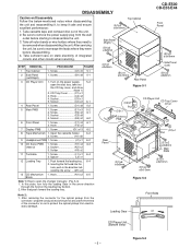
...;3x10mm Figure 5-2 Front Side Loading Gear or CD Player Unit (Bottom View) - 5 - DISASSEMBLY CD-E500 CD-E55/E44 Caution on the power supply, .. 5-2 open the changer manually. (Fig. 5-3) 1. Socket C3) x1 5. Screw D1) x8 5-2 5 Main PWB 1. Note 1) 2. Socket K2) x2 3. After that,push foward the loading tray. After servicing the unit, be removed when disassembling the...
...;3x10mm Figure 5-2 Front Side Loading Gear or CD Player Unit (Bottom View) - 5 - DISASSEMBLY CD-E500 CD-E55/E44 Caution on the power supply, .. 5-2 open the changer manually. (Fig. 5-3) 1. Socket C3) x1 5. Screw D1) x8 5-2 5 Main PWB 1. Note 1) 2. Socket K2) x2 3. After that,push foward the loading tray. After servicing the unit, be removed when disassembling the...
Service Manual
Page 57
... TINSE0118SJZZ J AE Operation Manual [CD-E44] TINSE0123SJZZ J AE Operation Manual [CD-E500/E55 For U.S.A.] TINSE0124SJZZ J AD Quick Guide [CD-E44] TINSE0126SJZZ J AD Quick Guide [CD-E500/E55 For U.S.A.] TINSZ0192SJZZ J Operation Manual [CD-E500/E55 For Canada] RRMCG0063SJSA J AP Remote Control P.W.B. CD Servo PWB-F ---- -- T/T Motor (Supplied at REF No.238, Changer Unit) PWB-H1,2(219-11) 9GD192114325 J Tape Mechanism OTHER SERVICE PARTS UDSKA0004AFZZ J AZ...
... TINSE0118SJZZ J AE Operation Manual [CD-E44] TINSE0123SJZZ J AE Operation Manual [CD-E500/E55 For U.S.A.] TINSE0124SJZZ J AD Quick Guide [CD-E44] TINSE0126SJZZ J AD Quick Guide [CD-E500/E55 For U.S.A.] TINSZ0192SJZZ J Operation Manual [CD-E500/E55 For Canada] RRMCG0063SJSA J AP Remote Control P.W.B. CD Servo PWB-F ---- -- T/T Motor (Supplied at REF No.238, Changer Unit) PWB-H1,2(219-11) 9GD192114325 J Tape Mechanism OTHER SERVICE PARTS UDSKA0004AFZZ J AZ...


