
Service Manual
Page 1
... published to be used for after sales service only. MODEL CD-E44 CD-E44 Mini Component System consisting of CD-E44 (main unit) and CP-E44 (speaker system). • In the interests of user-safety the set should be restored to its original condition and only parts identical to change without notice. ONLY) ...2 SPECIFICATIONS ...2 NAMES OF PARTS ...3 DISASSEMBLY ...5 REMOVING AND REINSTALLING THE MAIN PARTS ...7 ADJUSTMENT ...10 TEST MODE ...11 NOTES ON SCHEMATIC DIAGRAM ...15 TYPES OF...
... published to be used for after sales service only. MODEL CD-E44 CD-E44 Mini Component System consisting of CD-E44 (main unit) and CP-E44 (speaker system). • In the interests of user-safety the set should be restored to its original condition and only parts identical to change without notice. ONLY) ...2 SPECIFICATIONS ...2 NAMES OF PARTS ...3 DISASSEMBLY ...5 REMOVING AND REINSTALLING THE MAIN PARTS ...7 ADJUSTMENT ...10 TEST MODE ...11 NOTES ON SCHEMATIC DIAGRAM ...15 TYPES OF...
Service Manual
Page 2
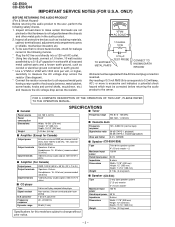
... user, perform the following manner. * Plug the AC line cord directly into 8 ohms from 100 Hz to 20 kHz, 10% total harmonic distortion Speakers: 8 ohms Headphones: 16 - 50 ohms (recommended: 32 ohms) Video/Auxiliary (audio signal): 500 mV/47 k ohms s Amplifier (For Canada) Output power Output terminals Input terminals RMS: 100 W (50 W + 50 W) (10 % T.H.D.) Speakers: 8 ohms Headphones: 16 - 50 ohms (recommended: 32 ohms) Video/Auxiliary (audio signal): 500 mV/47 k ohms s CD player Type Signal readout D/A converter Frequency response Dynamic range 3-disc multi-play compact disc player...
... user, perform the following manner. * Plug the AC line cord directly into 8 ohms from 100 Hz to 20 kHz, 10% total harmonic distortion Speakers: 8 ohms Headphones: 16 - 50 ohms (recommended: 32 ohms) Video/Auxiliary (audio signal): 500 mV/47 k ohms s Amplifier (For Canada) Output power Output terminals Input terminals RMS: 100 W (50 W + 50 W) (10 % T.H.D.) Speakers: 8 ohms Headphones: 16 - 50 ohms (recommended: 32 ohms) Video/Auxiliary (audio signal): 500 mV/47 k ohms s CD player Type Signal readout D/A converter Frequency response Dynamic range 3-disc multi-play compact disc player...
Service Manual
Page 3
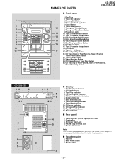
...22 24. Disc Number Indicators 2. FM Stereo Receiving Indicator 6. Video/Auxiliary (Audio Signal) Input Jacks 2. Clock Button 6. Equalizer Mode Select Button 15 13. CD Button 17 19. Sleep Indicator s Rear panel 1. s Speaker system 1. Power On/Stand-by Button 5. Tape 2 Cassette Compartment 18. Tape Play Indicator 4. Cooling Fan 3. Timer Set Indicator 3. Tuning and Time Up Button 8. Tape (1 2) Button 20. Tape Record Indicator 13. Bass Reflex Ducts 3. Disc Skip Button 17. CD Track Up or Fast Forward, Tape 2 Fast Forward, 23 Tuner Preset Up Button 24 25...
...22 24. Disc Number Indicators 2. FM Stereo Receiving Indicator 6. Video/Auxiliary (Audio Signal) Input Jacks 2. Clock Button 6. Equalizer Mode Select Button 15 13. CD Button 17 19. Sleep Indicator s Rear panel 1. s Speaker system 1. Power On/Stand-by Button 5. Tape 2 Cassette Compartment 18. Tape Play Indicator 4. Cooling Fan 3. Timer Set Indicator 3. Tuning and Time Up Button 8. Tape (1 2) Button 20. Tape Record Indicator 13. Bass Reflex Ducts 3. Disc Skip Button 17. CD Track Up or Fast Forward, Tape 2 Fast Forward, 23 Tuner Preset Up Button 24 25...
Service Manual
Page 4
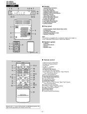
... Stereo Receiving Indicator 6. CD Repeat Play Indicator 12. Tape Record Indicator 13. CD Pause Button 20. Extra Bass Button 21 21. AC Power Input Jack 4. s Speaker system 1. Bass Reflex Ducts 3. Tuning and Time Down Button 8. Disc Number Select Buttons 12. Tuner (Band) Button 17 13. Memory Indicator 7. Cooling Fan 3. FM/AM Loop Antenna Jack 5. Program Clear Button 4 13 7. CD Random Button 15. Video/Auxiliary Button 8 14. Extra Bass Indicator 8. CD Button 4. Memory Button 6. CD Play or Repeat, Tape Play Button 20 18. Speaker Wire s Remote control...
... Stereo Receiving Indicator 6. CD Repeat Play Indicator 12. Tape Record Indicator 13. CD Pause Button 20. Extra Bass Button 21 21. AC Power Input Jack 4. s Speaker system 1. Bass Reflex Ducts 3. Tuning and Time Down Button 8. Disc Number Select Buttons 12. Tuner (Band) Button 17 13. Memory Indicator 7. Cooling Fan 3. FM/AM Loop Antenna Jack 5. Program Clear Button 4 13 7. CD Random Button 15. Video/Auxiliary Button 8 14. Extra Bass Indicator 8. CD Button 4. Memory Button 6. CD Play or Repeat, Tape Play Button 20 18. Speaker Wire s Remote control...
Service Manual
Page 10
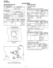
...: 8 ohms) Test Stage Frequency Frequency Display Setting/ Instrument Adjusting Connection Point FM Band - former T304 fully counter- CD-E500 CD-E55/E44 ADJUSTMENT MECHANISM SECTION TUNER SECTION • Driving Force Check Torque Meter Play: DM-300 Specified Value Tape 1: Over 80 g Tape 2: Over 80 g fL: Low-range frequency fH: High-range frequency • AM IF/RF Signal generator: 400 Hz, 30%, AM modulated • Torque Check Torque Meter Specified Value Test Stage Frequency Frequency Setting/ Instrument Display Adjusting Connection Parts Play...
...: 8 ohms) Test Stage Frequency Frequency Display Setting/ Instrument Adjusting Connection Point FM Band - former T304 fully counter- CD-E500 CD-E55/E44 ADJUSTMENT MECHANISM SECTION TUNER SECTION • Driving Force Check Torque Meter Play: DM-300 Specified Value Tape 1: Over 80 g Tape 2: Over 80 g fL: Low-range frequency fH: High-range frequency • AM IF/RF Signal generator: 400 Hz, 30%, AM modulated • Torque Check Torque Meter Specified Value Test Stage Frequency Frequency Setting/ Instrument Display Adjusting Connection Parts Play...
Service Manual
Page 11
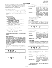
... invalid. "MEMORY/SET"...... "MEMORY/SET"...... TEST MODE CD-E500 CD-E55/E44 The test mode applied to this microcomputer has three modes, namely the ordinary test mode for adjustment or measurement, the aging test mode, and the self-diagnosis test mode for the following buttons to be pressed. When turning the POWER on with remote control buttons, test modes are different depending on destinations at initial settings. 2. FL Test Mode (TEST 5 CLOCK + VOLUME DOWN 6. Step 2 Mode Press the "MEMORY/SET" button in the...
... invalid. "MEMORY/SET"...... "MEMORY/SET"...... TEST MODE CD-E500 CD-E55/E44 The test mode applied to this microcomputer has three modes, namely the ordinary test mode for adjustment or measurement, the aging test mode, and the self-diagnosis test mode for the following buttons to be pressed. When turning the POWER on with remote control buttons, test modes are different depending on destinations at initial settings. 2. FL Test Mode (TEST 5 CLOCK + VOLUME DOWN 6. Step 2 Mode Press the "MEMORY/SET" button in the...
Service Manual
Page 12
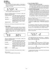
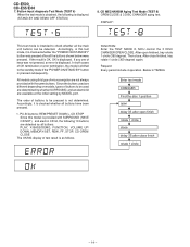
... display indicates the playback passage time as in this test mode. • The TUNER TEST02 mode is obtained with the ordinary operations of tuner (radio) test mode The tuner test mode is obtained, the following buttons to initialize memory. When the tuner test mode is intended to step 1. Test mode and power turned off to shift to obtain the ordinary operation while the data is turned off POWER to the ordinary standby mode. Step 5 Mode When the CD initialization operation...
... display indicates the playback passage time as in this test mode. • The TUNER TEST02 mode is obtained with the ordinary operations of tuner (radio) test mode The tuner test mode is obtained, the following buttons to initialize memory. When the tuner test mode is intended to step 1. Test mode and power turned off to shift to obtain the ordinary operation while the data is turned off POWER to the ordinary standby mode. Step 5 Mode When the CD initialization operation...
Service Manual
Page 13
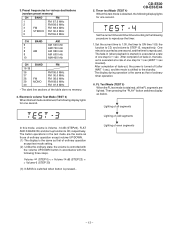
.... 1.Set the current time to 1:00, the timer to ON time 1:05, the function to CD, and volume to the standby. After completion of ordinary timer operation. 6. The fade-in the test mode are lighted. Then pressing the "PLAY" button switches display as that of fade-in accordance with the following display lights for one second, and the timer is pressed.. CD-E500 CD-E55/E44 5. FL Test Mode (TEST 5) When the FL test mode...
.... 1.Set the current time to 1:00, the timer to ON time 1:05, the function to CD, and volume to the standby. After completion of ordinary timer operation. 6. The fade-in the test mode are lighted. Then pressing the "PLAY" button switches display as that of fade-in accordance with the following display lights for one second, and the timer is pressed.. CD-E500 CD-E55/E44 5. FL Test Mode (TEST 5) When the FL test mode...
Service Manual
Page 14
...) 8. PLAY, X-BASS/DEMO, FUNCTION, VOLUME UP/ DOWN, MEMORY/SET, REW, FF, STOP, CD-OPEN/ CLOSE The OK/NG display of keys was pressed after close finished, tray rotate 1 circle (360 degree) again. The order of OK termination or error termination, the mode is displayed. Since the buttons used are determined by whether SURROUND, and an electric lid are available at the initial setting by MODEL port...
...) 8. PLAY, X-BASS/DEMO, FUNCTION, VOLUME UP/ DOWN, MEMORY/SET, REW, FF, STOP, CD-OPEN/ CLOSE The OK/NG display of keys was pressed after close finished, tray rotate 1 circle (360 degree) again. The order of OK termination or error termination, the mode is displayed. Since the buttons used are determined by whether SURROUND, and an electric lid are available at the initial setting by MODEL port...
Service Manual
Page 15
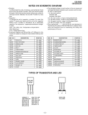
...; Schematic diagram and Wiring Side of P.W.Board for maintaining the safety and performance of the set . In the tuner section, indicates AM indicates FM stereo 2. In the deck section, a tape is the one with no signal given. 1. NO SW711 SW712 SW713 SW714 SW715 SW719 SW720 SW721 SW722 SW723 SW724 SW801 SW802 SW803 DESCRIPTION MEMORY/SET TUNING/TIME DOWN TUNING/TIME UP TIMER/SLEEP CLOCK EQUALIZER VOLUME...
...; Schematic diagram and Wiring Side of P.W.Board for maintaining the safety and performance of the set . In the tuner section, indicates AM indicates FM stereo 2. In the deck section, a tape is the one with no signal given. 1. NO SW711 SW712 SW713 SW714 SW715 SW719 SW720 SW721 SW722 SW723 SW724 SW801 SW802 SW803 DESCRIPTION MEMORY/SET TUNING/TIME DOWN TUNING/TIME UP TIMER/SLEEP CLOCK EQUALIZER VOLUME...
Service Manual
Page 22
... R807 47K 3 2 Q806 KRC107 M R825 10K 270 H • NOTES ON SCHEMATIC DIAGRAM can be found on page 15. 1 2 3 4 5 6 Figure 22 SCHEMATIC DIAGRAM (3/11) - 22 - CD-E500 CD-E55/E44 Q814 KSC1815 GR C809 82P L(T1) R(T1) L(T2) R(T2) R836 47 TAPE MECHANISM ASS'Y(219) MAIN PWB-A(2/3) A PLAYBACK SIGNAL TAPE 1 RECORD SIGNAL PLAYBACK HEAD (219-7) R-CH L-CH CNW801 1 1 2 2 3 3 TI_R A_GND T1_L C803...
... R807 47K 3 2 Q806 KRC107 M R825 10K 270 H • NOTES ON SCHEMATIC DIAGRAM can be found on page 15. 1 2 3 4 5 6 Figure 22 SCHEMATIC DIAGRAM (3/11) - 22 - CD-E500 CD-E55/E44 Q814 KSC1815 GR C809 82P L(T1) R(T1) L(T2) R(T2) R836 47 TAPE MECHANISM ASS'Y(219) MAIN PWB-A(2/3) A PLAYBACK SIGNAL TAPE 1 RECORD SIGNAL PLAYBACK HEAD (219-7) R-CH L-CH CNW801 1 1 2 2 3 3 TI_R A_GND T1_L C803...
Service Manual
Page 29
... X-BASS /DEMO R751 1K RX701 GP1UM271 REMOTE SENSOR 123 C709 100/10 C710 0.047 R760 C708 47 100P EQUALIZER VOLUME UP VOLUME DOWN OPEN/CLOSE DISC SKIP VIDEO/AUX TAPE PRESET DOWN PLAY/REPEAT PRESET UP STOP SW719 SW720 SW721 SW703 SW704 SW705 SW706 SW707 SW708 SW709 SW710 R765 75K TUNER (BAND) CD R766 15K REC/PAUSE R767 8.2K MEMORY/SET R768 5.6K TUNING TIME R769 DOWN 3.9K TUNING TIME...
... X-BASS /DEMO R751 1K RX701 GP1UM271 REMOTE SENSOR 123 C709 100/10 C710 0.047 R760 C708 47 100P EQUALIZER VOLUME UP VOLUME DOWN OPEN/CLOSE DISC SKIP VIDEO/AUX TAPE PRESET DOWN PLAY/REPEAT PRESET UP STOP SW719 SW720 SW721 SW703 SW704 SW705 SW706 SW707 SW708 SW709 SW710 R765 75K TUNER (BAND) CD R766 15K REC/PAUSE R767 8.2K MEMORY/SET R768 5.6K TUNING TIME R769 DOWN 3.9K TUNING TIME...
Service Manual
Page 40
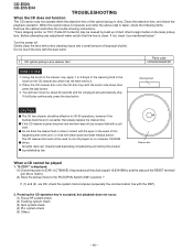
... hear music for 30-50 operations, however if the brushes become very wet then wipe off . If the CD cleaner brushes become worn out earlier then please replace the cleaner disc. Cleaner disc When a CD cannot be played 1. CD optical pickup Lens cleaner disc Parts code UDSKA0004AFZZ HOW TO USE 1. Using the brush... cabinet and follow the trouble shooting instructions. Turn the power off any adjustment make certain that the lens is displayed. (1) Check the power to IC401 (LC78646E), the presence of the clock signal (16.9344 MHz) and the status of the optical pickup is accepted, but...
... hear music for 30-50 operations, however if the brushes become very wet then wipe off . If the CD cleaner brushes become worn out earlier then please replace the cleaner disc. Cleaner disc When a CD cannot be played 1. CD optical pickup Lens cleaner disc Parts code UDSKA0004AFZZ HOW TO USE 1. Using the brush... cabinet and follow the trouble shooting instructions. Turn the power off any adjustment make certain that the lens is displayed. (1) Check the power to IC401 (LC78646E), the presence of the clock signal (16.9344 MHz) and the status of the optical pickup is accepted, but...
Service Manual
Page 44
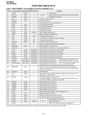
... switching monitor output terminal for rough servo phase control. L Internal signal monitor terminal 1. L Internal signal monitor terminal 4. Digital system power terminal. 39* DOUT 40 TEST 41 LVDD 42 LCHO 43 LVSS Output Input Input Output - B+D signal input terminal. E signal input terminal. Input - Earth terminal for Left channel. D/A output. microcomputer. L Internal signal monitor terminal 3. Must be connected to 0 V, or set by commands from the 26 CONT5 Input/Output Input Mode General-purpose I /O terminal 4. CD-E500 CD-E55/E44 FUNCTION...
... switching monitor output terminal for rough servo phase control. L Internal signal monitor terminal 1. L Internal signal monitor terminal 4. Digital system power terminal. 39* DOUT 40 TEST 41 LVDD 42 LCHO 43 LVSS Output Input Input Output - B+D signal input terminal. E signal input terminal. Input - Earth terminal for Left channel. D/A output. microcomputer. L Internal signal monitor terminal 3. Must be connected to 0 V, or set by commands from the 26 CONT5 Input/Output Input Mode General-purpose I /O terminal 4. CD-E500 CD-E55/E44 FUNCTION...
Service Manual
Page 45
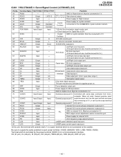
... DO Output (H) Data output port. (N-ch. Chip reset signal input port. LASER power detected signal input port. 80 LDD Output - Right channel D/A converter GND for Digital filter & D/A 51 XVSS - - Oscillator Oscillator Crystal Oscillator Power supply for Microprocessor. 69 VSS - - Must be connect to 0 V.) 57 ASDFIN Input - Power supply for crystal oscillator. Terminal Name Input/Output Setting in Reset Function 44 RVSS 45 RCHO 46 RVDD - When not used, General purpose input/ General...
... DO Output (H) Data output port. (N-ch. Chip reset signal input port. LASER power detected signal input port. 80 LDD Output - Right channel D/A converter GND for Digital filter & D/A 51 XVSS - - Oscillator Oscillator Crystal Oscillator Power supply for Microprocessor. 69 VSS - - Must be connect to 0 V.) 57 ASDFIN Input - Power supply for crystal oscillator. Terminal Name Input/Output Setting in Reset Function 44 RVSS 45 RCHO 46 RVDD - When not used, General purpose input/ General...
Service Manual
Page 48
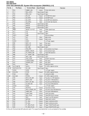
... Input Tape 2 RUN PULSE input. In this unit, the terminal with asterisk mark (*) is not connected to GND. 52-67 S20-S35 P5-P20 Output FL(VFD) segment driver. 68 S36 DISC_NO_SW Input Tray disc no. Port Name Terminal Name Input/Output Function 1 P16 TIMER_LED Output Timer LED control. 2* P17 RDS_DATA Input/Output Open 3* P30 RDS_CLE Input/Output Open 4 P31 CD_CE Output CD DSP CE output. 5 P32 CD_RES Output CD DSP reset. 6 P33 CD_DRF Input CD DRF level...
... Input Tape 2 RUN PULSE input. In this unit, the terminal with asterisk mark (*) is not connected to GND. 52-67 S20-S35 P5-P20 Output FL(VFD) segment driver. 68 S36 DISC_NO_SW Input Tray disc no. Port Name Terminal Name Input/Output Function 1 P16 TIMER_LED Output Timer LED control. 2* P17 RDS_DATA Input/Output Open 3* P30 RDS_CLE Input/Output Open 4 P31 CD_CE Output CD DSP CE output. 5 P32 CD_RES Output CD DSP reset. 6 P33 CD_DRF Input CD DRF level...
Service Manual
Page 51
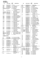
... REPLACEMENT PARTS" To have your nearest SHARP Parts Distributor to replace parts with " " are no indications for other parts, the resistors are ±5% carbon-film type. MODEL NUMBER 2. MODEL CD-E44 CD-E44 Mini Component System consisting of CD-E55 (main unit) and CP-E55 (speaker system). PART NO. 4. MODEL CD-E55 CD-E55 Mini Component System consisting of CD-E44 (main unit) and CP-E44 (speaker system). No. PARTS GUIDE CD-E500 CD-E55/E44 MINI COMPONENT SYSTEM MODEL CD-E500 CD-E500 Mini Component System consisting of the set...
... REPLACEMENT PARTS" To have your nearest SHARP Parts Distributor to replace parts with " " are no indications for other parts, the resistors are ±5% carbon-film type. MODEL NUMBER 2. MODEL CD-E44 CD-E44 Mini Component System consisting of CD-E55 (main unit) and CP-E55 (speaker system). PART NO. 4. MODEL CD-E55 CD-E55 Mini Component System consisting of CD-E44 (main unit) and CP-E44 (speaker system). No. PARTS GUIDE CD-E500 CD-E55/E44 MINI COMPONENT SYSTEM MODEL CD-E500 CD-E500 Mini Component System consisting of the set...
Service Manual
Page 56
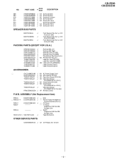
...,Cassette,Right AD Cover,Remote Sensor AD Cover,Timer LED AL Rear Panel [CD-E44] Rear Panel [CD-E500 For U.S.A.] AL Rear Panel [CD-E55 For U.S.A.] Rear Panel [CD-E55 For Canada] Rear Panel [CD-E500 For Canada] AE SHARP Badge AD Button,Power [CD-E44/55] AD Button,Power [CD-E500] AF Button,Function [CD-E44/55] AF Button,Function [CD-E500] AF Button,Stop/Play [CD-E44/55] AF Button,Stop/Play [CD-E300] AD Button,X-BASS AF Button,Volume [CD-E44/55] AF Button,Volume [CD-E500] AE Button,Operation [CD-E44/55] AE Button,Operation [CD-E500] Tape Mechanism Ass'y Belt,FF...
...,Cassette,Right AD Cover,Remote Sensor AD Cover,Timer LED AL Rear Panel [CD-E44] Rear Panel [CD-E500 For U.S.A.] AL Rear Panel [CD-E55 For U.S.A.] Rear Panel [CD-E55 For Canada] Rear Panel [CD-E500 For Canada] AE SHARP Badge AD Button,Power [CD-E44/55] AD Button,Power [CD-E500] AF Button,Function [CD-E44/55] AF Button,Function [CD-E500] AF Button,Stop/Play [CD-E44/55] AF Button,Stop/Play [CD-E300] AD Button,X-BASS AF Button,Volume [CD-E44/55] AF Button,Volume [CD-E500] AE Button,Operation [CD-E44/55] AE Button,Operation [CD-E500] Tape Mechanism Ass'y Belt,FF...
Service Manual
Page 57
...,Feature [Tape 2] ACCESSORIES 1 QACCU0003SJ00 J AH AC Power Supply Cord QANTL0004SJZZ J AG AM Loop/FM Antenna TINSE0118SJZZ J AE Operation Manual [CD-E44] TINSE0123SJZZ J AE Operation Manual [CD-E500/E55 For U.S.A.] TINSE0124SJZZ J AD Quick Guide [CD-E44] TINSE0126SJZZ J AD Quick Guide [CD-E500/E55 For U.S.A.] TINSZ0192SJZZ J Operation Manual [CD-E500/E55 For Canada] RRMCG0063SJSA J AP Remote Control P.W.B. CD Servo PWB-F ---- -- Power/Display/Headphones/ Terminal(Combined Ass'y) PWB-C DCEKSV280SJ03 J -- CD-E500 CD-E55/E44 NO. ASSEMBLY (Not Replacement Item...
...,Feature [Tape 2] ACCESSORIES 1 QACCU0003SJ00 J AH AC Power Supply Cord QANTL0004SJZZ J AG AM Loop/FM Antenna TINSE0118SJZZ J AE Operation Manual [CD-E44] TINSE0123SJZZ J AE Operation Manual [CD-E500/E55 For U.S.A.] TINSE0124SJZZ J AD Quick Guide [CD-E44] TINSE0126SJZZ J AD Quick Guide [CD-E500/E55 For U.S.A.] TINSZ0192SJZZ J Operation Manual [CD-E500/E55 For Canada] RRMCG0063SJSA J AP Remote Control P.W.B. CD Servo PWB-F ---- -- Power/Display/Headphones/ Terminal(Combined Ass'y) PWB-C DCEKSV280SJ03 J -- CD-E500 CD-E55/E44 NO. ASSEMBLY (Not Replacement Item...
Service Manual
Page 59
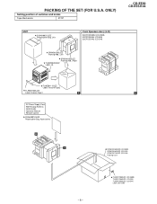
... (CD-E44) Label ,Bar Code ONLY) Setting position of switches and knobs Tape Mechanism STOP UNIT SSAKH0021SJZZ Polyethylene Bag, Unit Top FRONT SPAKA0134SJZZ Packing Add., Left SPAKA0135SJZZ Packing Add., Right TLABS0045SJZZ Label, UL Bottom Front Speakers Ass'y (L/R) B3CPCDE500U (CD-E500) B3CPCDE55U (CD-E55) B3CPCDE44U (CD-E44) FRONT TLABZ0111SJZZ Label, Feature Tape2 TLABZ0106SJZZ Label, Feature Tape1 A AC Power Supply Cord AM/FM Loop Antenna Quick Guide Operation Manual Remote Control...
... (CD-E44) Label ,Bar Code ONLY) Setting position of switches and knobs Tape Mechanism STOP UNIT SSAKH0021SJZZ Polyethylene Bag, Unit Top FRONT SPAKA0134SJZZ Packing Add., Left SPAKA0135SJZZ Packing Add., Right TLABS0045SJZZ Label, UL Bottom Front Speakers Ass'y (L/R) B3CPCDE500U (CD-E500) B3CPCDE55U (CD-E55) B3CPCDE44U (CD-E44) FRONT TLABZ0111SJZZ Label, Feature Tape2 TLABZ0106SJZZ Label, Feature Tape1 A AC Power Supply Cord AM/FM Loop Antenna Quick Guide Operation Manual Remote Control...


