
Assembly Manual
Page 4
When unpacking the box, please inspect all styrofoam and packaging before discarding. CONTENTS Table of the styrofoam packaging. 1 Some parts are packaged on the outside of Contents Hardware 2 Exploded View 4 Parts List 5 Assembly Instructions 6 Important Contact Numbers 18 Attention!
When unpacking the box, please inspect all styrofoam and packaging before discarding. CONTENTS Table of the styrofoam packaging. 1 Some parts are packaged on the outside of Contents Hardware 2 Exploded View 4 Parts List 5 Assembly Instructions 6 Important Contact Numbers 18 Attention!
Assembly Manual
Page 5
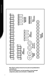
Hardware M8 x 20L HEX HEAD THREAD LOCK (4) M5 x 10L PHILLIPS HEAD (4) M8 WASHER REGULAR (36) M8 x 20L BUTTON HEAD (4) M8 WAVE WASHER (2) M8 x 15L BUTTON HEAD (32) M8 WASHER WIDE (4) Note: Please verify you are missing items, are short quantities, or have all correct parts and quantities before assembling unit. If you have damaged components, please contact Schwinn at 1.800.864.1270 2
Hardware M8 x 20L HEX HEAD THREAD LOCK (4) M5 x 10L PHILLIPS HEAD (4) M8 WASHER REGULAR (36) M8 x 20L BUTTON HEAD (4) M8 WAVE WASHER (2) M8 x 15L BUTTON HEAD (32) M8 WASHER WIDE (4) Note: Please verify you are missing items, are short quantities, or have all correct parts and quantities before assembling unit. If you have damaged components, please contact Schwinn at 1.800.864.1270 2
Assembly Manual
Page 6
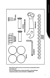
If you have damaged components, please contact Schwinn at 1.800.864.1270 3 HARDWARE M5 x 20L PHILLIPS HEAD (2) COMBO WRENCH (2) COTTER PIN (2) STAPLED TO THE HARDWARE CARD M8 WASHER LOCKING (40) REGULAR (36) M8 x 25L FLAT HEAD THREAD LOCK (6) END CAPS (4) ALLEN WRENCH (1) Note: Please verify you are missing items, are short quantities, or have all correct parts and quantities before assembling unit.
If you have damaged components, please contact Schwinn at 1.800.864.1270 3 HARDWARE M5 x 20L PHILLIPS HEAD (2) COMBO WRENCH (2) COTTER PIN (2) STAPLED TO THE HARDWARE CARD M8 WASHER LOCKING (40) REGULAR (36) M8 x 25L FLAT HEAD THREAD LOCK (6) END CAPS (4) ALLEN WRENCH (1) Note: Please verify you are missing items, are short quantities, or have all correct parts and quantities before assembling unit.
Assembly Manual
Page 8
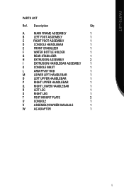
PARTS LIST PARTS LIST Ref. Description Qty A Main Frame Assembly 1 B Left Foot Assembly 1 C Right Foot Assembly 1 D Console HandleBAR 1 E Front Stabilizer 1 F Water Bottle Holder 1 G Rear Stabilizer 1 H Extrusion Assembly 2 I Extrusion ...
PARTS LIST PARTS LIST Ref. Description Qty A Main Frame Assembly 1 B Left Foot Assembly 1 C Right Foot Assembly 1 D Console HandleBAR 1 E Front Stabilizer 1 F Water Bottle Holder 1 G Rear Stabilizer 1 H Extrusion Assembly 2 I Extrusion ...
Assembly Manual
Page 10
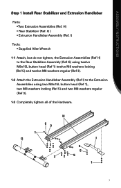
... 5) and twelve M8 washers regular (Ref 3). 1-2 Attach the Extrusion Handlebar Assembly (Ref I 3 5 3 5 1 7 H) • Rear Stabilizer (Ref. ASSEMBLY INSTRUCTIONS Step 1 Install Rear Stabilizer and Extrusion Handlebar Parts: • Two Extrusion Assemblies (Ref. H 53 1 G I ) to the Extrusion Assemblies using two M8x15L button head (Ref 1), two M8 washers locking (Ref 5) and two M8 washers...
... 5) and twelve M8 washers regular (Ref 3). 1-2 Attach the Extrusion Handlebar Assembly (Ref I 3 5 3 5 1 7 H) • Rear Stabilizer (Ref. ASSEMBLY INSTRUCTIONS Step 1 Install Rear Stabilizer and Extrusion Handlebar Parts: • Two Extrusion Assemblies (Ref. H 53 1 G I ) to the Extrusion Assemblies using two M8x15L button head (Ref 1), two M8 washers locking (Ref 5) and two M8 washers...
Assembly Manual
Page 11
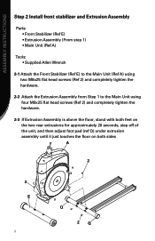
ASSEMBLY INSTRUCTIONS Step 2 Install front stabilizer and Extrusion Assembly Parts: • Front Stabilizer (Ref E) • Extrusion Assembly (From step 1) • Main Unit (Ref A) Tools Supplied Allen Wrench 2-1 Attach the Front Stabilizer (Ref E) to the Main ...
ASSEMBLY INSTRUCTIONS Step 2 Install front stabilizer and Extrusion Assembly Parts: • Front Stabilizer (Ref E) • Extrusion Assembly (From step 1) • Main Unit (Ref A) Tools Supplied Allen Wrench 2-1 Attach the Front Stabilizer (Ref E) to the Main ...
Assembly Manual
Page 12
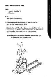
ASSEMBLY INSTRUCTIONS Step 3 Install Console Mast Parts: • Console Mast (Ref K) Main Unit Tools Supplied Allen Wrench 3-1 Connect the wire harness from the Main Unit to pinch the wires when sliding the Console Mast onto the Main Unit K 3 5 1 9 NOTE: Be careful not to the wire harness in the Console Mast. 3-2 Slide the Console Mast (Ref K) down onto the Main Unit and secure using six M8x15L button head (Ref 1), six M8 washers regular (Ref 3) and six M8 washers locking (Ref 5).
ASSEMBLY INSTRUCTIONS Step 3 Install Console Mast Parts: • Console Mast (Ref K) Main Unit Tools Supplied Allen Wrench 3-1 Connect the wire harness from the Main Unit to pinch the wires when sliding the Console Mast onto the Main Unit K 3 5 1 9 NOTE: Be careful not to the wire harness in the Console Mast. 3-2 Slide the Console Mast (Ref K) down onto the Main Unit and secure using six M8x15L button head (Ref 1), six M8 washers regular (Ref 3) and six M8 washers locking (Ref 5).
Assembly Manual
Page 13
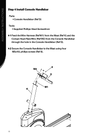
ASSEMBLY INSTRUCTIONS Step 4 Install Console Handlebar Parts: • Console Handlebar (Ref D) Tools Supplied Phillips Head Screwdriver 4-1 Feed the Wire Harness (Ref W1) from the Mast (Ref K) and the Contact Heart Rate Wire (Ref W2) from the Console Handlebar through the hole in the Console Handlebar (Ref D). 4-2 Secure the Console Handlebar to the Mast using four M5x10L phillps screws (Ref 8). 8 W2 D W1 K 10
ASSEMBLY INSTRUCTIONS Step 4 Install Console Handlebar Parts: • Console Handlebar (Ref D) Tools Supplied Phillips Head Screwdriver 4-1 Feed the Wire Harness (Ref W1) from the Mast (Ref K) and the Contact Heart Rate Wire (Ref W2) from the Console Handlebar through the hole in the Console Handlebar (Ref D). 4-2 Secure the Console Handlebar to the Mast using four M5x10L phillps screws (Ref 8). 8 W2 D W1 K 10
Assembly Manual
Page 14
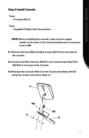
ASSEMBLY INSTRUCTIONS Step 5 Install Console Parts: • Console (Ref U) Tools Supplied Phillips Head Screwdriver NOTE: Before installing the console, make sure the toggle switch on the back of the Console (beside wire connectors) is set to EP. 5-1 Remove the four M5x10 phillps screws (Ref 9) from the back of the console. 5-2 Connect the Wire Harness (Ref W1) and Contact Heart Rate Wire (Ref W2) to the back of the Console. 5-3 Reinstall the Console (Ref U) to the Console Handlebar (Ref D) using the screws removed in Step 5-1. U W2 9 W1 D 11
ASSEMBLY INSTRUCTIONS Step 5 Install Console Parts: • Console (Ref U) Tools Supplied Phillips Head Screwdriver NOTE: Before installing the console, make sure the toggle switch on the back of the Console (beside wire connectors) is set to EP. 5-1 Remove the four M5x10 phillps screws (Ref 9) from the back of the console. 5-2 Connect the Wire Harness (Ref W1) and Contact Heart Rate Wire (Ref W2) to the back of the Console. 5-3 Reinstall the Console (Ref U) to the Console Handlebar (Ref D) using the screws removed in Step 5-1. U W2 9 W1 D 11
Assembly Manual
Page 15
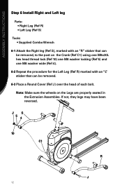
ASSEMBLY INSTRUCTIONS Step 6 Install Right and Left leg Parts: • Right Leg (Ref R) • Left Leg (Ref S) Tools Supplied Combo Wrench 6-1 Attach the Right leg (Ref S), marked with an "R" sticker that can be removed. 6-3 ...
ASSEMBLY INSTRUCTIONS Step 6 Install Right and Left leg Parts: • Right Leg (Ref R) • Left Leg (Ref S) Tools Supplied Combo Wrench 6-1 Attach the Right leg (Ref S), marked with an "R" sticker that can be removed. 6-3 ...
Assembly Manual
Page 16
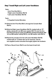
... the hardware 7-4 Place a Round Cover (Ref 6) over the head of each bolt. 6 54 K 6 12 L 10 M Q 13 ASSEMBLY INSTRUCTIONS Step 7 Install Right and Left Lower Handlebars Parts Arm Pivot Rod (Ref L Right Lower Handlebar (Ref Q Left Lower Handlebar (Ref M) Tools 2 Supplied Combo Wrenches 7-1 Slide the Arm Pivot Rod (Ref L) through the Console...
... the hardware 7-4 Place a Round Cover (Ref 6) over the head of each bolt. 6 54 K 6 12 L 10 M Q 13 ASSEMBLY INSTRUCTIONS Step 7 Install Right and Left Lower Handlebars Parts Arm Pivot Rod (Ref L Right Lower Handlebar (Ref Q Left Lower Handlebar (Ref M) Tools 2 Supplied Combo Wrenches 7-1 Slide the Arm Pivot Rod (Ref L) through the Console...
Assembly Manual
Page 17
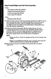
... (Ref 5) and three M8 washers regular(Ref 3). 8-2 Position the Left Foot Assembly (Ref B), marked with an "R". ASSEMBLY INSTRUCTIONS Step 8 Install Right and Left Foot Assembly Parts Foot Mount Plate Qty.2 (Ref T Right Foot Assembly (Ref C Left Foot Assembly (Ref B Arm Cotter Pin (Ref N) Tools Supplied Allen Wrench 8-1 Slide the shaft under...
... (Ref 5) and three M8 washers regular(Ref 3). 8-2 Position the Left Foot Assembly (Ref B), marked with an "R". ASSEMBLY INSTRUCTIONS Step 8 Install Right and Left Foot Assembly Parts Foot Mount Plate Qty.2 (Ref T Right Foot Assembly (Ref C Left Foot Assembly (Ref B Arm Cotter Pin (Ref N) Tools Supplied Allen Wrench 8-1 Slide the shaft under...
Assembly Manual
Page 18
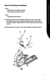
ASSEMBLY INSTRUCTIONS Step 9 Install Upper Handlebars Parts: • Right Upper Handlebar (Ref P) • Left Upper Handlebar (Ref O) Tools Supplied Allen Wrench 9-1 Slide the Upper Left Handlebar (Ref O) into the Lower Left Handlebar and secure using four M8x15l button head (Ref 1) four M8 washers regular (Ref 3) and four M8 washers locking (ref 5). 9-1 Repeat the procedure for the Upper Right Handlebar (Ref P). P 53 1 O 1 35 15
ASSEMBLY INSTRUCTIONS Step 9 Install Upper Handlebars Parts: • Right Upper Handlebar (Ref P) • Left Upper Handlebar (Ref O) Tools Supplied Allen Wrench 9-1 Slide the Upper Left Handlebar (Ref O) into the Lower Left Handlebar and secure using four M8x15l button head (Ref 1) four M8 washers regular (Ref 3) and four M8 washers locking (ref 5). 9-1 Repeat the procedure for the Upper Right Handlebar (Ref P). P 53 1 O 1 35 15
Assembly Manual
Page 19
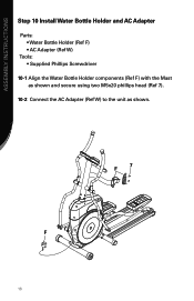
ASSEMBLY INSTRUCTIONS Step 10 Install Water Bottle Holder and AC Adapter Parts: • Water Bottle Holder (Ref F) • AC Adapter (Ref W) Tools Supplied Phillips Screwdriver 10-1 Align the Water Bottle Holder components (Ref F) with the Mast as shown and secure using two M5x20 phillips head (Ref 7). 10-2 Connect the AC Adapter (Ref W) to the unit as shown. F 16 7 F
ASSEMBLY INSTRUCTIONS Step 10 Install Water Bottle Holder and AC Adapter Parts: • Water Bottle Holder (Ref F) • AC Adapter (Ref W) Tools Supplied Phillips Screwdriver 10-1 Align the Water Bottle Holder components (Ref F) with the Mast as shown and secure using two M5x20 phillips head (Ref 7). 10-2 Connect the AC Adapter (Ref W) to the unit as shown. F 16 7 F

Owner's Manual
Page 2
... your progress by tracking time, speed, distance and approximate Calories burned. This Owner's Manual contains all the information you pursue your Schwinn® exercise elliptical trainer. The on Schwinn® craftsmanship and durability as you need to a slimmer and healthier body. Take your exercise and fitness activities. So let's ...ll be an efficient, easy and fun way to accurately monitor your overall percentage of body fat Whether you for making the Schwinn® elliptical trainer a part of fitness. Thank you are general fitness guidelines. CONGRATULATIONS!
... your progress by tracking time, speed, distance and approximate Calories burned. This Owner's Manual contains all the information you pursue your Schwinn® exercise elliptical trainer. The on Schwinn® craftsmanship and durability as you need to a slimmer and healthier body. Take your exercise and fitness activities. So let's ...ll be an efficient, easy and fun way to accurately monitor your overall percentage of body fat Whether you for making the Schwinn® elliptical trainer a part of fitness. Thank you are general fitness guidelines. CONGRATULATIONS!
Owner's Manual
Page 4
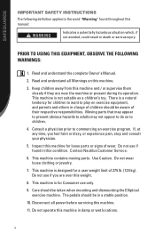
...locations. 4 Inspect this machine. 3. Care should be in charge of children should be taken when mounting and dismounting the Elliptical exercise machine. Moving parts that may appear to present obvious hazards to adults may not appear to do so to commencing an exercise program. Contact...this condition. Keep children away from this machine. 11. There is designed for a user weight limit of wear. This machine contains moving parts. PRIOR TO USING THIS EQUIPMENT, OBSERVE THE FOLLOWING WA�RN� I�N�G�S 1. If, at any time, you are...
...locations. 4 Inspect this machine. 3. Care should be in charge of children should be taken when mounting and dismounting the Elliptical exercise machine. Moving parts that may appear to present obvious hazards to adults may not appear to do so to commencing an exercise program. Contact...this condition. Keep children away from this machine. 11. There is designed for a user weight limit of wear. This machine contains moving parts. PRIOR TO USING THIS EQUIPMENT, OBSERVE THE FOLLOWING WA�RN� I�N�G�S 1. If, at any time, you are...
Owner's Manual
Page 23
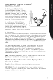
...damage and wear. MAINTENANCE MAINTENANCE OF YOUR SCHWINN® ELLIPTICAL TRAINER Moving your Elliptical Trainer To move the elliptical trainer, carefully but securely lift the rear end of the elliptical trainer and slowly steer the elliptical trainer to wipe your elliptical trainer and computer free of sweat. ...To avoid damaging the finish on the proper use until it is regularly examined for loose, broken, damaged or worn parts. To level the 430, raise or lower the two leveling bolts located on the computer. 23 Weekly: Check for uneven surfaces. Wipe any...
...damage and wear. MAINTENANCE MAINTENANCE OF YOUR SCHWINN® ELLIPTICAL TRAINER Moving your Elliptical Trainer To move the elliptical trainer, carefully but securely lift the rear end of the elliptical trainer and slowly steer the elliptical trainer to wipe your elliptical trainer and computer free of sweat. ...To avoid damaging the finish on the proper use until it is regularly examined for loose, broken, damaged or worn parts. To level the 430, raise or lower the two leveling bolts located on the computer. 23 Weekly: Check for uneven surfaces. Wipe any...
Owner's Manual
Page 25
..., but it in keeping you are exercising in . Remember, if you don't enjoy the space you have done in your home fitness center. Make fitness a part of sticking to an exercise program, be helpful in , even if you are over 30, have health problems or have a history of times a day, "I am...
..., but it in keeping you are exercising in . Remember, if you don't enjoy the space you have done in your home fitness center. Make fitness a part of sticking to an exercise program, be helpful in , even if you are over 30, have health problems or have a history of times a day, "I am...
Owner's Manual
Page 27
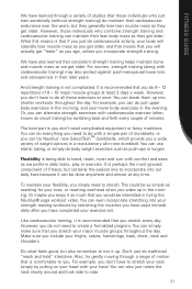
... recommended that you do 8 - 12 repetitions of 8 - 10 major muscle groups at any time. Or, you don't need to you stretch every day. The best part is comfortable to stretch. It is perhaps the most ignored component of fitness, but also remember to side. 27 Like cardiovascular training, it is being...
... recommended that you do 8 - 12 repetitions of 8 - 10 major muscle groups at any time. Or, you don't need to you stretch every day. The best part is comfortable to stretch. It is perhaps the most ignored component of fitness, but also remember to side. 27 Like cardiovascular training, it is being...
Owner's Manual
Page 34
...of goods not complying with its exercise products. See your Authorized Schwinn® Fitness Dealer for any warranty coverage set forth herein, whether express or implied by the use a replacement part not supplied by Nautilus, Nautilus shall not be required. labor This...warranty policies and procedures. WARRANTY LIMITED WARRANTY FOR EXERCISE PRODUCTS All Schwinn® exercise products are in lieu of and exclude all other than an Authorized Schwinn® Fitness Dealer, or use of such unauthorized service or parts. 6. TIME PERIOD Residential Environment: 15 years - Nautilus, Inc...
...of goods not complying with its exercise products. See your Authorized Schwinn® Fitness Dealer for any warranty coverage set forth herein, whether express or implied by the use a replacement part not supplied by Nautilus, Nautilus shall not be required. labor This...warranty policies and procedures. WARRANTY LIMITED WARRANTY FOR EXERCISE PRODUCTS All Schwinn® exercise products are in lieu of and exclude all other than an Authorized Schwinn® Fitness Dealer, or use of such unauthorized service or parts. 6. TIME PERIOD Residential Environment: 15 years - Nautilus, Inc...


