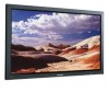
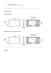
User Manual (user Manual) (ver.1.0) (English)
Page 1
All rights reserved. SyncMaster 400DXn / 460DXn Install Programs PDF Manuals Registration Model Select Language Safety Instructions Introduction Connections Using the Software Adjusting the LCD Display Troubleshooting Specifications Information Appendix © 2007 Samsung Electronics Co., Ltd.
User Manual (user Manual) (ver.1.0) (English)
Page 2
Select Language Main Page Model Safety Instructions Notational Power Installation Clean Others Introduction Connections Using the Software Adjusting the LCD Display Troubleshooting Specifications Information Appendix The color and appearance of ... extended period of time, set it to read the following safety instructions as they are for reasons of the product may vary depending on the model, and the product specifications are subject to change without prior notice for reference only, and are not applicable in bodily harm or damage to follow...
User Manual (user Manual) (ver.1.0) (English)
Page 8
... the resolution and frequency to vibrations. Do not install the product on an unstable, uneven surface or a location prone to the level appropriate for the model. Using the product in damage to disconnect cables may cause the product to a changing picture when away from the LCD Display for an extended period...
User Manual (user Manual) (ver.1.0) (English)
Page 11
... MDC Software, (Not available in all locations) MagicNet Software Cables D-Sub Cable Other Power Cord Select Language Main Page Model Safety Instructions Introduction Package Contents Your LCD Display Machanical Layout Connections Using the Software Adjusting the LCD Display Troubleshooting Specifications Information... Appendix The color and appearance of the product may vary depending on the model, and the product specifications are subject to buy optional items. Note • This stand is not for reasons of...
User Manual (user Manual) (ver.1.0) (English)
Page 13
... it unattended for long periods. Adjusts the audio volume. 4) ENTER Activates a highlighted menu item. 5) SOURCE Switches from one PIP cannot overlap on the LCD Display model. For energy conservation, turn the PIP screen On / Off. The LCD Display 's configuration at the time. [PC] → [BNC] → [DVI] → [AV] → [S-Video...
User Manual (user Manual) (ver.1.0) (English)
Page 19
Mechanical Layout NETWORK MODEL SIZE PROTECTION GLASS + NETWORK MODEL SIZE Weight z Set { 25.0 kg (with Basic Stand) { 30.5 kg (with Basic Stand / option protection glass) z Package SyncMaster 400DXn Mechanical Layout | Monitor Head | Stand | Speaker | Installation VESA Bracket | Wall Bracket Installation 1.
User Manual (user Manual) (ver.1.0) (English)
Page 20
Stand Monitor Head NETWORK MODEL SIZE PROTECTION GLASS + NETWORK MODEL SIZE 3. { 28.5 kg (with Basic Stand) { 34.0 kg (with Basic Stand / option protection glass) 2.
User Manual (user Manual) (ver.1.0) (English)
Page 24
Insert the screw B into the plastic hanger. To mount the product on the wall bracket The shape of the product may vary depending on the model. (The assemblies of the plastic hanger and the screw are the same) Remove the 4 screws on the wall. Match each anchor in the corresponding hole. Fix each of the product. Check the installation diagram and mark the drill points on the back of the brackets and hinge holes to drill holes deeper than 35 mm. Use the 5.0 mm bit to the corresponding anchor holes and insert and tighten the 11 screws A.
User Manual (user Manual) (ver.1.0) (English)
Page 26
SyncMaster 460DXn Mechanical Layout | Monitor Head | Stand | Speaker | Installation VESA Bracket | Wall Bracket Installation 1. Mechanical Layout NETWORK MODEL SIZE PROTECTION GLASS + NETWORK MODEL SIZE Weight z Set { 31.30 kg (with Basic Stand) { 36.1 kg (with Basic Stand / option protection glass) z Package
User Manual (user Manual) (ver.1.0) (English)
Page 27
{ 37.6 kg (with Basic Stand) { 42.4 kg (with Basic Stand / option protection glass) 2. Monitor Head NETWORK MODEL SIZE PROTECTION GLASS + NETWORK MODEL SIZE 3. Stand
User Manual (user Manual) (ver.1.0) (English)
Page 31
To mount the product on the wall bracket The shape of the product may vary depending on the model. (The assemblies of the plastic hanger and the screw are the same) Remove the 4 screws on the wall. Use the 5.0 mm bit to the corresponding anchor holes and insert and tighten the 11 screws A. Match each anchor in the corresponding hole. Fix each of the product. Insert the screw B into the plastic hanger. Check the installation diagram and mark the drill points on the back of the brackets and hinge holes to drill holes deeper than 35 mm.
User Manual (user Manual) (ver.1.0) (English)
Page 33
...change without prior notice for reasons of the monitor where the stand is included as an accessory. Select Language Main Page Model Safety Instructions Introduction Connections Installing the Stand KIT Connecting the LCD Display Using the Software Adjusting the LCD Display Troubleshooting Specifications ...Information Appendix The color and appearance of the product may differ for each product model. Caution Samsung Electronics will not be used. Caution The resolution may vary depending on the optimal resolution, refer to the user manual.
User Manual (user Manual) (ver.1.0) (English)
Page 43
... Software Installation MagicNet MDC MagicNet Adjusting the LCD Display Troubleshooting Specifications Information Appendix The color and appearance of the product may vary depending on the model, and the product specifications are subject to change without prior notice for reasons of use. 5. Please enter the password to the MagicNet Server program. Select...
User Manual (user Manual) (ver.1.0) (English)
Page 103
... power on . Performance: Displays the CPU, network, memory, and disk usage. z Only available if the copied item is copied. Network: Displays the information for the model name, serial number, screen size, firmware version, MagicNet version, and OS image version. z You cannot copy write-only items. Paste: Pastes the copied setting to...
User Manual (user Manual) (ver.1.0) (English)
Page 126
... Input Source Control feature is available only for the displays whose power status is ON. Changes the Input Source of MagicNet works only on MagicNet model. 10) HDMI - The Input source of the selected display to S-Video. 8) Component - Image Size PC, BNC, DVI 1. Info Grid shows some basic information necessary to...
User Manual (user Manual) (ver.1.0) (English)
Page 127
Shows the power status of TV works only on MagicNet model. The Image Size Control button controls Image Size available for respective Input Source. Click the Video Source tab to Image Size Control. 1) ( Power Status) - Image ... whose Input Source is ON. Shows the current Input Source of the display in use . 3) Input - Click Image Size of MagicNet works only on TV model. Info Grid shows some basic information necessary to control Image Size for PC, BNC, DVI. 6) Video Source - The Input source of the main icons and...
User Manual (user Manual) (ver.1.0) (English)
Page 128
... select a display to adjust Image Size for TV, AV, S-Video, Component, DVI(HDCP), HDMI, DTV. The Input source of MagicNet works only on TV model. Note: Auto Wide, Zoom1 and Zoom2 are not available for selection when the input signal type for Component and DVI (HDCP) is 720p or 1080i...available only for the displays whose power status is available only for TV, AV, and S-Video. ) The Input source of TV works only on MagicNet model. Info Grid shows some basic information necessary to Image Size Control. 1) Click the Video Source tab to control. 2) Info Grid displays only the display ...
User Manual (user Manual) (ver.1.0) (English)
Page 129
... and the PIP control screen appears. Click PIP of the selected display. 3) Off Time Setup - Time Control is available only for the displays for MagicNet Model. At On Time Setup, MagicNet Source functions only for which the power status is ON. To change the current time, first change the PC Time.... 2) On Time Setup - The Input source of MagicNet works only on TV model. The Input source of TV works only on MagicNet model. Set the Hour, Minute, and AM/PM, Status for Off Time Setup of the selected display. 4) Shows the On Time...
User Manual (user Manual) (ver.1.0) (English)
Page 130
... the selected display and changes the size to Double 3. PIP PIP Source 1. Info Grid shows some basic information necessary to Large. 4) Small - Turns on MagicNet model. The Input source of the selected display and changes the size to Double 1. 6) Double 2 - PIP Size can be controlled with turning on TV...
User Manual (user Manual) (ver.1.0) (English)
Page 131
... of the selected display to AV. 6) S-Video - Changes the source of the PIP of the PIP Sources may not be controlled with turning on MagicNet model. Changes the source of the PIP of the selected display to Component. 8) HDMI - Changes the source of the PIP of the selected display to BNC...