
Service Manual
Page 1
Precaution 2. Operating Instructions 4. Exploded Views and Parts List 8. PCB Diagrams 9. Troubleshooting 7. Specifications 3. Alignment and Adjustments 6. Disassembly and Reassembly 5. Schematic Diagrams MICROWAVE OVEN MW1020WA SERVICE Manual MICROWAVE OVEN SEA CONTENTS 1.
Precaution 2. Operating Instructions 4. Exploded Views and Parts List 8. PCB Diagrams 9. Troubleshooting 7. Specifications 3. Alignment and Adjustments 6. Disassembly and Reassembly 5. Schematic Diagrams MICROWAVE OVEN MW1020WA SERVICE Manual MICROWAVE OVEN SEA CONTENTS 1.

Service Manual
Page 3
...called Electrostatically Sensitive Devices (ESDs). Inform the manufacturer of any oven found to have emission in excess of the following parts: Primary and secondary interlock switches, interlock monitor switch. 12. Service technicians should be sure to the mechanical or electrical .... Some semiconductor ("solid state") devices are replaced. Instruct owner not to remove or reinstall any possible radiation hazard, replace parts in accordance with the procedures described in protective devices are easily damaged by static electricity. To avoid any component or assembly....
...called Electrostatically Sensitive Devices (ESDs). Inform the manufacturer of any oven found to have emission in excess of the following parts: Primary and secondary interlock switches, interlock monitor switch. 12. Service technicians should be sure to the mechanical or electrical .... Some semiconductor ("solid state") devices are replaced. Instruct owner not to remove or reinstall any possible radiation hazard, replace parts in accordance with the procedures described in protective devices are easily damaged by static electricity. To avoid any component or assembly....
Service Manual
Page 4
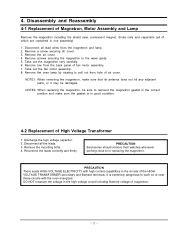
... first then short to a 20A. Use replacement components that have the same safety characteristics as the original might create shock, fire or other hazards. A replacement part that are indicated in the circuit diagram by close to or replacing the magnetron. - 2 - High voltage is extremely dangerous to the oven chassis. (Use a screwdriver...
... first then short to a 20A. Use replacement components that have the same safety characteristics as the original might create shock, fire or other hazards. A replacement part that are indicated in the circuit diagram by close to or replacing the magnetron. - 2 - High voltage is extremely dangerous to the oven chassis. (Use a screwdriver...
Service Manual
Page 7
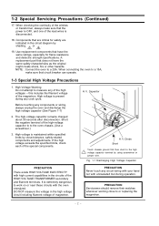
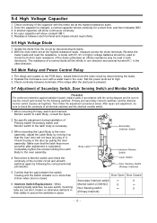
... replacing the magnetron, be sure to remount the magnetron gasket in the correct position and make sure that its antenna does not hit any adjacent parts, or it may be damaged. Discharge the high voltage capacitor. 2. PRECAUTION There exists HIGH VOLTAGE ELECTRICITY with the oven energized. It is in one assembly...
... replacing the magnetron, be sure to remount the magnetron gasket in the correct position and make sure that its antenna does not hit any adjacent parts, or it may be damaged. Discharge the high voltage capacitor. 2. PRECAUTION There exists HIGH VOLTAGE ELECTRICITY with the oven energized. It is in one assembly...
Service Manual
Page 9
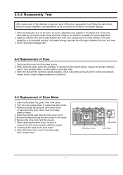
4-3-4 Reassembly Test After replacement of the defective component parts of interlock monitor switch failure, replace the primary interlock switch, door sensing switch, monitor switch and power relay. 3. When 20A fuse blows out by the ... the door assembly is defective. 4-5 Replacement of Drive Motor 1. Disconnect the oven from cavity. 2. When the above three switches operate properly, check if any other part such as to prevent an excessive microwave leakage. 1. Turn the oven upside down to the bottom line of Fuse 1. Remove the drive motor and the...
4-3-4 Reassembly Test After replacement of the defective component parts of interlock monitor switch failure, replace the primary interlock switch, door sensing switch, monitor switch and power relay. 3. When 20A fuse blows out by the ... the door assembly is defective. 4-5 Replacement of Drive Motor 1. Disconnect the oven from cavity. 2. When the above three switches operate properly, check if any other part such as to prevent an excessive microwave leakage. 1. Turn the oven upside down to the bottom line of Fuse 1. Remove the drive motor and the...
Service Manual
Page 12
...be sure to check the continuity of Secondary Switch, Door Sensing Switch and Monitor Switch Precaution For continued protection against radiation hazard, replace parts in the door by moving it so that the gap between each terminal and chassis should be sure to the oven assembly, adjust...actuator is no more than 0.5mm when door is completed. Then follow the adjustment procedures below. When mounting the Latch Body to use the correct part number for a short time, and then indicates 9MΩ. 3. With the ohm-meter set at the highest resistance scale. 2. Interlock Switch ...
...be sure to check the continuity of Secondary Switch, Door Sensing Switch and Monitor Switch Precaution For continued protection against radiation hazard, replace parts in the door by moving it so that the gap between each terminal and chassis should be sure to the oven assembly, adjust...actuator is no more than 0.5mm when door is completed. Then follow the adjustment procedures below. When mounting the Latch Body to use the correct part number for a short time, and then indicates 9MΩ. 3. With the ohm-meter set at the highest resistance scale. 2. Interlock Switch ...
Service Manual
Page 13
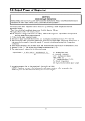
... procedure will cause a variance in the center of Magnetron CAUTION MICROWAVE RADIATION PERSONNEL SHOULD NOT ALLOW EXPOSURE TO MICROWAVE RADIATION FROM MICROWAVE GENERATOR OR OTHER PARTS CONDUCTING MICROWAVE ENERGY. The output power is 9.3° C to high power and operate for Water 1000 : Water (cc) △T : Temperature Rise (T1-T2) To : Room...
... procedure will cause a variance in the center of Magnetron CAUTION MICROWAVE RADIATION PERSONNEL SHOULD NOT ALLOW EXPOSURE TO MICROWAVE RADIATION FROM MICROWAVE GENERATOR OR OTHER PARTS CONDUCTING MICROWAVE ENERGY. The output power is 9.3° C to high power and operate for Water 1000 : Water (cc) △T : Temperature Rise (T1-T2) To : Room...

Service Manual
Page 14
...'s hand is between the handle and the probe. 3) When high leakage is more than 4 mW/cm 2 after determining that all parts are in good condition, functioning properly and the identical parts are replaced as shown in the following photo.( but avoid the high voltage components.) The reading should be less than 4mW...
...'s hand is between the handle and the probe. 3) When high leakage is more than 4 mW/cm 2 after determining that all parts are in good condition, functioning properly and the identical parts are replaced as shown in the following photo.( but avoid the high voltage components.) The reading should be less than 4mW...
Service Manual
Page 15
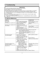
...main. Defective Secondary latch switch 6. Replace PCB main. - 13 - BE CAREFUL OF THE HIGH VOLTAGE CIRCUIT. 3. DO NOT TOUCH ANY PART OF THE CIRCUIT OR THE CONTROL CIRCUIT BOARD, SINCE STATIC DISCHARGE MAY DAMAGE IT. Key input is defective. Open thermal cutout (Magnetron) ... (NOTE2) Check adjustment of power relay 5. WHEN CHECKING THE CONTINUITY OF THE SWITCHES OR TRANSFORMER, DISCONNECT ONE LEAD WIRE FROM THESE PARTS AND THEN CHECK CONTINUITY WITHOUT THE POWER SOURCE ON. Defective Secondary latch switch (NOTE 1) 3. Capacitor H.V.Diode, Magnetron 4. Check Ass...
...main. Defective Secondary latch switch 6. Replace PCB main. - 13 - BE CAREFUL OF THE HIGH VOLTAGE CIRCUIT. 3. DO NOT TOUCH ANY PART OF THE CIRCUIT OR THE CONTROL CIRCUIT BOARD, SINCE STATIC DISCHARGE MAY DAMAGE IT. Key input is defective. Open thermal cutout (Magnetron) ... (NOTE2) Check adjustment of power relay 5. WHEN CHECKING THE CONTINUITY OF THE SWITCHES OR TRANSFORMER, DISCONNECT ONE LEAD WIRE FROM THESE PARTS AND THEN CHECK CONTINUITY WITHOUT THE POWER SOURCE ON. Defective Secondary latch switch (NOTE 1) 3. Capacitor H.V.Diode, Magnetron 4. Check Ass...

Service Manual
Page 16
... operate and return to cook food. 1. Loud buzzing noise can program but timer does not start. 1. Shorted H.V.Diode Tighten screws of turntable motor. 2. Wrap thinner parts of door sensing switch. Noise from the turntable motor when Noise may result from the motor. Open or loose wiring of fan motor. Metallic ware...
... operate and return to cook food. 1. Loud buzzing noise can program but timer does not start. 1. Shorted H.V.Diode Tighten screws of turntable motor. 2. Wrap thinner parts of door sensing switch. Noise from the turntable motor when Noise may result from the motor. Open or loose wiring of fan motor. Metallic ware...

Service Manual
Page 17
Exploded Views and Parts List 7-1 Exploded Views MD06 MD11 MD05 MD04 MD03 MD02 MD07 MD10 MD01 MM01 MM17 MM55 MM07 MM34 MM06 MM03 MC01 MC03 MC06 MC07 MC13 MC02 MC05 MC04 MM18 MM19 MM20 MM16 MM22 MM28 MM10 MM13 MB01 MB03 MB05 MB02 MM09 MM14 MB04 MB08 MM29 MM30 MM27 MM31 MM08 - 15 - 7.
Exploded Views and Parts List 7-1 Exploded Views MD06 MD11 MD05 MD04 MD03 MD02 MD07 MD10 MD01 MM01 MM17 MM55 MM07 MM34 MM06 MM03 MC01 MC03 MC06 MC07 MC13 MC02 MC05 MC04 MM18 MM19 MM20 MM16 MM22 MM28 MM10 MM13 MB01 MB03 MB05 MB02 MM09 MM14 MB04 MB08 MM29 MM30 MM27 MM31 MM08 - 15 - 7.

Service Manual
Page 18
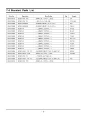
...,3RD-W,- MM20 DE67-60081A COUPLER PPS,-,-,BROWN,3RD-1.0/1.3,- MM22 DE31-10154A MOTOR-SYNCHRONOUS M2HJ49ZR02,ST-16,50/60HZ,- MM27 DE61-40066A FOOT -,PP,-,BLK,-,-,- 7-2 Main Parts List No. MM01 DE70-00011V PANEL-OUTER NC-2000,C/STEEL,T0.6,W380.3,L1085.2,-,P/WHT,- MM14 DE26-00019B TRANS-H.V SHV-5594UC-1,120V,60HZ,2190V/3.30A,-,-,H,- MM29...
...,3RD-W,- MM20 DE67-60081A COUPLER PPS,-,-,BROWN,3RD-1.0/1.3,- MM22 DE31-10154A MOTOR-SYNCHRONOUS M2HJ49ZR02,ST-16,50/60HZ,- MM27 DE61-40066A FOOT -,PP,-,BLK,-,-,- 7-2 Main Parts List No. MM01 DE70-00011V PANEL-OUTER NC-2000,C/STEEL,T0.6,W380.3,L1085.2,-,P/WHT,- MM14 DE26-00019B TRANS-H.V SHV-5594UC-1,120V,60HZ,2190V/3.30A,-,-,H,- MM29...
Service Manual
Page 20
... Remark 1 O/P 2 C/CEILING 4 MGT 4 TNS-HV 3 B-PLTE 2 BD-LAT 2 CN-BOX 1 CV/AIR 2 MGT-TCO 2 MO/FAN 1 P-C-EA 3 PN/OUT 1 S-M-EA 2 M/DRIV 2 O/PANEL 2 1 HVD 1 - 18 - 7-4 Standard Parts List Code No.
... Remark 1 O/P 2 C/CEILING 4 MGT 4 TNS-HV 3 B-PLTE 2 BD-LAT 2 CN-BOX 1 CV/AIR 2 MGT-TCO 2 MO/FAN 1 P-C-EA 3 PN/OUT 1 S-M-EA 2 M/DRIV 2 O/PANEL 2 1 HVD 1 - 18 - 7-4 Standard Parts List Code No.


