
Service Manual
Page 1
Operating Instructions 4. Exploded Views and Parts List 8. Precaution 2. Alignment and Adjustments 6. PCB Diagrams 9. Specifications 3. Troubleshooting 7. MICROWAVE OVEN MW1020WA SERVICE Manual MICROWAVE OVEN SEA CONTENTS 1. Schematic Diagrams Disassembly and Reassembly 5.
Operating Instructions 4. Exploded Views and Parts List 8. Precaution 2. Alignment and Adjustments 6. PCB Diagrams 9. Specifications 3. Troubleshooting 7. MICROWAVE OVEN MW1020WA SERVICE Manual MICROWAVE OVEN SEA CONTENTS 1. Schematic Diagrams Disassembly and Reassembly 5.

Service Manual
Page 2
... hinges and latches. (5) evidence of dropping or abuse. (c) Before turning on microwave power for any service test or inspection within the microwave generating compartments, check the magnetron, wave guide or transmission line, and cavity for proper alignment, integrity, and connections. (d) Any defective or misadjusted components in the interlock, monitor, door seal, and microwave generation and transmission systems shall be repaired, replaced, or adjusted...
... hinges and latches. (5) evidence of dropping or abuse. (c) Before turning on microwave power for any service test or inspection within the microwave generating compartments, check the magnetron, wave guide or transmission line, and cavity for proper alignment, integrity, and connections. (d) Any defective or misadjusted components in the interlock, monitor, door seal, and microwave generation and transmission systems shall be repaired, replaced, or adjusted...

Service Manual
Page 3
... following at no cabinet openings through which people -- always remove the instrument's ground lead last. - 1 - Never alter or add to operate the oven and contact the manufacturer and the center for the particular model being repaired. 13. This product complies with the door open : Instruct the user not to the mechanical or electrical design of the built-in this manual. If the oven operates with Federal...
... following at no cabinet openings through which people -- always remove the instrument's ground lead last. - 1 - Never alter or add to operate the oven and contact the manufacturer and the center for the particular model being repaired. 13. This product complies with the door open : Instruct the user not to the mechanical or electrical design of the built-in this manual. If the oven operates with Federal...
Service Manual
Page 4
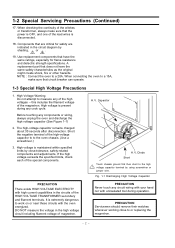
... VOLTAGE ELECTRICITY with uninsulated tool during any circuit wiring with your hand nor with high current capabilities in the circuits of magnetron. DO NOT measure the voltage in the circuit diagram by shading, or . 19. A replacement part that circuit breaker can operate. 1-3 Special High Voltage Precautions 1. PRECAUTION Never touch any cook cycle. When connecting the oven to work on or near these circuits with the oven energized...
... VOLTAGE ELECTRICITY with uninsulated tool during any circuit wiring with your hand nor with high current capabilities in the circuits of magnetron. DO NOT measure the voltage in the circuit diagram by shading, or . 19. A replacement part that circuit breaker can operate. 1-3 Special High Voltage Precautions 1. PRECAUTION Never touch any cook cycle. When connecting the oven to work on or near these circuits with the oven energized...
Service Manual
Page 5
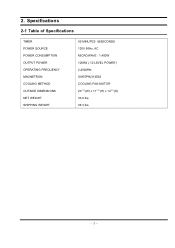
2. Specifications 2-1 Table of Specifications TIMER POWER SOURCE POWER CONSUMPTION OUTPUT POWER OPERATING FREQUENCY MAGNETRON COOLING METHOD OUTSIDE DIMENSIONS NET WEIGHT SHIPPING WEIGHT 99 MINUTES 99SECONDS 120V 60Hz, AC MICROWAVE : 1,400W 1000W ( 10 LEVEL POWER ) 2,450MHz OM75PH(31)ESS COOLING FAN MOTOR 2011/32(W) x 1111/16(H) x 1415/16(D) 33.0 lbs. 36.3 lbs. - 3 -
2. Specifications 2-1 Table of Specifications TIMER POWER SOURCE POWER CONSUMPTION OUTPUT POWER OPERATING FREQUENCY MAGNETRON COOLING METHOD OUTSIDE DIMENSIONS NET WEIGHT SHIPPING WEIGHT 99 MINUTES 99SECONDS 120V 60Hz, AC MICROWAVE : 1,400W 1000W ( 10 LEVEL POWER ) 2,450MHz OM75PH(31)ESS COOLING FAN MOTOR 2011/32(W) x 1111/16(H) x 1415/16(D) 33.0 lbs. 36.3 lbs. - 3 -
Service Manual
Page 7
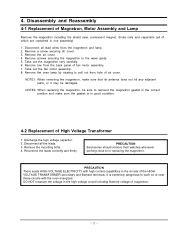
... the magnetron to or replacing the magnetron. Remove the oven lamp by rotating to pull out from the magnetron and lamp. 2. Reconnect the leads correctly and firmly. PRECAUTION Servicemen should remove their watches whenever working close to the wave guide. 5. Remove tow from the back panel of the HIGH VOLTAGE TRANSFORMER secondary and filament terminals. Take out the fan motor assembly. 8. It is in one assembly). 1. Remove the air cover...
... the magnetron to or replacing the magnetron. Remove the oven lamp by rotating to pull out from the magnetron and lamp. 2. Reconnect the leads correctly and firmly. PRECAUTION Servicemen should remove their watches whenever working close to the wave guide. 5. Remove tow from the back panel of the HIGH VOLTAGE TRANSFORMER secondary and filament terminals. Take out the fan motor assembly. 8. It is in one assembly). 1. Remove the air cover...

Service Manual
Page 8
4-3 Replacement of Door Assembly 4-3-1 Removal of the thin metal plate should be 0.5mm or less. Be careful when handling Door "C" because it is fragile. Insertion depth of Door "C" Insert flat screw driver into the gap between Door "E" and Door "A" until you hear the 'tick' sound. 1. Then remove the door assembly. Key Door Spring Door "E" 4-3-3 Removal of Door "E" Following the procedure as shown in the figure, insert and bend a thin metal plate between Door "A" and...
4-3 Replacement of Door Assembly 4-3-1 Removal of the thin metal plate should be 0.5mm or less. Be careful when handling Door "C" because it is fragile. Insertion depth of Door "C" Insert flat screw driver into the gap between Door "E" and Door "A" until you hear the 'tick' sound. 1. Then remove the door assembly. Key Door Spring Door "E" 4-3-3 Removal of Door "E" Following the procedure as shown in the figure, insert and bend a thin metal plate between Door "A" and...
Service Manual
Page 9
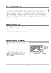
.... 8. Screw the drive motor cover to prevent an excessive microwave leakage. 1. Take out the glass tray, guide roller from base plate by the operation of interlock monitor switch failure, replace the primary interlock switch, door sensing switch, monitor switch and power relay. 3. Turn the oven upside down to the cavity. 6. Remove a screw securing the drive motor cover or disconnect the drive motor cover from cavity. 2. 4-3-4 Reassembly Test After replacement of the defective component parts of the door...
.... 8. Screw the drive motor cover to prevent an excessive microwave leakage. 1. Take out the glass tray, guide roller from base plate by the operation of interlock monitor switch failure, replace the primary interlock switch, door sensing switch, monitor switch and power relay. 3. Turn the oven upside down to the cavity. 6. Remove a screw securing the drive motor cover or disconnect the drive motor cover from cavity. 2. 4-3-4 Reassembly Test After replacement of the defective component parts of the door...

Service Manual
Page 10
Disconnect the connectors from the Ass'y control box. 4. Therefore, applying hot air such as its mounting tabs will be broken. Remove screws securing the control circuit board. 3. Lift up the control circuit board from the control circuit board. 3. If repair work is attached to ground any problems (shorted contacts or uneven surface) can be disassembled as using of Window Display & Membrane Panel 1. When installing new membrane key board, make...
Disconnect the connectors from the Ass'y control box. 4. Therefore, applying hot air such as its mounting tabs will be broken. Remove screws securing the control circuit board. 3. Lift up the control circuit board from the control circuit board. 3. If repair work is attached to ground any problems (shorted contacts or uneven surface) can be disassembled as using of Window Display & Membrane Panel 1. When installing new membrane key board, make...

Service Manual
Page 11
...-4290U 379Ω 10.23Ω 31.91Ω Magnetron Antenna Gasket Plate Cooling Fins - 9 - Before touching any cook cycle. 2. Continuity checks can indicate only an open . Alignment and Adjustments PRECAUTION 1. Remove connectors from the PCB Ass'y and check continuity. 3. 5. High voltage is located on the control circuit board. 2. Remove the low voltage transformer from the transformer terminals and check...
...-4290U 379Ω 10.23Ω 31.91Ω Magnetron Antenna Gasket Plate Cooling Fins - 9 - Before touching any cook cycle. 2. Continuity checks can indicate only an open . Alignment and Adjustments PRECAUTION 1. Remove connectors from the PCB Ass'y and check continuity. 3. 5. High voltage is located on the control circuit board. 2. Remove the low voltage transformer from the transformer terminals and check...
Service Manual
Page 12
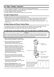
... the oven assembly, adjust the Latch Body by disconnecting the leads. 2. After repair and adjustment, be sure to the latch body is pressed. 5-7 Adjustment of Primary switch Secondary switch and Monitor switch to use the correct part number for a short time, and then indicates 9MΩ. 3. No specific adjustment during installation of Secondary Switch, Door Sensing Switch and Monitor Switch Precaution For continued protection against radiation hazard, replace parts in...
... the oven assembly, adjust the Latch Body by disconnecting the leads. 2. After repair and adjustment, be sure to the latch body is pressed. 5-7 Adjustment of Primary switch Secondary switch and Monitor switch to use the correct part number for a short time, and then indicates 9MΩ. 3. No specific adjustment during installation of Secondary Switch, Door Sensing Switch and Monitor Switch Precaution For continued protection against radiation hazard, replace parts in...
Service Manual
Page 13
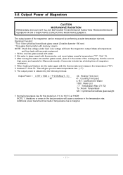
... glass vessel with water. 2. The output power is 9.3° C to high power and operate for 44seconds exactly. (3 seconds included as a holding time of the cooking tray. Low voltage will give you the water temperature rise. (△T) 6. After moving the water into another glass vessel, place it in the center of magnetron oscillation:) 4. Set the oven to 10.5°C at 'HIGH'. When heating...
... glass vessel with water. 2. The output power is 9.3° C to high power and operate for 44seconds exactly. (3 seconds included as a holding time of the cooking tray. Low voltage will give you the water temperature rise. (△T) 6. After moving the water into another glass vessel, place it in the center of magnetron oscillation:) 4. Set the oven to 10.5°C at 'HIGH'. When heating...

Service Manual
Page 14
..., and place the beaker in the center of the oven. 2) Start to operate the oven and measure the leakage by its manufacturer. - 12 - If the leakage testing of the cabinet door seam is taken near the opening of magnetron, the surface of the air guide and the surface of the wave guide as shown in the following photo.( but avoid the...
..., and place the beaker in the center of the oven. 2) Start to operate the oven and measure the leakage by its manufacturer. - 12 - If the leakage testing of the cabinet door seam is taken near the opening of magnetron, the surface of the air guide and the surface of the wave guide as shown in the following photo.( but avoid the...
Service Manual
Page 15
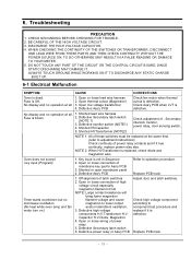
... procedure and replace if it has continuity, replace power relay also. Open thermal cutout (Magnetron) 3. BE CAREFUL OF THE HIGH VOLTAGE CIRCUIT. 3. No display and no microwave oscillation. (No heat while oven lamp and fan motor turn on.) 1. NOTE 1: All of , Secondary interlock monitor, power relay, door sensing switch. Oven does not accept key input (Program) 1. Defective Ass'y PCB Refer to operation procedure. DO NOT TOUCH ANY PART OF THE CIRCUIT OR THE CONTROL CIRCUIT BOARD, SINCE...
... procedure and replace if it has continuity, replace power relay also. Open thermal cutout (Magnetron) 3. BE CAREFUL OF THE HIGH VOLTAGE CIRCUIT. 3. No display and no microwave oscillation. (No heat while oven lamp and fan motor turn on.) 1. NOTE 1: All of , Secondary interlock monitor, power relay, door sensing switch. Oven does not accept key input (Program) 1. Defective Ass'y PCB Refer to operation procedure. DO NOT TOUCH ANY PART OF THE CIRCUIT OR THE CONTROL CIRCUIT BOARD, SINCE...

Service Manual
Page 16
... once or twice while cooking foods such as soup, cocoa, or milk. Defective turntable motor. Metallic ware or cooking dishes touching on 1. it starts to cook food. 1. Turntable motor does not rotate. 1. Ceramic ware trimmed with metallic trimming. Tighten screws of cookware with gold or silver powder also causes sparks. Decrease in mode. Defective Secondary latch switch Oven can be heard. 1. 6-1 Electrical Maltunction(continved) SYMPTOM CAUSE CORRECTIONS Oven lamp and fan motor turn on the oven wall. 2. Replace turntable motor.
... once or twice while cooking foods such as soup, cocoa, or milk. Defective turntable motor. Metallic ware or cooking dishes touching on 1. it starts to cook food. 1. Turntable motor does not rotate. 1. Ceramic ware trimmed with metallic trimming. Tighten screws of cookware with gold or silver powder also causes sparks. Decrease in mode. Defective Secondary latch switch Oven can be heard. 1. 6-1 Electrical Maltunction(continved) SYMPTOM CAUSE CORRECTIONS Oven lamp and fan motor turn on the oven wall. 2. Replace turntable motor.

Service Manual
Page 17
Exploded Views and Parts List 7-1 Exploded Views MD06 MD11 MD05 MD04 MD03 MD02 MD07 MD10 MD01 MM01 MM17 MM55 MM07 MM34 MM06 MM03 MC01 MC03 MC06 MC07 MC13 MC02 MC05 MC04 MM18 MM19 MM20 MM16 MM22 MM28 MM10 MM13 MB01 MB03 MB05 MB02 MM09 MM14 MB04 MB08 MM29 MM30 MM27 MM31 MM08 - 15 - 7.
Exploded Views and Parts List 7-1 Exploded Views MD06 MD11 MD05 MD04 MD03 MD02 MD07 MD10 MD01 MM01 MM17 MM55 MM07 MM34 MM06 MM03 MC01 MC03 MC06 MC07 MC13 MC02 MC05 MC04 MM18 MM19 MM20 MM16 MM22 MM28 MM10 MM13 MB01 MB03 MB05 MB02 MM09 MM14 MB04 MB08 MM29 MM30 MM27 MM31 MM08 - 15 - 7.

Service Manual
Page 18
... DE61-50106A BRACKET-HVC -,SECC,T0.8,W31,L125.8,-,- Code No. MM10 4713-001102 LAMP-INCANDESCENT 125V,-,25W,TRP,-,-,25x62mm MM13 DE66-90113A LEVER-DOOR PP(TB53-GH41),T2.5,-,-,12g,NTR,3RD-W,- MM19 DE92-90189Z ASSY-GUIDE ROLLER 3RD-1.0CUFT,SPS(C832) BROWN,D14.7,- Description Specification MB01 DE96-00115A ASSY BODY LATCH MW850WA,NC2000(BUTTON) MB02 3405-001033 SWITCH-MICRO 125...
... DE61-50106A BRACKET-HVC -,SECC,T0.8,W31,L125.8,-,- Code No. MM10 4713-001102 LAMP-INCANDESCENT 125V,-,25W,TRP,-,-,25x62mm MM13 DE66-90113A LEVER-DOOR PP(TB53-GH41),T2.5,-,-,12g,NTR,3RD-W,- MM19 DE92-90189Z ASSY-GUIDE ROLLER 3RD-1.0CUFT,SPS(C832) BROWN,D14.7,- Description Specification MB01 DE96-00115A ASSY BODY LATCH MW850WA,NC2000(BUTTON) MB02 3405-001033 SWITCH-MICRO 125...
Service Manual
Page 20
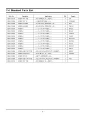
...10195A DE60-10088A DE60-10098A DE60-10012A Description SCREW-TAP TITE SCREW-TAP TH SCREW-WASHER SCREW-WASHER SCREW-A SCREW-A SCREW-A SCREW-A SCREW-A SCREW-A SCREW-A SCREW-A SCREW-A SCREW-ASSY TAP TITE SCREW-STAR POLE SCREW-TAP PH SCREW-ASSY TAP TITE SCREW-TAP TITE Specification -,SWR10,M4,L10,TH,+,-,3,ZPC2,-,-,SUS410,CR,...,-,M4X8,WT,-,SWR10,M4,L10,TH,+,-,3,ZPC2,- 7-4 Standard Parts List Code No. Q'ty Remark 1 O/P 2 C/CEILING 4 MGT 4 TNS-HV 3 B-PLTE 2 BD-LAT 2 CN-BOX 1 CV/AIR 2 MGT-TCO 2 MO/FAN 1 P-C-EA 3 PN/OUT 1 S-M-EA 2 M/DRIV 2 O/PANEL 2 1 HVD 1 - 18 -
...10195A DE60-10088A DE60-10098A DE60-10012A Description SCREW-TAP TITE SCREW-TAP TH SCREW-WASHER SCREW-WASHER SCREW-A SCREW-A SCREW-A SCREW-A SCREW-A SCREW-A SCREW-A SCREW-A SCREW-A SCREW-ASSY TAP TITE SCREW-STAR POLE SCREW-TAP PH SCREW-ASSY TAP TITE SCREW-TAP TITE Specification -,SWR10,M4,L10,TH,+,-,3,ZPC2,-,-,SUS410,CR,...,-,M4X8,WT,-,SWR10,M4,L10,TH,+,-,3,ZPC2,- 7-4 Standard Parts List Code No. Q'ty Remark 1 O/P 2 C/CEILING 4 MGT 4 TNS-HV 3 B-PLTE 2 BD-LAT 2 CN-BOX 1 CV/AIR 2 MGT-TCO 2 MO/FAN 1 P-C-EA 3 PN/OUT 1 S-M-EA 2 M/DRIV 2 O/PANEL 2 1 HVD 1 - 18 -

Service Manual
Page 23
... RED RED DOOR SENSING SWITCH BOTTOM MONITOR SWITCH CENTER BLK WHT HIGH VOLTAGE TRANSFORMER RED WHT POWER RELAY - 21 - SYMBOL ORG WHT BLK BLU RED COLOR ORANGE WHITE BLACK BLUE RED NOTE: FOR SERVICE REPLACEMENT USE 16 GA 105° C THERMOPLASTIC COVERED WIRE EXCEPT FOR HIGH VOLTAGE LEADS OR AS NOTED ON SPECIAL LEADS. Schematic Diagrams 9-1 Schematic Diagrams NOTE: CIRCUIT SHOWN WITH DOOR IS OPENED POSITION.
... RED RED DOOR SENSING SWITCH BOTTOM MONITOR SWITCH CENTER BLK WHT HIGH VOLTAGE TRANSFORMER RED WHT POWER RELAY - 21 - SYMBOL ORG WHT BLK BLU RED COLOR ORANGE WHITE BLACK BLUE RED NOTE: FOR SERVICE REPLACEMENT USE 16 GA 105° C THERMOPLASTIC COVERED WIRE EXCEPT FOR HIGH VOLTAGE LEADS OR AS NOTED ON SPECIAL LEADS. Schematic Diagrams 9-1 Schematic Diagrams NOTE: CIRCUIT SHOWN WITH DOOR IS OPENED POSITION.


