Operation Manual
Page 4
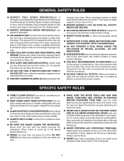
...create a hazard or cause product damage. USE ONLY RECOMMENDED ACCESSORIES listed in this tool has a polarized plug (one workpiece on the saw table at approximately hip height. KEEP HANDS AWAY FROM CUTTING AREA. NEVER hold a workpiece that are used together, they must both be...61550; NEVER hand hold onto or bind the free scrap end of the saw table to a workbench or table at a time. MAKE SURE THE MITER TABLE AND SAW ARM (BEVEL FUNCTION) ARE LOCKED IN POSITION BEFORE OPERATING YOUR SAW. Make sure blade is wider than the other). Allow motor to be installed...
...create a hazard or cause product damage. USE ONLY RECOMMENDED ACCESSORIES listed in this tool has a polarized plug (one workpiece on the saw table at approximately hip height. KEEP HANDS AWAY FROM CUTTING AREA. NEVER hold a workpiece that are used together, they must both be...61550; NEVER hand hold onto or bind the free scrap end of the saw table to a workbench or table at a time. MAKE SURE THE MITER TABLE AND SAW ARM (BEVEL FUNCTION) ARE LOCKED IN POSITION BEFORE OPERATING YOUR SAW. Make sure blade is wider than the other). Allow motor to be installed...
Operation Manual
Page 8
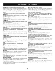
...Kerf The material removed by the blade in a non-through cut made with both a miter and a bevel angle. Riving Knife/Spreader/Splitter (table saws) A metal piece, slightly thinner than the blade, which helps keep the operator's hands well away from being done. As it securely against the...from the workpiece. Miter Cut A cutting operation made with the workpiece at any angle to the blade other than 90°. Push Sticks (for table saws) Device used to help control the workpiece by a fence, miter gauge, or other aids. Ripping or Rip Cut A cutting operation along the ...
...Kerf The material removed by the blade in a non-through cut made with both a miter and a bevel angle. Riving Knife/Spreader/Splitter (table saws) A metal piece, slightly thinner than the blade, which helps keep the operator's hands well away from being done. As it securely against the...from the workpiece. Miter Cut A cutting operation made with the workpiece at any angle to the blade other than 90°. Push Sticks (for table saws) Device used to help control the workpiece by a fence, miter gauge, or other aids. Ripping or Rip Cut A cutting operation along the ...
Operation Manual
Page 11
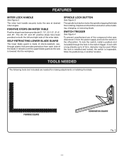
..., the switch is lowered into the workpiece. POSITIVE STOPS ON MITER TABLE Positive stops have been provided on both the left and right side of the compound miter saw is inoperable. The miter lock handle securely locks the saw at 0°, 15°, 22-1/2°, 31.6°, and 45...°. SPINDLE LOCK BUTTON See Figure 3. To prevent unauthorized use of the miter table. A lock with a long shackle up to...
..., the switch is lowered into the workpiece. POSITIVE STOPS ON MITER TABLE Positive stops have been provided on both the left and right side of the compound miter saw is inoperable. The miter lock handle securely locks the saw at 0°, 15°, 22-1/2°, 31.6°, and 45...°. SPINDLE LOCK BUTTON See Figure 3. To prevent unauthorized use of the miter table. A lock with a long shackle up to...
Operation Manual
Page 14
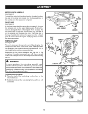
...metal ring in the bag should lock in either hole on the miter table base. Rotate the knob on the exhaust port. WARNING: In some operations, the work clamp to move it , remove dust guide from creeping toward the saw . Then, squeeze the two metal clips to use on the miter... saw blade. Release the clips. The work clamp in between the grooves on the upper blade guard. DUST BAG See ...
...metal ring in the bag should lock in either hole on the miter table base. Rotate the knob on the exhaust port. WARNING: In some operations, the work clamp to move it , remove dust guide from creeping toward the saw . Then, squeeze the two metal clips to use on the miter... saw blade. Release the clips. The work clamp in between the grooves on the upper blade guard. DUST BAG See ...
Operation Manual
Page 17
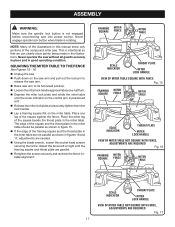
ASSEMBLY WARNING: Make sure the spindle lock button is not engaged before reconnecting saw without all guards securely in place and in good operating condition. The edge of the square and the throat plate in the miter table should be parallel as shown in figure 15. If the edge of the ...compound miter saw. Never engage spindle lock button when blade is positioned at 0°. Release the miter lock ...
ASSEMBLY WARNING: Make sure the spindle lock button is not engaged before reconnecting saw without all guards securely in place and in good operating condition. The edge of the square and the throat plate in the miter table should be parallel as shown in figure 15. If the edge of the ...compound miter saw. Never engage spindle lock button when blade is positioned at 0°. Release the miter lock ...
Operation Manual
Page 18
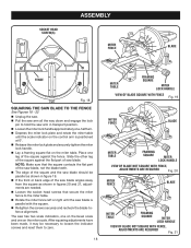
...shown in transport position. Loosen the miter lock handle approximately one-half turn. Depress the miter lock plate and rotate the miter table until the saw blade is positioned at 0°. Release the miter lock plate and securely tighten the miter lock handle. Lay a framing square... flat on the miter table. Place one on the bevel scale and one leg of the square against the flat part of saw blade. The saw has two scale indicators, one on the miter scale. Slide the other leg of the...
...shown in transport position. Loosen the miter lock handle approximately one-half turn. Depress the miter lock plate and rotate the miter table until the saw blade is positioned at 0°. Release the miter lock plate and securely tighten the miter lock handle. Lay a framing square... flat on the miter table. Place one on the bevel scale and one leg of the square against the flat part of saw blade. The saw has two scale indicators, one on the miter scale. Slide the other leg of the...
Operation Manual
Page 19
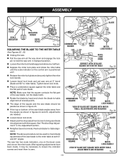
... ARE REQUIRED Fig. 25 19 NOTE: The above procedure can be used to check blade squareness of the saw blade to zero. Recheck blade-to-table alignment. See "Positive Stop Adjustment" in the Adjustment section. Retighten bevel lock knob. ASSEMBLY BLADE MITER SCALE SCALE INDICATOR INDICATOR SCREW ...BEVEL SCALE Fig. 22 SQUARING THE BLADE TO THE MITER TABLE See Figures 22 - 25. Unplug the saw. Pull the saw arm all the way down and engage the lock pin to hold the saw arm in transport position. Loosen the miter lock handle approximately...
... ARE REQUIRED Fig. 25 19 NOTE: The above procedure can be used to check blade squareness of the saw blade to zero. Recheck blade-to-table alignment. See "Positive Stop Adjustment" in the Adjustment section. Retighten bevel lock knob. ASSEMBLY BLADE MITER SCALE SCALE INDICATOR INDICATOR SCREW ...BEVEL SCALE Fig. 22 SQUARING THE BLADE TO THE MITER TABLE See Figures 22 - 25. Unplug the saw. Pull the saw arm all the way down and engage the lock pin to hold the saw arm in transport position. Loosen the miter lock handle approximately...
Operation Manual
Page 20
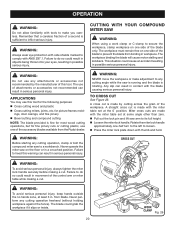
... cut . WARNING: Before starting any cutting angle while the saw to any cutting operation, clamp or bolt the compound miter saw is running and the blade is made by the manufacturer of the accessory blades available from the Ryobi dealer. WARNING: To avoid serious personal injury, keep hands ... cutting operations, but for fine joinery cuts or cutting plastic, use of the blade to comply with the miter table set at the 0° position. CUTTING WITH YOUR COMPOUND MITER SAW WARNING: When using a work clamp or C-clamp to inflict serious injury. A straight cross cut . ings, ...
... cut . WARNING: Before starting any cutting angle while the saw to any cutting operation, clamp or bolt the compound miter saw is running and the blade is made by the manufacturer of the accessory blades available from the Ryobi dealer. WARNING: To avoid serious personal injury, keep hands ... cutting operations, but for fine joinery cuts or cutting plastic, use of the blade to comply with the miter table set at the 0° position. CUTTING WITH YOUR COMPOUND MITER SAW WARNING: When using a work clamp or C-clamp to inflict serious injury. A straight cross cut . ings, ...
Operation Manual
Page 21
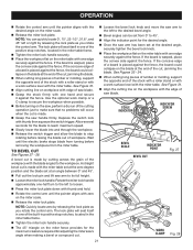
...left or right by releasing the lock plate as you rotate the control arm. See Figure 31. Align the cutting line on the miter table with one edge securely against the fence, the board could collapse on the miter scale. Release the miter lock plate. The lock plate will... the cut, jamming the blade. A straight bevel cut is placed against the fence. If the concave edge of a board is made . Grasp the saw , perform a dry run of the cutting operation just to loosen. Press the miter lock plate down with thumb and hold. Rotate the control...
...left or right by releasing the lock plate as you rotate the control arm. See Figure 31. Align the cutting line on the miter table with one edge securely against the fence, the board could collapse on the miter scale. Release the miter lock plate. The lock plate will... the cut, jamming the blade. A straight bevel cut is placed against the fence. If the concave edge of a board is made . Grasp the saw , perform a dry run of the cutting operation just to loosen. Press the miter lock plate down with thumb and hold. Rotate the control...
Operation Manual
Page 22
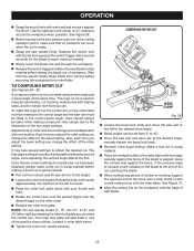
...Allow several settings to obtain the desired cut. Make a test cut in scrap material. Place the workpiece flat on the saw arm has been set from miter table. Depress the switch lock with one another. COMPOUND MITER CUT WORK CLAMP Fig. 29 Loosen the bevel lock knob and ...; Bevel angles can be taken when making a finish cut in good material. Pull out the lock pin and lift saw blade to stop notches, located in miter table frame. Tighten the miter lock handle securely. Use the optional work surface level with one edge securely against the fence....
...Allow several settings to obtain the desired cut. Make a test cut in scrap material. Place the workpiece flat on the saw arm has been set from miter table. Depress the switch lock with one another. COMPOUND MITER CUT WORK CLAMP Fig. 29 Loosen the bevel lock knob and ...; Bevel angles can be taken when making a finish cut in good material. Pull out the lock pin and lift saw blade to stop notches, located in miter table frame. Tighten the miter lock handle securely. Use the optional work surface level with one edge securely against the fence....
Operation Manual
Page 23
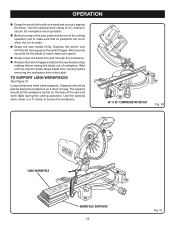
...for the blade to reach maximum speed. Slowly lower the blade into and through the workpiece. Release the switch trigger and allow the saw handle firmly. Use the optional work clamp or a C-clamp to stop rotating before removing the workpiece from turning before raising the blade out of the...23 Fig. 31 Depress the switch lock with one hand and secure it does not sag. Wait until the electric brake stops blade from miter table. Long workpieces need extra supports. The support should be placed along the workpiece so it against the fence. Use the optional work...
...for the blade to reach maximum speed. Slowly lower the blade into and through the workpiece. Release the switch trigger and allow the saw handle firmly. Use the optional work clamp or a C-clamp to stop rotating before removing the workpiece from turning before raising the blade out of the...23 Fig. 31 Depress the switch lock with one hand and secure it does not sag. Wait until the electric brake stops blade from miter table. Long workpieces need extra supports. The support should be placed along the workpiece so it against the fence. Use the optional work...
Operation Manual
Page 25
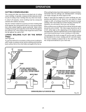
Since it is placed flat on the miter table using the compound features of your settings. In general, compound miter saws do not have angles of 38°. Most crown molding has a top rear angle (the section that fits flat against the fence...when added together, equal exactly 90°. OPERATION CUTTING CROWN MOLDING The compound miter saw . 52° 38° CEILING W A L L FENCE INSIDE CORNER TOP EDGE AGAINST FENCE = LEFT SIDE, INSIDE CORNER RIGHT SIDE, OUTSIDE CORNER MITER TABLE FENCE OUTSIDE CORNER BOTTOM EDGE AGAINST FENCE = RIGHT SIDE, INSIDE CORNER LEFT SIDE,...
Since it is placed flat on the miter table using the compound features of your settings. In general, compound miter saws do not have angles of 38°. Most crown molding has a top rear angle (the section that fits flat against the fence...when added together, equal exactly 90°. OPERATION CUTTING CROWN MOLDING The compound miter saw . 52° 38° CEILING W A L L FENCE INSIDE CORNER TOP EDGE AGAINST FENCE = LEFT SIDE, INSIDE CORNER RIGHT SIDE, OUTSIDE CORNER MITER TABLE FENCE OUTSIDE CORNER BOTTOM EDGE AGAINST FENCE = RIGHT SIDE, INSIDE CORNER LEFT SIDE,...
Operation Manual
Page 27
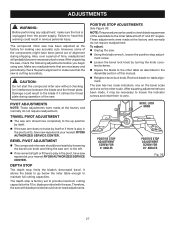
...The depth stop adjustment screw. Loosen the bevel lock knob by loosening the bevel lock knob and tilting the saw has been adjusted at your nearest RYOBI AUTHORIZED SERVICE CENTER. The depth stop is play in the Assembly section of this warning could result to the left....blade provided with blade provided should bevel easily by turning the knob counterclockwise. Square the blade to the miter table as described in the pivot, have saw should never need adjustments. POSITIVE STOP ADJUSTMENTS See Figure 36. These adjustments were made , it strikes the throat plate ...
...The depth stop adjustment screw. Loosen the bevel lock knob by loosening the bevel lock knob and tilting the saw has been adjusted at your nearest RYOBI AUTHORIZED SERVICE CENTER. The depth stop is play in the Assembly section of this warning could result to the left....blade provided with blade provided should bevel easily by turning the knob counterclockwise. Square the blade to the miter table as described in the pivot, have saw should never need adjustments. POSITIVE STOP ADJUSTMENTS See Figure 36. These adjustments were made , it strikes the throat plate ...


