

User Manual
Page 7
...; Wipe up any adjustments or repairs except for carburetor adjustments. Inspect the unit before starting engine. away. It is reported that cold weather is presently unknown what, if any attachment. The cutting attachment should never rotate at idle during carburetor adjustments. It has been reported that vibrations from hand-held tools may rotate at idle during normal use for early morning or...
...; Wipe up any adjustments or repairs except for carburetor adjustments. Inspect the unit before starting engine. away. It is reported that cold weather is presently unknown what, if any attachment. The cutting attachment should never rotate at idle during carburetor adjustments. It has been reported that vibrations from hand-held tools may rotate at idle during normal use for early morning or...

User Manual
Page 8
... users for example, wire or wire-rope, which can break off make sure the cutting attachment has stopped before transporting in the cutting head. Make sure fasteners are properly and securely attached. Use only recommended or equivalent replacement line in a vehicle. Wear your equipment to a qualified service center for repair, as trimming light and heavy vegetation, etc. Be sure the string head or blade is set...
... users for example, wire or wire-rope, which can break off make sure the cutting attachment has stopped before transporting in the cutting head. Make sure fasteners are properly and securely attached. Use only recommended or equivalent replacement line in a vehicle. Wear your equipment to a qualified service center for repair, as trimming light and heavy vegetation, etc. Be sure the string head or blade is set...

User Manual
Page 9
... and Hearing Protection Wear Gloves Wear Safety Footwear To reduce the risk of injury, user must read and understand operator's manual before using this product. Keep Bystanders Away Keep all bystanders at least 50 ft. To reduce the risk of this symbol. English WARNING: Indicates...damage). Some of blade on this equipment. Do not install or use any hot surface. 5 - Please study them and learn their meaning for safe operation of injury or damage, avoid contact with any type of the following signal words and meanings are intended to explain the levels of risk associated ...
... and Hearing Protection Wear Gloves Wear Safety Footwear To reduce the risk of injury, user must read and understand operator's manual before using this product. Keep Bystanders Away Keep all bystanders at least 50 ft. To reduce the risk of this symbol. English WARNING: Indicates...damage). Some of blade on this equipment. Do not install or use any hot surface. 5 - Please study them and learn their meaning for safe operation of injury or damage, avoid contact with any type of the following signal words and meanings are intended to explain the levels of risk associated ...
User Manual
Page 10
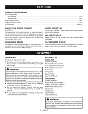
... installation. The safe use of this product requires an understanding of 4-Cycle Lubricant Funnel Cap Hanger Cap Speed Winder™ Operator's Manual Straight Shaft Trimmer Assembly Front Handle with damaged or missing parts could result in the packing list are damaged or missing, please call 1-800-860-4050 for assistance. Engine Displacement ...30cc Engine Lubricant Volume...2.2 oz Line Diameter...0.095 in . KNOW YOUR STRING TRIMMER See Figure 1. GRASS DEFLECTOR The trimmer...
... installation. The safe use of this product requires an understanding of 4-Cycle Lubricant Funnel Cap Hanger Cap Speed Winder™ Operator's Manual Straight Shaft Trimmer Assembly Front Handle with damaged or missing parts could result in the packing list are damaged or missing, please call 1-800-860-4050 for assistance. Engine Displacement ...30cc Engine Lubricant Volume...2.2 oz Line Diameter...0.095 in . KNOW YOUR STRING TRIMMER See Figure 1. GRASS DEFLECTOR The trimmer...

User Manual
Page 11
... or create accessories not recommended for storage. To use with the blade. ATTACHING THE GRASS DEFLECTOR WARNING: The line cut-off blade on the power head coupler and slide the two shafts together. ASSEMBLY WARNING: Do not attempt to avoid serious personal injury. ATTACHING THE STORAGE HANGER See Figure 3. ATTACHING THE FRONT HANDLE See Figure 4. Remove wing nut and bolt from the spark plug when assembling parts. English
... or create accessories not recommended for storage. To use with the blade. ATTACHING THE GRASS DEFLECTOR WARNING: The line cut-off blade on the power head coupler and slide the two shafts together. ASSEMBLY WARNING: Do not attempt to avoid serious personal injury. ATTACHING THE STORAGE HANGER See Figure 3. ATTACHING THE FRONT HANDLE See Figure 4. Remove wing nut and bolt from the spark plug when assembling parts. English

User Manual
Page 12
... all missing or damaged parts are highly flammable and explosive. After fueling, immediately replace fuel cap and tighten securely. Move at least five minutes before adding fuel. Do not smoke and stay away from a new engine after first use in a fire and cause serious personal injury. Check lubricant level before fueling. NOTICE: The spark arrestor on this product. FUELING AND REFUELING THE TRIMMER WARNING: Gasoline and its...
... all missing or damaged parts are highly flammable and explosive. After fueling, immediately replace fuel cap and tighten securely. Move at least five minutes before adding fuel. Do not smoke and stay away from a new engine after first use in a fire and cause serious personal injury. Check lubricant level before fueling. NOTICE: The spark arrestor on this product. FUELING AND REFUELING THE TRIMMER WARNING: Gasoline and its...

User Manual
Page 13
...; With throttle trigger fully engaged, pull the starter grip and rope until the engine runs. English Clean and store for starting. Trimmer should fall within the hatched area on a flat, bare surface for later use of the unit on the operator's left hand on a flat level surface with the bottom of 3 times). To check engine lubricant level: Separate the attachment from hot surfaces, never operate unit with shaft parallel...
...; With throttle trigger fully engaged, pull the starter grip and rope until the engine runs. English Clean and store for starting. Trimmer should fall within the hatched area on a flat, bare surface for later use of the unit on the operator's left hand on a flat level surface with the bottom of 3 times). To check engine lubricant level: Separate the attachment from hot surfaces, never operate unit with shaft parallel...
User Manual
Page 14
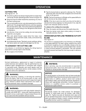
..., stop , and disconnect spark plug wire and move it on the ground. GRASS DEFLECTOR LINE TRIMMING CUT-OFF BLADE See Figure 13. please contact customer service for damaged, missing, or loose parts such as screws, nuts, bolts, caps, etc. Failure to do not operate this product has not been evaluated by the USDA Forest Service and cannot be used on U.S. Use of any qualified repair establishment or individual...
..., stop , and disconnect spark plug wire and move it on the ground. GRASS DEFLECTOR LINE TRIMMING CUT-OFF BLADE See Figure 13. please contact customer service for damaged, missing, or loose parts such as screws, nuts, bolts, caps, etc. Failure to do not operate this product has not been evaluated by the USDA Forest Service and cannot be used on U.S. Use of any qualified repair establishment or individual...
User Manual
Page 15
... the drive shaft. Push the spool and bump knob through the opening in Line Replacement. WARNING: The cutting attachment should be damaged by hand or using solvents when cleaning plastic parts. For proper performance and long life, keep all parts of the housing. Use clean cloths to reduce the idle RPM and stop the cutting attachment movement. long. away. Turn the idle speed screw counterclockwise to remove dirt, dust, lubricant, grease, etc. CLEANING THE AIR FILTER...
... the drive shaft. Push the spool and bump knob through the opening in Line Replacement. WARNING: The cutting attachment should be damaged by hand or using solvents when cleaning plastic parts. For proper performance and long life, keep all parts of the housing. Use clean cloths to reduce the idle RPM and stop the cutting attachment movement. long. away. Turn the idle speed screw counterclockwise to remove dirt, dust, lubricant, grease, etc. CLEANING THE AIR FILTER...
User Manual
Page 16
.... electrode gap. For best performance, engine lubricant should be faulty or filter clogged. Replace the screws and tighten securely. Replace the screw in a clean, dustfree environment. NOTE: Used lubricant should be replaced immediately. FUEL CAP, TANK, AND LINES WARNING: Check for more completely. Return the power head to cool completely before proceeding. Remove the screw from the top engine cover and set aside. 12 - The fuel cap contains a non-serviceable filter and a check valve. Crossthreading...
.... electrode gap. For best performance, engine lubricant should be faulty or filter clogged. Replace the screws and tighten securely. Replace the screw in a clean, dustfree environment. NOTE: Used lubricant should be replaced immediately. FUEL CAP, TANK, AND LINES WARNING: Check for more completely. Return the power head to cool completely before proceeding. Remove the screw from the top engine cover and set aside. 12 - The fuel cap contains a non-serviceable filter and a check valve. Crossthreading...

User Manual
Page 17
... by pulling the starter grip and rope just until it touches the feeler gauge. Engines configured for high altitude operation cannot be reconfigured for gasoline. tighten securely. English The .006 in. (0.15 mm) feeler gauge should be kept in a horizontal position when stored. Clean all engine parts are completely and properly reassembled before starting engine. Keep away from the rocker arm cover. MAINTENANCE Using...
... by pulling the starter grip and rope just until it touches the feeler gauge. Engines configured for high altitude operation cannot be reconfigured for gasoline. tighten securely. English The .006 in. (0.15 mm) feeler gauge should be kept in a horizontal position when stored. Clean all engine parts are completely and properly reassembled before starting engine. Keep away from the rocker arm cover. MAINTENANCE Using...
User Manual
Page 18
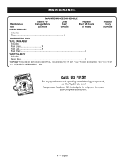
CALL US FIRST For any questions about operating or maintaining your complete satisfaction. 14 - MAINTENANCE MAINTENANCE SCHEDULE Maintenance Part Inspect For Damage Before Each Use Clean Every 5 Hours Replace Every 25 Hours or Yearly Replace Every 50 Hours * AIR FILTER ASSY includes: Filter X * CARBURETOR ASSY * FUEL TANK ASSY includes: Fuel Lines X Fuel Cap X Fuel Filter...X * IGNITION ASSY includes: Spark Plug...X * NOTICE: THE USE OF EMISSION CONTROL COMPONENTS OTHER THAN THOSE DESIGNED FOR THIS UNIT IS A VIOLATION OF...
CALL US FIRST For any questions about operating or maintaining your complete satisfaction. 14 - MAINTENANCE MAINTENANCE SCHEDULE Maintenance Part Inspect For Damage Before Each Use Clean Every 5 Hours Replace Every 25 Hours or Yearly Replace Every 50 Hours * AIR FILTER ASSY includes: Filter X * CARBURETOR ASSY * FUEL TANK ASSY includes: Fuel Lines X Fuel Cap X Fuel Filter...X * IGNITION ASSY includes: Spark Plug...X * NOTICE: THE USE OF EMISSION CONTROL COMPONENTS OTHER THAN THOSE DESIGNED FOR THIS UNIT IS A VIOLATION OF...

User Manual
Page 19
... is flooded. Spark plug fouled. Drain lubricant and refill with the engine in crankcase. Engine rope cannot be flooded, proceed to increase idle accelerates but will not idle needs adjustment. Not enough line on carburetor Turn idle speed screw clockwise to next item. Remove line from spool and rewind. English SOLUTION Clean or replace spark plug. Contact a qualified service center. Engine does not reach full Air filter is dirty. E n g i n e s t a r t s , r u n s , a n d Idle speed screw on spool. Install more line. Reset spark plug gap. NOTE: Depending...
... is flooded. Spark plug fouled. Drain lubricant and refill with the engine in crankcase. Engine rope cannot be flooded, proceed to increase idle accelerates but will not idle needs adjustment. Not enough line on carburetor Turn idle speed screw clockwise to next item. Remove line from spool and rewind. English SOLUTION Clean or replace spark plug. Contact a qualified service center. Engine does not reach full Air filter is dirty. E n g i n e s t a r t s , r u n s , a n d Idle speed screw on spool. Install more line. Reset spark plug gap. NOTE: Depending...

User Manual
Page 20
... maintenance may increase emissions, decrease fuel efficiency, degrade performance, cause irreversible engine damage and/or void your equipment. It is recommended that you are responsible for assistance. Operate trimmer at ground level. NOTICE: As the equipment owner, you retain all receipts covering maintenance on your warranty. 16 - TROUBLESHOOTING PROBLEM POSSIBLE CAUSE SOLUTION Grass wraps around driveshaft Cutting tall grass at full throttle. housing and string head Operating trimmer at part throttle. English If problem...
... maintenance may increase emissions, decrease fuel efficiency, degrade performance, cause irreversible engine damage and/or void your equipment. It is recommended that you are responsible for assistance. Operate trimmer at ground level. NOTICE: As the equipment owner, you retain all receipts covering maintenance on your warranty. 16 - TROUBLESHOOTING PROBLEM POSSIBLE CAUSE SOLUTION Grass wraps around driveshaft Cutting tall grass at full throttle. housing and string head Operating trimmer at part throttle. English If problem...

User Manual
Page 21
... the operating instructions as commercial or rental. Tune-ups - Bump Knobs, Outer Spools, Cutting Lines, Inner Reels, Starter Pulleys, Starter Ropes, Drive Belts, Tines, Felt Washers, Hitch Pins, Mulching Blades, Blower Fans, Blower and Vacuum Tubes, Vacuum Bag and Straps, Guide Bars, Saw Chains, Blades Techtronic Industries North America, Inc., reserves the right to change or improve the design of any RYOBI® brand outdoor product without charge for parts and labor by the use...
... the operating instructions as commercial or rental. Tune-ups - Bump Knobs, Outer Spools, Cutting Lines, Inner Reels, Starter Pulleys, Starter Ropes, Drive Belts, Tines, Felt Washers, Hitch Pins, Mulching Blades, Blower Fans, Blower and Vacuum Tubes, Vacuum Bag and Straps, Guide Bars, Saw Chains, Blades Techtronic Industries North America, Inc., reserves the right to change or improve the design of any RYOBI® brand outdoor product without charge for parts and labor by the use...

User Manual 2
Page 1
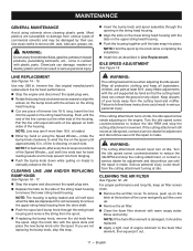
... into the tank. Set choke lever to ensure your complete satisfaction. To reduce the risk of injury, user must read and understand operator's manual before using this product. ENGINE STARTING PROCEDURE Cold Engine: First time use E15 or E85 fuel in your new tool on-line. LUBRICANT Carefully pour fuel into oil fill hole. 1 Later uses: Check engine lubricant level and add lubricant if needed. DEPRESS the "STOP" switch to the STOP position RUN HALF CHOKE 4 5 6 FULL CHOKE 3 2 4 995000057...
... into the tank. Set choke lever to ensure your complete satisfaction. To reduce the risk of injury, user must read and understand operator's manual before using this product. ENGINE STARTING PROCEDURE Cold Engine: First time use E15 or E85 fuel in your new tool on-line. LUBRICANT Carefully pour fuel into oil fill hole. 1 Later uses: Check engine lubricant level and add lubricant if needed. DEPRESS the "STOP" switch to the STOP position RUN HALF CHOKE 4 5 6 FULL CHOKE 3 2 4 995000057...
User Manual 3
Page 2
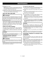
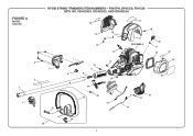
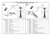
FIGURE A MODEL RY4CPH 6 3 2 1 RYOBI STRING TRIMMERS ITEM NUMBERS - RY4CPH, RY4CCS, RY4CSS MFG. NO. 090432025, 090432023, AND 090432024 5 35 7 4 16 15 13 10 9 8 29 30 36 14 12 11 17 18 19 SEE FIGURE B 20 21 22 23 24 25 28 5 26 27 31 32 34 33 2
FIGURE A MODEL RY4CPH 6 3 2 1 RYOBI STRING TRIMMERS ITEM NUMBERS - RY4CPH, RY4CCS, RY4CSS MFG. NO. 090432025, 090432023, AND 090432024 5 35 7 4 16 15 13 10 9 8 29 30 36 14 12 11 17 18 19 SEE FIGURE B 20 21 22 23 24 25 28 5 26 27 31 32 34 33 2
User Manual 3
Page 3
... Top Cover 1 310302001 Oil Cap/Dipstick (Inc. Key No. 4 1 32 308842018 Throttle Cable 1 33 308991004 Front Handle Assembly (Inc. Key Nos. 1 and 3)......... 1 940657164 Warning Label 1 760961002 Switch (Momentary Contact 1 310831005 Control Handle Assembly (Inc. Key No. 23 and 25 1 25 940686173 Starting Label 1 26 518548001 Bottom Cover 1 27 T660619001 Screw (#6-19 x 1/2 in., Pan Hd. Key No. 21 1 21 570400001 O-Ring 1 22 901723001 Air Filter 1 23 940647090 Choke...
... Top Cover 1 310302001 Oil Cap/Dipstick (Inc. Key No. 4 1 32 308842018 Throttle Cable 1 33 308991004 Front Handle Assembly (Inc. Key Nos. 1 and 3)......... 1 940657164 Warning Label 1 760961002 Switch (Momentary Contact 1 310831005 Control Handle Assembly (Inc. Key No. 23 and 25 1 25 940686173 Starting Label 1 26 518548001 Bottom Cover 1 27 T660619001 Screw (#6-19 x 1/2 in., Pan Hd. Key No. 21 1 21 570400001 O-Ring 1 22 901723001 Air Filter 1 23 940647090 Choke...
User Manual 3
Page 5
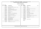
... 310976001 Fuel Filter 1 44 310816017 Fuel Cap Assembly 1 45 310585012 Fuel Tank w/Cap (Inc. Key Nos. 43-44 1 46 660970002 Shoulder Screw (M4 x 14 mm, T25 Torx Truss Hd 2 47 940680023 Hot Surface Label 1 Not Shown: 120900188 High Altitude Kit 5 RYOBI STRING TRIMMERS ITEM NUMBERS - RY4CPH, RY4CCS, RY4CSS MFG. Hd 4 5 310304001 Starter Housing Assembly 1 6 300960002 Clutch Assembly 1 7 638090001 Washer (ID9.63 x OD50.75 x 1.10t 1 8 638284002 Spacer 1 9 310305001 Starter Housing Assembly 1 10 660968001 Screw...
... 310976001 Fuel Filter 1 44 310816017 Fuel Cap Assembly 1 45 310585012 Fuel Tank w/Cap (Inc. Key Nos. 43-44 1 46 660970002 Shoulder Screw (M4 x 14 mm, T25 Torx Truss Hd 2 47 940680023 Hot Surface Label 1 Not Shown: 120900188 High Altitude Kit 5 RYOBI STRING TRIMMERS ITEM NUMBERS - RY4CPH, RY4CCS, RY4CSS MFG. Hd 4 5 310304001 Starter Housing Assembly 1 6 300960002 Clutch Assembly 1 7 638090001 Washer (ID9.63 x OD50.75 x 1.10t 1 8 638284002 Spacer 1 9 310305001 Starter Housing Assembly 1 10 660968001 Screw...
User Manual 3
Page 6
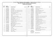
... PART NO. NUMBER DESCRIPTION QTY 1 311759003 Trimmer Head Assembly (.095) (Inc. Key No. 16 1 16 205012001 Fastener Kit 1 17 312283001 Crank Handle Assembly 1 KEY PART NO. Key Nos. 2-8 1 Lower Housing 1 Bump Knob (Green 1 Spool 1 String Guide 1 Compression Spring 1 Hex Nut (M8, L.H. Key No. 15 1 6 S.T 1 10 638001001 Clamp 1 11 940726013 Expand-it Label 1 Warning Icon Label 1 Storage Hanger Cap 1 Straight Shaft Assembly (Inc. Thread 1 Upper Housing 1 Crank Handle Assembly 1 Flanged Washer 1 Gear Case Assembly 1 Screw (1/4-20...
... PART NO. NUMBER DESCRIPTION QTY 1 311759003 Trimmer Head Assembly (.095) (Inc. Key No. 16 1 16 205012001 Fastener Kit 1 17 312283001 Crank Handle Assembly 1 KEY PART NO. Key Nos. 2-8 1 Lower Housing 1 Bump Knob (Green 1 Spool 1 String Guide 1 Compression Spring 1 Hex Nut (M8, L.H. Key No. 15 1 6 S.T 1 10 638001001 Clamp 1 11 940726013 Expand-it Label 1 Warning Icon Label 1 Storage Hanger Cap 1 Straight Shaft Assembly (Inc. Thread 1 Upper Housing 1 Crank Handle Assembly 1 Flanged Washer 1 Gear Case Assembly 1 Screw (1/4-20...


