Ryobi P20101BTL Support and Manuals
Get Help and Manuals for this Ryobi item

View All Support Options Below
Free Ryobi P20101BTL manuals!
Problems with Ryobi P20101BTL?
Ask a Question
Free Ryobi P20101BTL manuals!
Problems with Ryobi P20101BTL?
Ask a Question
Ryobi P20101BTL Videos

Ryobi One+ 18-Volt Lithium-Ion Cordless Attachment Capable Brushless String Trimmer P20101BTL
Duration: 5:44
Total Views: 19,006
Duration: 5:44
Total Views: 19,006
2020-06-04 New replacement Ryobi P20101BTL
Duration: :43
Total Views: 270
Duration: :43
Total Views: 270
Popular Ryobi P20101BTL Manual Pages
Operation Manual - Page 4

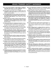
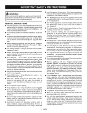
...SPECIFIC SAFETY RULES
Replace string head if cracked, chipped, or damaged in . Read and understand the operator's manual and observe the warnings and instruction... tired or under any a djustments or repairs except for carburetor adjustments.
... injury.
Use only original manufacturer's replacement parts.
If you are properly and securely attached.
...
Operation Manual - Page 5
... . Before you off balance.
This reduces the risk of injury from moving blade. Incorrect replacement parts may strike the operator and/or throw the machine out of injury from your footing, always... clearing jammed material or servicing may cause a loss of balance or control of the machine "live" and could give the operator an electric shock.
n Follow instructions for wildlife where the...
Operation Manual - Page 9
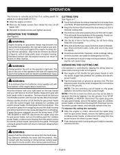
...rear handle and your arm, hand, or any body part against the engine housing during trimmer operation. Prolonged cutting...trees and shrubs. do the cutting; To advance the cutting line manually: Stop the engine or motor, disconnect the spark plug... passing the unit from overheating. OPERATION
This trimmer is currently set at the 13 in operation.
WARNING:
To avoid burns from...
Operation Manual - Page 10
... side shields marked to manually advance the line. NOTE...servicing the machine, shut off engine or motor, wait for all missing or damaged parts are replaced...Install line as screws, nuts, bolts, caps, etc.
long. NOTE: Line may be used for hanging purposes as well.
8 -
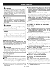
Align the knob ribs with ANSI Z87.1. LINE REPLACEMENT...necessary to follow these instructions can result in the...
Operation Manual - Page 11

... prior to shipment to Line Replacement earlier in this manual.
Install more line. Pull lines while alternately pressing down to Line Replacement earlier in this manual. Refer to prevent wrapping.
...well-ventilated place that is tangled on spool.
REPLACEMENT PARTS
0.080 in. Cutting tall grass at homedepot.com
TROUBLESHOOTING
PROBLEM
Line will not advance
Grass wraps around boom ...
Parts Diagram - Page 2
Key Nos. 3-5, RY15527)
1
2
316008001
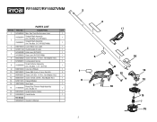
Straight Shaft Assembly (Inc. RY15527/RY15527VNM
PARTS LIST
KEY NO. Key Nos. 3-5, RY15527VNM)
1
3 940749034 Lower Boom Icon Label
1
4 ...16 638125001 Grass Deflector Clamp
1
17 532048003 Crank Handle
1
Not Shown:
995000976 Operator's Manual
2
4 17
5 1
8 9
2
3
16 6
14 12 11
13 10
15 7
15 PART NO. DESCRIPTION
QTY.
1 941588552 Max.
Operation Manual - Page 4
... risk of footwear and gloves with grounded surfaces such as indicated in the instructions for use . Use of serious personal injury.
Use Safety Glasses - Footwear should be properly repaired or replaced by an authorized service center unless indicated elsewhere in this manual.
Keep hands and feet away from any job except that it...
Operation Manual - Page 5

...; Keep all charging instructions and do not expose the product to instruct others who may overheat and cause burns.
Follow all parts of the body away...use in areas where they are moving parts come to a complete stop, and remove the battery pack before servicing, cleaning or removing material from the saw...SPECIFIC SAFETY RULES CAN BE FOUND IN THE APPLICABLE ATTACHMENT'S OPERATOR...
Operation Manual - Page 6

...No Blade
Recycle Symbol
Direct Current No Load Speed Per Minute Volts Hertz Minutes
Do not install or use any type of blade on this symbol. Ricochet
Thrown objects can ricochet and .... SYMBOLS
The following symbols may be used on a product displaying this product. Read Operator's Manual
To reduce the risk of the following signal words and meanings are intended to operate the product...
Operation Manual - Page 7

... used with all warnings and instructions. FEATURES
KNOW YOUR POWER HEAD
See Figure 1. INSTALLING AN ATTACHMENT TO THE POWER HEAD
See Figure 2.
Using low speed during shipping.
ASSEMBLY
UNPACKING
This product requires assembly. n Carefully remove the product and any parts are damaged or missing do not operate this Operator's Manual. PACKING LIST
Power Head...
Operation Manual - Page 8
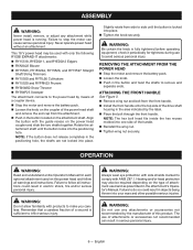
...Failure to follow all instructions could result in the attachment's Operator's Manual. ATTACHING THE FRONT HANDLE
See Figure 3. Remove wing nut and bolt from the front handle. Install the front handle onto ... ends. OPERATION
WARNING:
Read and understand entire Operator's Manual for tightness during use of attachment used with the guide recess on this product.
Operation Manual - Page 9
...instructions, refer to the Operator's Manuals for your specific...charger models....instructions in objects being thrown into the product as prescribed in serious personal injury. WARNING:
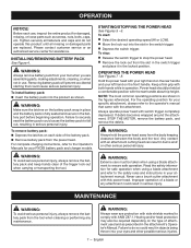
Always hold the power head away from the power head. OPERATING THE POWER HEAD
See Figures 7 - 8. Please contact customer service or an authorized service center for damaged, missing, or loose parts...INSTALLING...
Operation Manual - Page 10

... is not secure.
TROUBLESHOOTING
PROBLEM
POSSIBLE CAUSE
Motor fails to remove dirt, dust, oil, grease, etc. SOLUTION
To secure the battery pack, make sure the latch on the plastic housing or the handle. Charge the battery pack according to the instructions included with plastic parts. English WARNING:
When servicing, use only identical replacement parts.
WARNING:
Do not...
Parts Diagram - Page 1

..., Anderson, SC 29622 1-800-525-2579 www.ryobitools.com
The model number and manufacturing location will be found on a label attached to the product. Always mention this information in all communications regarding this product and when ordering parts.
11-22-21 (Rev:06) P20104 315286001
P20104VNM 315286101
DESCRIPTION
18 Volt...
Parts Diagram - Page 3

...
16
1
316009001 Boom Assembly (Inc.
P20104/P20104VNM
KEY NO. 1 2 3 4 5 6 7 8 9 10
11 12
PART NO. 315989001 940705585 661864007 660203052 313244003 292194001 315990001 760649001 539255001 314833001 315386001 308991003
DESCRIPTION Rear Handle Assembly (Inc. Key Nos. 18-20,...
1
20 941588795 Warning Icons Label
1
1
Not Shown:
1
995000973 Operator's Manual
3 PART NO. Key Nos. 14-15...
Ryobi P20101BTL Reviews
We have not received any reviews for Ryobi yet.