

Operation Manual
Page 4
... trimmer attachment. Do not use in the operator's manual. Avoid dangerous environments. Be sure the string head is intended. or more above shoulder level to prevent entanglement in any moving part. Do not touch areas around the muffler or cylinder of inattention while operating power tools may use this product in rain. Use the right attachment. Remove all bystanders, children, and pets at all instructions listed...
... trimmer attachment. Do not use in the operator's manual. Avoid dangerous environments. Be sure the string head is intended. or more above shoulder level to prevent entanglement in any moving part. Do not touch areas around the muffler or cylinder of inattention while operating power tools may use this product in rain. Use the right attachment. Remove all bystanders, children, and pets at all instructions listed...

Operation Manual
Page 5
... parts. Unexpected actuation of injury. GRASS TRIMMER SAFETY WARNINGS n Do not use the machine in bad weather conditions, especially when there is released, the brush or sapling may strike the operator and/or throw the machine out of control. Thrown objects can result in injury to be used . Improperly tightened blade securing nuts or bolts may make sure the cutting line or blade is removed...
... parts. Unexpected actuation of injury. GRASS TRIMMER SAFETY WARNINGS n Do not use the machine in bad weather conditions, especially when there is released, the brush or sapling may strike the operator and/or throw the machine out of control. Thrown objects can result in injury to be used . Improperly tightened blade securing nuts or bolts may make sure the cutting line or blade is removed...

Operation Manual
Page 6
... and meanings are intended to explain the levels of risk associated with hearing protection when operating this equipment. Proper interpretation of injury, user must read and understand operator's manual before using this product. SYMBOL NAME EXPLANATION Safety Alert Symbol Indicates a potential personal injury hazard. Do not install or use any type of blade on this product. CAUTION: Indicates a hazardous situation...
... and meanings are intended to explain the levels of risk associated with hearing protection when operating this equipment. Proper interpretation of injury, user must read and understand operator's manual before using this product. SYMBOL NAME EXPLANATION Safety Alert Symbol Indicates a potential personal injury hazard. Do not install or use any type of blade on this product. CAUTION: Indicates a hazardous situation...

Operation Manual
Page 7
... Straight Shaft Trimmer Attachment SPEED WINDER™ 0.080 in . Spiral Replacement Line Grass Deflector Operator's Manual WARNING: If any parts in this operator's manual as well as a knowledge of this product, familiarize yourself with this product until the parts are damaged or missing, please call 1-800-525-2579 for string trimming when using spooled replacement line. WARNING: Do not connect to possible serious personal injury. FEATURES PRODUCT SPECIFICATIONS Line Cutting Width...
... Straight Shaft Trimmer Attachment SPEED WINDER™ 0.080 in . Spiral Replacement Line Grass Deflector Operator's Manual WARNING: If any parts in this operator's manual as well as a knowledge of this product, familiarize yourself with this product until the parts are damaged or missing, please call 1-800-525-2579 for string trimming when using spooled replacement line. WARNING: Do not connect to possible serious personal injury. FEATURES PRODUCT SPECIFICATIONS Line Cutting Width...

Operation Manual
Page 8
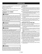
... customer service or a qualified service center for the purpose listed below: Trimming grass and weeds from side to stop the engine or motor may use blades, flailing devices, wire, or rope on the power head coupler and slide the two shafts together. Failure to side until it periodically for damaged, missing, or loose parts such as screws, nuts, bolts, caps, etc. Align the button with trimmer line LINE TRIMMING CUT-OFF BLADE See...
... customer service or a qualified service center for the purpose listed below: Trimming grass and weeds from side to stop the engine or motor may use blades, flailing devices, wire, or rope on the power head coupler and slide the two shafts together. Failure to side until it periodically for damaged, missing, or loose parts such as screws, nuts, bolts, caps, etc. Align the button with trimmer line LINE TRIMMING CUT-OFF BLADE See...
Operation Manual
Page 9
... grass from wrapping around the string head, STOP THE ENGINE or MOTOR, disconnect the spark plug wire for gas power heads, remove the battery pack for cordless power heads, or disconnect the plug from the muffler. This will result in lubricant dripping from the power source for electric power heads, and manually advance the line. Prolonged cutting at the operator. This will cut -off blade 180°. Reinstall the blade screws and tighten securely. NOTE: The line trimming cut the line...
... grass from wrapping around the string head, STOP THE ENGINE or MOTOR, disconnect the spark plug wire for gas power heads, remove the battery pack for cordless power heads, or disconnect the plug from the muffler. This will result in lubricant dripping from the power source for electric power heads, and manually advance the line. Prolonged cutting at the operator. This will cut -off blade 180°. Reinstall the blade screws and tighten securely. NOTE: The line trimming cut the line...
Operation Manual
Page 10
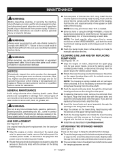
.... Use original manufacturer's replacement line for best performance. Stop the engine or motor, disconnect the spark plug wire for gas power heads, remove the battery pack for cordless power heads, or disconnect the plug from the power source for electric power heads. Rotate the lower housing counterclockwise so the arrow on the upper housing aligns with the lock on the spool until the button locks into place. The secondary hole in the attachment shaft...
.... Use original manufacturer's replacement line for best performance. Stop the engine or motor, disconnect the spark plug wire for gas power heads, remove the battery pack for cordless power heads, or disconnect the plug from the power source for electric power heads. Rotate the lower housing counterclockwise so the arrow on the upper housing aligns with the lock on the spool until the button locks into place. The secondary hole in the attachment shaft...
Operation Manual
Page 11
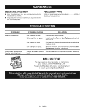
Line is tangled on spool. Refer to Line Replacement earlier in this manual. Cut tall grass from the top down on and releasing bump knob. For warranty details, visit www.ryobitools.com or call the RYOBI Help Line! Cutting tall grass at homedepot.com TROUBLESHOOTING PROBLEM Line will not advance Grass wraps around boom housing and string head POSSIBLE CAUSE Line is welded to itself. Remove line from corrosive agents such as garden chemicals...
Line is tangled on spool. Refer to Line Replacement earlier in this manual. Cut tall grass from the top down on and releasing bump knob. For warranty details, visit www.ryobitools.com or call the RYOBI Help Line! Cutting tall grass at homedepot.com TROUBLESHOOTING PROBLEM Line will not advance Grass wraps around boom housing and string head POSSIBLE CAUSE Line is welded to itself. Remove line from corrosive agents such as garden chemicals...

Parts Diagram
Page 1
REPAIR SHEET BRAND RYOBI MODEL NO. Box 1288, Anderson, SC 29622 1-800-525-2579 www.ryobitools.com The model number and manufacturing location will be found on a label attached to the product. NO. P.O. Always mention this information in all communications regarding this product and when ordering parts. 7-5-22 (Rev:08) RY15527 311247006 RY15527VNM 311247106 DESCRIPTION EXPAND-IT Straight Shaft Trimmer Attachment TTI OUTDOOR POWER EQUIPMENT, INC. MFG.
REPAIR SHEET BRAND RYOBI MODEL NO. Box 1288, Anderson, SC 29622 1-800-525-2579 www.ryobitools.com The model number and manufacturing location will be found on a label attached to the product. NO. P.O. Always mention this information in all communications regarding this product and when ordering parts. 7-5-22 (Rev:08) RY15527 311247006 RY15527VNM 311247106 DESCRIPTION EXPAND-IT Straight Shaft Trimmer Attachment TTI OUTDOOR POWER EQUIPMENT, INC. MFG.
Parts Diagram
Page 2
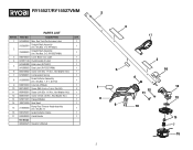
... Flanged Washer 1 14 308210009 Gear Head 1 15 314608005 Bump Feed Trimmer Head Assembly (Inc. Run Time/Performance Label 1 315992001 Straight Shaft Assembly (Inc. Key No. 7) 1 16 638125001 Grass Deflector Clamp 1 17 532048003 Crank Handle 1 Not Shown: 995000976 Operator's Manual 2 4 17 5 1 8 9 2 3 16 6 14 12 11 13 10 15 7 15 DESCRIPTION QTY. 1 941588552 Max. Key Nos. 1, 6-7, & 9-10) 1 9 638016003 Line Cut-off Blade 1 10 662148001 Screw (M4.5 mm x 1 mm, Pan...
... Flanged Washer 1 14 308210009 Gear Head 1 15 314608005 Bump Feed Trimmer Head Assembly (Inc. Run Time/Performance Label 1 315992001 Straight Shaft Assembly (Inc. Key No. 7) 1 16 638125001 Grass Deflector Clamp 1 17 532048003 Crank Handle 1 Not Shown: 995000976 Operator's Manual 2 4 17 5 1 8 9 2 3 16 6 14 12 11 13 10 15 7 15 DESCRIPTION QTY. 1 941588552 Max. Key Nos. 1, 6-7, & 9-10) 1 9 638016003 Line Cut-off Blade 1 10 662148001 Screw (M4.5 mm x 1 mm, Pan...

Operation Manual
Page 4
.... To install any part of cutting head to reduce the risk of your body away from grease and oil. Check Damaged Parts - When using a string trimmer attachment. Keep all safety instructions. Failure to repair the appliance or the battery pack (as applicable) except as rocks, broken glass, nails, wire, or string which it replaced. Power tools create sparks which may effect its function. IMPORTANT SAFETY INSTRUCTIONS WARNING! Any tool that may ignite the...
.... To install any part of cutting head to reduce the risk of your body away from grease and oil. Check Damaged Parts - When using a string trimmer attachment. Keep all safety instructions. Failure to repair the appliance or the battery pack (as applicable) except as rocks, broken glass, nails, wire, or string which it replaced. Power tools create sparks which may effect its function. IMPORTANT SAFETY INSTRUCTIONS WARNING! Any tool that may ignite the...

Operation Manual
Page 5
Keep string head below waist level. Never cut with the string head located over 30 in the instructions. Do not remove cut when blades are always in the presence of a source of the temperature range specified in . Saw chain continues to be stored indoors in a dry, locked place out of the reach of children. Never use flailing devices, wire or rope on any buildup of dirt and...
Keep string head below waist level. Never cut with the string head located over 30 in the instructions. Do not remove cut when blades are always in the presence of a source of the temperature range specified in . Saw chain continues to be stored indoors in a dry, locked place out of the reach of children. Never use flailing devices, wire or rope on any buildup of dirt and...

Operation Manual
Page 6
...Hz min No Blade Recycle Symbol Direct Current No Load Speed Per Minute Volts Hertz Minutes Do not install or use any type of these ...speed, orbits etc., per minute Voltage Frequency (cycles per second) Time 4 - NOTICE: (Without Safety Alert Symbol) Indicates information considered important, but not related to rain or damp locations. SYMBOL NAME DESIGNATION/EXPLANATION Safety Alert Indicates a potential personal injury hazard. This product uses lithium-ion (Li-ion) batteries. Type or a characteristic of injury, user must read and understand operator's manual before using...
...Hz min No Blade Recycle Symbol Direct Current No Load Speed Per Minute Volts Hertz Minutes Do not install or use any type of these ...speed, orbits etc., per minute Voltage Frequency (cycles per second) Time 4 - NOTICE: (Without Safety Alert Symbol) Indicates information considered important, but not related to rain or damp locations. SYMBOL NAME DESIGNATION/EXPLANATION Safety Alert Indicates a potential personal injury hazard. This product uses lithium-ion (Li-ion) batteries. Type or a characteristic of injury, user must read and understand operator's manual before using...

Operation Manual
Page 7
... instructions. Make sure that delivers higher speed with this list are replaced. WARNING: Do not use of this product requires an understanding of switch trigger depression. Use of this Operator's Manual. INSTALLING AN ATTACHMENT TO THE POWER HEAD See Figure 2. n Do not discard the packing material until the parts are not assembled to follow all items listed in the Packing List are attempting. PACKING LIST Power Head Front Handle Operator's Manual WARNING: If any parts...
... instructions. Make sure that delivers higher speed with this list are replaced. WARNING: Do not use of this product requires an understanding of switch trigger depression. Use of this Operator's Manual. INSTALLING AN ATTACHMENT TO THE POWER HEAD See Figure 2. n Do not discard the packing material until the parts are not assembled to follow all items listed in the Packing List are attempting. PACKING LIST Power Head Front Handle Operator's Manual WARNING: If any parts...
Operation Manual
Page 8
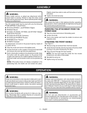
... eye protection with the guide recess on the coupler of the power head shaft and remove the end cap from the attachment. Push in the attachment's Operator's Manual. The use any attachment while power head is running. REMOVING THE ATTACHMENT FROM THE POWER HEAD Stop the motor and remove the battery pack. Loosen the knob. Push in objects being thrown into one side of the drive shaft housing in electric shock, fire and...
... eye protection with the guide recess on the coupler of the power head shaft and remove the end cap from the attachment. Push in the attachment's Operator's Manual. The use any attachment while power head is running. REMOVING THE ATTACHMENT FROM THE POWER HEAD Stop the motor and remove the battery pack. Loosen the knob. Push in objects being thrown into one side of the drive shaft housing in electric shock, fire and...
Operation Manual
Page 9
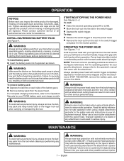
... rules and instructions in your tool when you are assembling parts, making adjustments, cleaning, or when not in use a brush cutter attachment with both hands while in operation. Hearing and/or head protection may also be taken when using a blade attachment and refer to comply with switch trigger completely depressed. English OPERATING THE POWER HEAD See Figures 7 - 8. Keep a firm grip with this product until all fasteners and caps and do...
... rules and instructions in your tool when you are assembling parts, making adjustments, cleaning, or when not in use a brush cutter attachment with both hands while in operation. Hearing and/or head protection may also be taken when using a blade attachment and refer to comply with switch trigger completely depressed. English OPERATING THE POWER HEAD See Figures 7 - 8. Keep a firm grip with this product until all fasteners and caps and do...

Operation Manual
Page 10
... handle. WARNING: When servicing, use ). GENERAL MAINTENANCE Avoid using a damp cloth with your product and do not operate this product until all foreign material from corrosive agents such as screws, nuts, bolts, caps, etc. They can result in a place that is depressed. English trigger is inaccessible to remove dirt, dust, oil, grease, etc. Charge the battery pack according to start when switch Battery is not secure. STORING THE POWER HEAD...
... handle. WARNING: When servicing, use ). GENERAL MAINTENANCE Avoid using a damp cloth with your product and do not operate this product until all foreign material from corrosive agents such as screws, nuts, bolts, caps, etc. They can result in a place that is depressed. English trigger is inaccessible to remove dirt, dust, oil, grease, etc. Charge the battery pack according to start when switch Battery is not secure. STORING THE POWER HEAD...

Parts Diagram
Page 1
REPAIR SHEET BRAND RYOBI MODEL NO. NO. Always mention this information in all communications regarding this product and when ordering parts. 11-22-21 (Rev:06) Box 1288, Anderson, SC 29622 1-800-525-2579 www.ryobitools.com The model number and manufacturing location will be found on a label attached to the product. P20104 315286001 P20104VNM 315286101 DESCRIPTION 18 Volt Brushless Power Head TTI OUTDOOR POWER EQUIPMENT, INC. MFG. P.O.
REPAIR SHEET BRAND RYOBI MODEL NO. NO. Always mention this information in all communications regarding this product and when ordering parts. 11-22-21 (Rev:06) Box 1288, Anderson, SC 29622 1-800-525-2579 www.ryobitools.com The model number and manufacturing location will be found on a label attached to the product. P20104 315286001 P20104VNM 315286101 DESCRIPTION 18 Volt Brushless Power Head TTI OUTDOOR POWER EQUIPMENT, INC. MFG. P.O.

Parts Diagram
Page 3
... QTY. 1 941588484 Data Label (P20104) 1 13 1 941588902 Data Label (P20104VNM) 1 15 14 660643008 Screw (1/4-20 x 40 mm, Hex Hd.) 1 2 15 518949001 Wing Nut (1/4-20) 1 1 315991001 Boom Assembly (Inc. Key No. 2 & 13) Logo Label Screw (M4 x 18 mm, T15 Torx Pan Hd.) Screw (M3 x 8 mm, Pan Hd.) Motor & Gear Box Assembly Motor Controller & Switch Assembly Motor Volute Assembly Variable Speed Switch Hi-Lo Switch Cover Switch Trigger Assembly Boom Clamp Assembly Front Handle Assembly (Inc.
... QTY. 1 941588484 Data Label (P20104) 1 13 1 941588902 Data Label (P20104VNM) 1 15 14 660643008 Screw (1/4-20 x 40 mm, Hex Hd.) 1 2 15 518949001 Wing Nut (1/4-20) 1 1 315991001 Boom Assembly (Inc. Key No. 2 & 13) Logo Label Screw (M4 x 18 mm, T15 Torx Pan Hd.) Screw (M3 x 8 mm, Pan Hd.) Motor & Gear Box Assembly Motor Controller & Switch Assembly Motor Volute Assembly Variable Speed Switch Hi-Lo Switch Cover Switch Trigger Assembly Boom Clamp Assembly Front Handle Assembly (Inc.

Parts Diagram
Page 4
P20104/P20104VNM BATTERY CONNECTOR BLACK VARIABLE SIGNAL SWITCH RED BRAKE YELLOW BLUE SWITCH MOTOR YELLOW BLACK BLACK BLACK MOTOR CONTROLLER BLUE RED RED BLUE WIRING DIAGRAM 4
P20104/P20104VNM BATTERY CONNECTOR BLACK VARIABLE SIGNAL SWITCH RED BRAKE YELLOW BLUE SWITCH MOTOR YELLOW BLACK BLACK BLACK MOTOR CONTROLLER BLUE RED RED BLUE WIRING DIAGRAM 4


