User Manual
Page 5
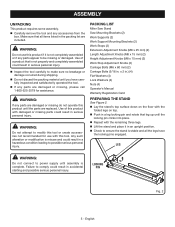
...Flat Washers (4) Lock Washers (4) Nuts (4) Operator's Manual Warranty Registration Card preparing the stand See Figure 2. n Carefully remove the tool and any parts appear to modify this product if it in a hazardous condition leading to power supply until you have the locking pins engaged. n Do not ...x 2 in . n Lift the stand and place it is stable and all items listed in serious personal injury. n If any parts are replaced. LEG WARNING: Do not connect to possible serious personal injury. ASSEMBLY UNPACKING This product requires some assembly. WARNING: Do not...
...Flat Washers (4) Lock Washers (4) Nuts (4) Operator's Manual Warranty Registration Card preparing the stand See Figure 2. n Carefully remove the tool and any parts appear to modify this product if it in a hazardous condition leading to power supply until you have the locking pins engaged. n Do not ...x 2 in . n Lift the stand and place it is stable and all items listed in serious personal injury. n If any parts are replaced. LEG WARNING: Do not connect to possible serious personal injury. ASSEMBLY UNPACKING This product requires some assembly. WARNING: Do not...
User Manual
Page 8
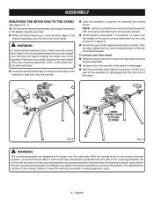
... designed to remove the saw and bracket assembly from the saw is fully seated and locked in the lowered (locked) position, you , lift the front part of the assembly to disengage. n While still tilted toward you should not be able to fit snugly over the rails, or if the mounting brackets...
... designed to remove the saw and bracket assembly from the saw is fully seated and locked in the lowered (locked) position, you , lift the front part of the assembly to disengage. n While still tilted toward you should not be able to fit snugly over the rails, or if the mounting brackets...
User Manual
Page 10
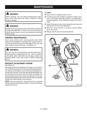
... needs to tighten or loosen the bracket adjustment screws. GENERAL MAINTENANCE Avoid using solvents when cleaning plastic parts. Saw mounting bracket wrench WARNING: Do not at any other parts may be loosened. If the saw and bracket assembly from the mounting brackets before attempting to be ...from the rails when the levers are designed to fit snugly over both rails, the bracket adjustment screws needs to comply with plastic parts. bracket ADJUSTMENT SCREW See Figure 12. With the locking levers in serious personal injury. English NOTE: The saw should not be ...
... needs to tighten or loosen the bracket adjustment screws. GENERAL MAINTENANCE Avoid using solvents when cleaning plastic parts. Saw mounting bracket wrench WARNING: Do not at any other parts may be loosened. If the saw and bracket assembly from the mounting brackets before attempting to be ...from the rails when the levers are designed to fit snugly over both rails, the bracket adjustment screws needs to comply with plastic parts. bracket ADJUSTMENT SCREW See Figure 12. With the locking levers in serious personal injury. English NOTE: The saw should not be ...
User Manual 2
Page 3
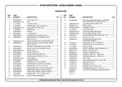
... 1 43 0000220213 REAR CLAMING JAW 1 44 0000220214 FRONT CLAMPING JAW 1 45 0000220803 SCREW A (PAN HD. - MODEL NUMBER A18MS01 PARTS LIST KEY PART NO. MAY BE PURCHASED LOCALLY 3 RYOBI MITER STAND - NUMBER DESCRIPTION QTY KEY PART NO. SPECIAL 1 47 0000220217 LEFT CAM 1 48 A000221501 MOUNTING BRACKET SCREW SET 1 49 411012706 * HEX NUT (5/16 in 4 50...
... 1 43 0000220213 REAR CLAMING JAW 1 44 0000220214 FRONT CLAMPING JAW 1 45 0000220803 SCREW A (PAN HD. - MODEL NUMBER A18MS01 PARTS LIST KEY PART NO. MAY BE PURCHASED LOCALLY 3 RYOBI MITER STAND - NUMBER DESCRIPTION QTY KEY PART NO. SPECIAL 1 47 0000220217 LEFT CAM 1 48 A000221501 MOUNTING BRACKET SCREW SET 1 49 411012706 * HEX NUT (5/16 in 4 50...
User Manual 3
Page 3
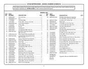
...mm, Truss Hd 2 Not Shown: 983000710 (Rev:04) 5-17-17 Work Frame Assembly 1 DESCRIPTION QTY Saw Mounting Bracket Assembly (Inc. RYOBI MITER STAND - KEY PART NO. Key Nos. 30-34 and 36-49 2 Locking Lever w/End Cap 1 Right Cam 1 Screw (M4 x 12 mm, Pan...16 in 4 Washer (5/16 x OD16 x 2t 4 Carriage Bolt (5/16-18 x 2 in all correspondence regarding your MITER STAND or when ordering replacement parts. NUMBER 1 0000220201 2 0000220301-57 3 411072006 4 410132044 5 0000220302-82 6 413052002 7 0000220901 8 0000220902 9 0000220801 10 089041017001 11 0000220303-82 12 ...
...mm, Truss Hd 2 Not Shown: 983000710 (Rev:04) 5-17-17 Work Frame Assembly 1 DESCRIPTION QTY Saw Mounting Bracket Assembly (Inc. RYOBI MITER STAND - KEY PART NO. Key Nos. 30-34 and 36-49 2 Locking Lever w/End Cap 1 Right Cam 1 Screw (M4 x 12 mm, Pan...16 in 4 Washer (5/16 x OD16 x 2t 4 Carriage Bolt (5/16-18 x 2 in all correspondence regarding your MITER STAND or when ordering replacement parts. NUMBER 1 0000220201 2 0000220301-57 3 411072006 4 410132044 5 0000220302-82 6 413052002 7 0000220901 8 0000220902 9 0000220801 10 089041017001 11 0000220303-82 12 ...


