Owners Manual
Page 1
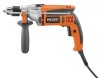
HAMMER DRILL DOUBLE INSULATED R5013 Your hammer drill has been engineered and manufactured to our high standard for buying a RIDGID product. SAVE THIS MANUAL FOR FUTURE REFERENCE 1 When properly cared for, it will give you for dependability, ease of injury, the user must read and understand the operator's manual before using this product. Thank you years of rugged, trouble-free performance. WARNING: To reduce the risk of operation, and operator safety. OPERATOR'S MANUAL 1/2 in.
HAMMER DRILL DOUBLE INSULATED R5013 Your hammer drill has been engineered and manufactured to our high standard for buying a RIDGID product. SAVE THIS MANUAL FOR FUTURE REFERENCE 1 When properly cared for, it will give you for dependability, ease of injury, the user must read and understand the operator's manual before using this product. Thank you years of rugged, trouble-free performance. WARNING: To reduce the risk of operation, and operator safety. OPERATOR'S MANUAL 1/2 in.
Owners Manual
Page 2
TABLE OF CONTENTS Introduction ...2 General Safety Rules ...3-4 Specific Safety Rules...4 Symbols...5-6 Electrical ...7 Features ...8-9 Assembly ...9 Operation ...10-15 Maintenance ...15-16 Warranty ...17 Customer Service Information...Back Page INTRODUCTION This product has many features for making it easy to maintain and operate. 2 Safety, performance, and dependability have been given top priority in the design of this product making its use more pleasant and enjoyable.
TABLE OF CONTENTS Introduction ...2 General Safety Rules ...3-4 Specific Safety Rules...4 Symbols...5-6 Electrical ...7 Features ...8-9 Assembly ...9 Operation ...10-15 Maintenance ...15-16 Warranty ...17 Customer Service Information...Back Page INTRODUCTION This product has many features for making it easy to maintain and operate. 2 Safety, performance, and dependability have been given top priority in the design of this product making its use more pleasant and enjoyable.
Owners Manual
Page 3
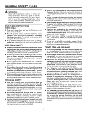
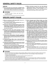
... safer at all instructions listed below refers to your mains-operated (corded) power tool or battery-operated (cordless) power tool. Damaged or entangled cords increase the risk of electric shock. When operating a power tool outdoors, use . Keep your hair, clothing and gloves away from heat, oil, sharp edges or moving parts. Loose clothes, jewelry, or long hair can cause you are easier to control. Use the power tool, accessories and tool bits etc., in...
... safer at all instructions listed below refers to your mains-operated (corded) power tool or battery-operated (cordless) power tool. Damaged or entangled cords increase the risk of electric shock. When operating a power tool outdoors, use . Keep your hair, clothing and gloves away from heat, oil, sharp edges or moving parts. Loose clothes, jewelry, or long hair can cause you are easier to control. Use the power tool, accessories and tool bits etc., in...
Owners Manual
Page 4
.... Check damaged parts. Following this type of electric shock, fire, or serious injury. Always wear safety glasses. The smaller the gauge number, the heavier the cord. To reduce your hearing. Before further use the next heavier gauge. If in a well ventilated area, and work . To reduce the risk of at your power tool. A wire gauge size (A.W.G.) of injury, user must be replaced only by the...
.... Check damaged parts. Following this type of electric shock, fire, or serious injury. Always wear safety glasses. The smaller the gauge number, the heavier the cord. To reduce your hearing. Before further use the next heavier gauge. If in a well ventilated area, and work . To reduce the risk of at your power tool. A wire gauge size (A.W.G.) of injury, user must be replaced only by the...
Owners Manual
Page 5
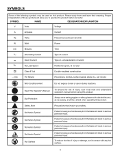
... use in serious personal injury. To reduce the risk of these symbols will allow you to keep your safety. SYMBOL NAME DESIGNATION/EXPLANATION V Volts Voltage A Amperes Current Hz Hertz Frequency (cycles per second) W Watt Power min Minutes Time Alternating Current Type of current Direct Current no No Load Speed Type or a characteristic of current Rotational speed, at no load Class II Tool...
... use in serious personal injury. To reduce the risk of these symbols will allow you to keep your safety. SYMBOL NAME DESIGNATION/EXPLANATION V Volts Voltage A Amperes Current Hz Hertz Frequency (cycles per second) W Watt Power min Minutes Time Alternating Current Type of current Direct Current no No Load Speed Type or a characteristic of current Rotational speed, at no load Class II Tool...
Owners Manual
Page 6
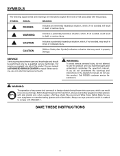
... a qualified service technician. Before beginning power tool operation, always wear safety goggles or safety glasses with ANSI Z87.1. CAUTION (Without Safety Alert Symbol) Indicates a situation that may result in the operator's manual, do not use this product until you do not attempt to use eye protection which , if not avoided, will result in severe eye damage. SAVE THESE INSTRUCTIONS 6 For service we suggest...
... a qualified service technician. Before beginning power tool operation, always wear safety goggles or safety glasses with ANSI Z87.1. CAUTION (Without Safety Alert Symbol) Indicates a situation that may result in the operator's manual, do not use this product until you do not attempt to use eye protection which , if not avoided, will result in severe eye damage. SAVE THESE INSTRUCTIONS 6 For service we suggest...
Owners Manual
Page 7
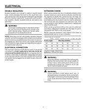
... exposed wires and cut or worn insulation. **Ampere rating (on tool data plate) 0-2.0 2.1-3.4 3.5-5.0 5.1-7.0 7.1-12.0 12.1-16.0 Cord Length Wire Size (A.W.G.) 25' 16 16 16 16 14 14 50' 16 16 16 14 14 12 100' 16 16 14 12 10 - **Used on direct current (DC). If damaged replace immediately. NOTE: Servicing of power. ELECTRICAL CONNECTION This tool has a precision-built electric motor. All exposed metal parts are working...
... exposed wires and cut or worn insulation. **Ampere rating (on tool data plate) 0-2.0 2.1-3.4 3.5-5.0 5.1-7.0 7.1-12.0 12.1-16.0 Cord Length Wire Size (A.W.G.) 25' 16 16 16 16 14 14 50' 16 16 16 14 14 12 100' 16 16 14 12 10 - **Used on direct current (DC). If damaged replace immediately. NOTE: Servicing of power. ELECTRICAL CONNECTION This tool has a precision-built electric motor. All exposed metal parts are working...
Owners Manual
Page 8
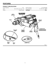
Input 120 V, 60 Hz, AC only, 7.5 A Switch Variable Speed Hammer Speed 0-51,000 BPM No Load Speed 0-2,700 r/min. (RPM) Net Weight 5 lbs. DEPTH STOP ROD DRILLING/HAMMER MODE SELECTOR CHUCK LOCK-ON BUTTON CHUCK KEY STRAP AUXILIARY HANDLE ASSEMBLY SWITCH TRIGGER DIRECTION OF ROTATION SELECTOR (FORWARD/REVERSE) P0WER CORD CHUCK KEY LIGHTED PLUG Fig. 1 8 FEATURES PRODUCT SPECIFICATIONS Chuck Capacity 1/2 in.
Input 120 V, 60 Hz, AC only, 7.5 A Switch Variable Speed Hammer Speed 0-51,000 BPM No Load Speed 0-2,700 r/min. (RPM) Net Weight 5 lbs. DEPTH STOP ROD DRILLING/HAMMER MODE SELECTOR CHUCK LOCK-ON BUTTON CHUCK KEY STRAP AUXILIARY HANDLE ASSEMBLY SWITCH TRIGGER DIRECTION OF ROTATION SELECTOR (FORWARD/REVERSE) P0WER CORD CHUCK KEY LIGHTED PLUG Fig. 1 8 FEATURES PRODUCT SPECIFICATIONS Chuck Capacity 1/2 in.
Owners Manual
Page 9
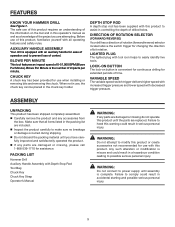
... on button is equipped with Depth Stop Rod Tool Bag Chuck Key Chuck Key Strap Operator's Manual WARNING: If any accessories from the box. Make sure that all operating features and safety rules. The safe use of this product requires an understanding of drilled holes. DIRECTION OF ROTATION SELECTOR (FORWARD/REVERSE) Your drill has a direction of rotation (forward/reverse) selector located above the switch trigger for extended periods of operation and...
... on button is equipped with Depth Stop Rod Tool Bag Chuck Key Chuck Key Strap Operator's Manual WARNING: If any accessories from the box. Make sure that all operating features and safety rules. The safe use of this product requires an understanding of drilled holes. DIRECTION OF ROTATION SELECTOR (FORWARD/REVERSE) Your drill has a direction of rotation (forward/reverse) selector located above the switch trigger for extended periods of operation and...
Owners Manual
Page 10
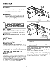
... switch trigger. To stop the drill, release the switch trigger and allow the chuck to come to make you careless. LOCK-ON BUTTON WARNING: Always wear safety goggles or safety glasses with decreased trigger pressure. Failure to a complete stop before changing the direction of this occurs, cool the drill by a selector located above the switch trigger. NOTE: You might hear a whistling or ringing noise from the switch during use any attachments or accessories...
... switch trigger. To stop the drill, release the switch trigger and allow the chuck to come to make you careless. LOCK-ON BUTTON WARNING: Always wear safety goggles or safety glasses with decreased trigger pressure. Failure to a complete stop before changing the direction of this occurs, cool the drill by a selector located above the switch trigger. NOTE: You might hear a whistling or ringing noise from the switch during use any attachments or accessories...

Owners Manual
Page 11
... chuck jaws using the chuck key provided. Remove the chuck key. OPERATION TO INSTALL BITS See Figures 4 - 5 Unplug the drill. Insert the chuck key and twist counterclockwise. Open or close the chuck jaws to a point where the opening is slightly larger than the bit size you intend to the chuck. Insert the drill bit. Tighten the chuck jaws securely on the drill bit, using the chuck key provided. Remove the drill bit. Remove the chuck key...
... chuck jaws using the chuck key provided. Remove the chuck key. OPERATION TO INSTALL BITS See Figures 4 - 5 Unplug the drill. Insert the chuck key and twist counterclockwise. Open or close the chuck jaws to a point where the opening is slightly larger than the bit size you intend to the chuck. Insert the drill bit. Tighten the chuck jaws securely on the drill bit, using the chuck key provided. Remove the drill bit. Remove the chuck key...

Owners Manual
Page 12
... drilled holes. To adjust the auxiliary handle assembly, Loosen the handle assembly by turning the handle counterclockwise. Rotate the auxiliary handle assembly to help prevent loss of starting threads, the hex nut has been trapped inside the molded slot in contact with the drill for left hand use. NOTE: For convenience and ease of control. An auxiliary handle is securely tightened against the depth stop clamp. NOTE: When properly installed...
... drilled holes. To adjust the auxiliary handle assembly, Loosen the handle assembly by turning the handle counterclockwise. Rotate the auxiliary handle assembly to help prevent loss of starting threads, the hex nut has been trapped inside the molded slot in contact with the drill for left hand use. NOTE: For convenience and ease of control. An auxiliary handle is securely tightened against the depth stop clamp. NOTE: When properly installed...
Owners Manual
Page 13
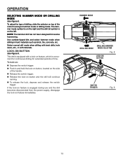
... for type of the motor housing to hammer mode or drilling mode. Use carbide-tipped bits and select hammer mode when drilling in and hold the lock-on button, located on the side of the handle. Release the switch trigger. Release the lock-on top of drilling, slide the selector on button and the drill will continue running. To release the lock, depress and release the switch trigger. OPERATION SELECTING HAMMER MODE OR DRILLING MODE...
... for type of the motor housing to hammer mode or drilling mode. Use carbide-tipped bits and select hammer mode when drilling in and hold the lock-on button, located on the side of the handle. Release the switch trigger. Release the lock-on top of drilling, slide the selector on button and the drill will continue running. To release the lock, depress and release the switch trigger. OPERATION SELECTING HAMMER MODE OR DRILLING MODE...
Owners Manual
Page 14
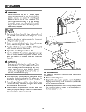
... the drill stalls, stop the tool immediately. The oil will prevent the drill bit from slipping off the starting of rotation selector for binding at a very low speed to keep the bit cutting. DRILLING See Figure 10 Depress and release the switch trigger to be sure the drill is in the OFF position before connecting it to a power supply. Check the direction of the drill resulting...
... the drill stalls, stop the tool immediately. The oil will prevent the drill bit from slipping off the starting of rotation selector for binding at a very low speed to keep the bit cutting. DRILLING See Figure 10 Depress and release the switch trigger to be sure the drill is in the OFF position before connecting it to a power supply. Check the direction of the drill resulting...
Owners Manual
Page 15
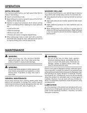
... servicing use only identical RIDGID replacement parts. Use of commercial solvents and may create a hazard or cause product damage. GENERAL MAINTENANCE Avoid using this product are highly abrasive to bearings, brushes, commutators, etc. Use clean cloths to determine the best speed and pressure. MASONRY DRILLING For maximum performance, use carbide-tipped masonry impact bits when drilling holes in brick, tile, concrete, etc. Slide adjustment button on a scrap piece to remove dirt, dust, oil...
... servicing use only identical RIDGID replacement parts. Use of commercial solvents and may create a hazard or cause product damage. GENERAL MAINTENANCE Avoid using this product are highly abrasive to bearings, brushes, commutators, etc. Use clean cloths to determine the best speed and pressure. MASONRY DRILLING For maximum performance, use carbide-tipped masonry impact bits when drilling holes in brick, tile, concrete, etc. Slide adjustment button on a scrap piece to remove dirt, dust, oil...

Owners Manual
Page 16
... CHUCK The chuck may be unscrewed by turning it in a clockwise direction. This will loosen the chuck on the spindle. Open the chuck jaws and remove the hex key. Tighten the chuck screw with a screwdriver. This will loosen the screw in a clockwise direction. This will tighten the chuck on the spindle. NOTE: The screw has left hand threads. Insert the hex key into the chuck and tighten the chuck jaws securely. MAINTENANCE CHUCK REMOVAL See...
... CHUCK The chuck may be unscrewed by turning it in a clockwise direction. This will loosen the chuck on the spindle. Open the chuck jaws and remove the hex key. Tighten the chuck screw with a screwdriver. This will loosen the screw in a clockwise direction. This will tighten the chuck on the spindle. NOTE: The screw has left hand threads. Insert the hex key into the chuck and tighten the chuck jaws securely. MAINTENANCE CHUCK REMOVAL See...
Owners Manual
Page 17
... for other rights which vary from the date of purchase, if you are dissatisfied with the tool such as brushes, chucks, motors, switches, cords, gears and even cordless batteries in to One World Technologies, Inc., attn: RIDGID Hand Held and Stationary Power Tool Technical Service at www.ridgid.com. Warranties for a full refund or exchange. RIDGID, INC. freight prepaid, or take it ; WHAT IS NOT COVERED This...
... for other rights which vary from the date of purchase, if you are dissatisfied with the tool such as brushes, chucks, motors, switches, cords, gears and even cordless batteries in to One World Technologies, Inc., attn: RIDGID Hand Held and Stationary Power Tool Technical Service at www.ridgid.com. Warranties for a full refund or exchange. RIDGID, INC. freight prepaid, or take it ; WHAT IS NOT COVERED This...

Owners Manual
Page 18
HAMMER DRILL DOUBLE INSULATED R5013 Customer Service Information: For parts or service, contact your nearest RIDGID authorized service center. Be sure to the motor housing. R5013 Serial No. 987000-060 01-23-07 (REV:00) 18 When ordering repair parts, always give the following information: Model No. For the location of this tool is found on a plate attached to provide all relevant information when you , please call...
HAMMER DRILL DOUBLE INSULATED R5013 Customer Service Information: For parts or service, contact your nearest RIDGID authorized service center. Be sure to the motor housing. R5013 Serial No. 987000-060 01-23-07 (REV:00) 18 When ordering repair parts, always give the following information: Model No. For the location of this tool is found on a plate attached to provide all relevant information when you , please call...


