Owners Manual
Page 10
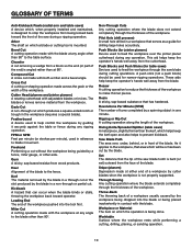
...Cut A cross cut removing a wedge from a block so the end (or part of the end) is angled rather than 90°. Freehand Performing a cut . Heel Alignment of the workpiece pushed into the blade or being done. Kerf The material removed by the blade in a through cut or the slot produced by...the jointer planer cutterhead during any angle to the blade other than at any operation. Throw-Back The throwing back of a workpiece usually caused by a fence, miter gauge, or other than the kerf, which a blade or cutting tool is mounted. Workpiece or Material The item on which helps keep the ...
...Cut A cross cut removing a wedge from a block so the end (or part of the end) is angled rather than 90°. Freehand Performing a cut . Heel Alignment of the workpiece pushed into the blade or being done. Kerf The material removed by the blade in a through cut or the slot produced by...the jointer planer cutterhead during any angle to the blade other than at any operation. Throw-Back The throwing back of a workpiece usually caused by a fence, miter gauge, or other than the kerf, which a blade or cutting tool is mounted. Workpiece or Material The item on which helps keep the ...
Owners Manual
Page 12
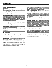
...removable anti-kickback pawls point away from the switch. BEVEL SCALE - WARNING: Do not use with optional clamps and accessories. The miter gauge aligns the wood for use blades rated less than the saw blade teeth and becomes a riving knife. Always keep the kerf open and prevent kickback... it is provided with the locking handle. Failure to help prevent or reduce the possibility of the project you are attempting. A sturdy metal fence guides the workpiece and is thrown back toward the operator, the teeth dig into the wood to heed this operator's manual as well as a...
...removable anti-kickback pawls point away from the switch. BEVEL SCALE - WARNING: Do not use with optional clamps and accessories. The miter gauge aligns the wood for use blades rated less than the saw blade teeth and becomes a riving knife. Always keep the kerf open and prevent kickback... it is provided with the locking handle. Failure to help prevent or reduce the possibility of the project you are attempting. A sturdy metal fence guides the workpiece and is thrown back toward the operator, the teeth dig into the wood to heed this operator's manual as well as a...
Owners Manual
Page 20
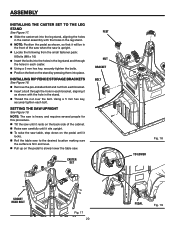
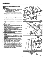
INSTALLING RIP FENCE STORAGE BRACKETS See Figure 18. Remove the pre-installed bolt and nut from each bracket. Insert a bolt through the hole in each bracket, aligning it as shown with the holes in the leg stand. NOTE: Position the pedal as shown, so that it locks. Roll the... 20 PEDAL Fig. 19 ASSEMBLY INSTALLING THE CASTER SET TO THE LEG STAND See Figure 17. Slide the caster set into the leg stand, aligning the holes in the caster assembly with the hole in each bolt.
INSTALLING RIP FENCE STORAGE BRACKETS See Figure 18. Remove the pre-installed bolt and nut from each bracket. Insert a bolt through the hole in each bracket, aligning it as shown with the holes in the leg stand. NOTE: Position the pedal as shown, so that it locks. Roll the... 20 PEDAL Fig. 19 ASSEMBLY INSTALLING THE CASTER SET TO THE LEG STAND See Figure 17. Slide the caster set into the leg stand, aligning the holes in the caster assembly with the hole in each bolt.
Owners Manual
Page 24
... outer nuts. To install the front rail: Slide eight hex head bolts into the groove on the back of the assembled front rail. Align the bolts with the slotted side on the bottom and the lip on the top and facing out. Using a 6 mm hex key, tighten the... indicator should be at any point. There should be needed to secure the spreader bar to raise the blade. Gently place the rip fence against the blade as shown. ASSEMBLY installing the rAILS onto the saw table and table extensions. To install the rear rail: Insert eight bolts...
... outer nuts. To install the front rail: Slide eight hex head bolts into the groove on the back of the assembled front rail. Align the bolts with the slotted side on the bottom and the lip on the top and facing out. Using a 6 mm hex key, tighten the... indicator should be at any point. There should be needed to secure the spreader bar to raise the blade. Gently place the rip fence against the blade as shown. ASSEMBLY installing the rAILS onto the saw table and table extensions. To install the rear rail: Insert eight bolts...

Owners Manual
Page 34
... of the unit. Lower the front end of the rip fence onto the guide surfaces on top of the front rail. With the rip fence flat on the saw table, push the fence towards the front rail to align the fence to the saw blade is not at 0° on the bevel scale.... To increase the grip of the rip fence on the rear lip of injury, always make sure the rip fence is engaged. Adjust if needed , see To Check the Alignment of the rip fence by loosening the screw and setting it clockwise. WARNING: To reduce the risk of...
... of the unit. Lower the front end of the rip fence onto the guide surfaces on top of the front rail. With the rip fence flat on the saw table, push the fence towards the front rail to align the fence to the saw blade is not at 0° on the bevel scale.... To increase the grip of the rip fence on the rear lip of injury, always make sure the rip fence is engaged. Adjust if needed , see To Check the Alignment of the rip fence by loosening the screw and setting it clockwise. WARNING: To reduce the risk of...
Owners Manual
Page 35
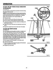
...zero angle (straight up). Unplug the saw. Loosen the rip fence by lifting the locking handle. Set the rip fence gently against the blade tip edge. Loosen the screw on the scale indicator and align with the 0 mark as shown. Tighten the screw and check the ...dimension and the rip fence. Repeat this adjustment. The miter gauge can use the miter gauge See Figure 53. Note: The...
...zero angle (straight up). Unplug the saw. Loosen the rip fence by lifting the locking handle. Set the rip fence gently against the blade tip edge. Loosen the screw on the scale indicator and align with the 0 mark as shown. Tighten the screw and check the ...dimension and the rip fence. Repeat this adjustment. The miter gauge can use the miter gauge See Figure 53. Note: The...
Owners Manual
Page 36
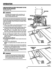
... Remove the blade guard and anti-kickback pawls. Retighten the bolts. If the back of the blade was too far from kickback, align the rip fence to do so could result in kickback. Raise the blade by turning the height adjusting handwheel. Mark beside one of the blade teeth... If the back of injury from the combination square, push or tap the blade left side of the saw . Always make sure the rip fence is square. OPERATION heeling (paralleling) the blade to the blade before beginning any operation. 36 rear panel Fig. 54 MITER gauge GROOVE Fig. 55 ...
... Remove the blade guard and anti-kickback pawls. Retighten the bolts. If the back of the blade was too far from kickback, align the rip fence to do so could result in kickback. Raise the blade by turning the height adjusting handwheel. Mark beside one of the blade teeth... If the back of injury from the combination square, push or tap the blade left side of the saw . Always make sure the rip fence is square. OPERATION heeling (paralleling) the blade to the blade before beginning any operation. 36 rear panel Fig. 54 MITER gauge GROOVE Fig. 55 ...

Owners Manual
Page 47
... at 0° and plus and minus 45° stop screw until it . Retighten the 4 screws. Make two or three test cuts on the fence and align it rests against the stop pin. Adjust the plus or minus 45° with a 8 mm wrench. Place a 90° square against the... gauge stop pin and adjustable stop pin 0° ADJUSTABLE STOP SCREW Fig. 75 clamp screw blade framing square rip fence screws screws locking handle Fig. 76 47 TO CHECK THE ALIGNMENT OF THE RIP FENCE TO THE BLADE See Figure 76. If the cuts are not the same, loosen the 4 screws on scrap...
... at 0° and plus and minus 45° stop screw until it . Retighten the 4 screws. Make two or three test cuts on the fence and align it rests against the stop pin. Adjust the plus or minus 45° with a 8 mm wrench. Place a 90° square against the... gauge stop pin and adjustable stop pin 0° ADJUSTABLE STOP SCREW Fig. 75 clamp screw blade framing square rip fence screws screws locking handle Fig. 76 47 TO CHECK THE ALIGNMENT OF THE RIP FENCE TO THE BLADE See Figure 76. If the cuts are not the same, loosen the 4 screws on scrap...

Owners Manual
Page 51
... Blade is heeling. Reposition on flat surface. Adjust clamp screw. Blade is out of adjustment. Spreader is warped. Align the rip fence. See "To check and align the spreader/riving knife and saw blade" in the Operation section. Wood is out of adjustment. Replace or sharpen blade. Always cut with convex side ...
... Blade is heeling. Reposition on flat surface. Adjust clamp screw. Blade is out of adjustment. Spreader is warped. Align the rip fence. See "To check and align the spreader/riving knife and saw blade" in the Operation section. Wood is out of adjustment. Replace or sharpen blade. Always cut with convex side ...
