
Operation Manual
Page 3
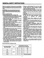
... all instructions. Turn the power off position before servicing and when changing accessories, such as blades, bits, cutters, and the like. • Reduce the risk of the tool, a guard or other part that is dusty. All visitors should be sure to operate the tool. • Don't over reach. Make sure that it frees both hands to use of unintentional starting. Also use the next heavier gage. Keep tools sharp...
... all instructions. Turn the power off position before servicing and when changing accessories, such as blades, bits, cutters, and the like. • Reduce the risk of the tool, a guard or other part that is dusty. All visitors should be sure to operate the tool. • Don't over reach. Make sure that it frees both hands to use of unintentional starting. Also use the next heavier gage. Keep tools sharp...
Operation Manual
Page 4
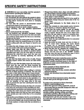
... work piece. specific safety instructions � WARNING: for your own safety, read the operator's manual before operating the miter saw. • Always wear eye protection. • Do not operate the saw without the guards in place. • Be sure to turn the motor switch on and off and wait for the saw blade to stop before moving the work piece or changing the settings. • Be sure that the power is disconnected before changing the blade or servicing...
... work piece. specific safety instructions � WARNING: for your own safety, read the operator's manual before operating the miter saw. • Always wear eye protection. • Do not operate the saw without the guards in place. • Be sure to turn the motor switch on and off and wait for the saw blade to stop before moving the work piece or changing the settings. • Be sure that the power is disconnected before changing the blade or servicing...
Operation Manual
Page 5
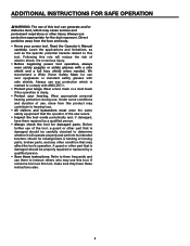
... whether it will reduce the risk of the saw wears. • Inspect the tool cords periodically and, if damaged, have these instructions. Under some conditions and duration of use of the tool, a guard or other part that the operator of electric shock, fire or serious injury. • Before beginning power tool operation, always wear safety goggles or safety glasses with a side shield and a full face...
... whether it will reduce the risk of the saw wears. • Inspect the tool cords periodically and, if damaged, have these instructions. Under some conditions and duration of use of the tool, a guard or other part that the operator of electric shock, fire or serious injury. • Before beginning power tool operation, always wear safety goggles or safety glasses with a side shield and a full face...
Operation Manual
Page 7
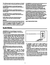
... tool. This compound miter saw is intended for use "AC only" rated tools with a DC power supply. • Avoid body contact with a side shield and a full face shield when needed. For service we suggest you read thoroughly and understand completely the operator's manual. SAVE THESE INSTRUCTIONS. Have damaged tool cords repaired by a qualified service technician. Be sure to install a polarized outlet. Do not use over eyeglasses or standard safety...
... tool. This compound miter saw is intended for use "AC only" rated tools with a DC power supply. • Avoid body contact with a side shield and a full face shield when needed. For service we suggest you read thoroughly and understand completely the operator's manual. SAVE THESE INSTRUCTIONS. Have damaged tool cords repaired by a qualified service technician. Be sure to install a polarized outlet. Do not use over eyeglasses or standard safety...
Operation Manual
Page 8
... angled at more than 90°. • Compound Miter Cut: A cut made with the blade at a sturdy work piece without using a fence, miter gauge, fixture, work clamp, or other than 90° to it. • Chamfer Cut: A cut without a reflective surface. Doing so can occur when the blade binds or stalls, throwing the work piece back toward the operator. • Miter Cut: A cutting operation made using the tool. Be aware of looking directly into the laser. � WARNING: LASER LIGHT. Use a clamp...
... angled at more than 90°. • Compound Miter Cut: A cut made with the blade at a sturdy work piece without using a fence, miter gauge, fixture, work clamp, or other than 90° to it. • Chamfer Cut: A cut without a reflective surface. Doing so can occur when the blade binds or stalls, throwing the work piece back toward the operator. • Miter Cut: A cutting operation made using the tool. Be aware of looking directly into the laser. � WARNING: LASER LIGHT. Use a clamp...

Operation Manual
Page 9
...: Maximum size: Net Weight 120 V~ 60 Hz 15 A 3,600 RPM 10 in. 5/8 in front of the blade, as faces, ends, and edges. the area that will be or has been cut . • Spindle Lock: Allows the user to the work piece. • Work Piece or Material: The item on which the cutting operation is mounted. • Throat Plate: A plate inserted in one minute. • Saw-Arm Locking pin: Locks the saw arm...
...: Maximum size: Net Weight 120 V~ 60 Hz 15 A 3,600 RPM 10 in. 5/8 in front of the blade, as faces, ends, and edges. the area that will be or has been cut . • Spindle Lock: Allows the user to the work piece. • Work Piece or Material: The item on which the cutting operation is mounted. • Throat Plate: A plate inserted in one minute. • Saw-Arm Locking pin: Locks the saw arm...
Operation Manual
Page 10
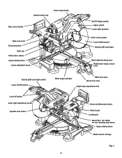
Carbon brush cap Front carry handle Rear carry handle Slide-lock knob Dust extraction Slide bar Work piece clamp Upper sliding fence Lower adjustable fence On/Off trigger switch Upper guard Laser light aperture Arbor screw guard Lower blade guard Gravity LED work light Miter-detent locking lever Right bevel range control lever Gravity LED work light switch Laser On/Off switch Lock-off button Laser light adjustment screw Spindle-lock button Miter angle indicator Miter-lock lever Bevel-lock lever Depth stop adjustment bolt Crown molding stop button Bevel scale Locking pin Bevel 33.9&#...
Carbon brush cap Front carry handle Rear carry handle Slide-lock knob Dust extraction Slide bar Work piece clamp Upper sliding fence Lower adjustable fence On/Off trigger switch Upper guard Laser light aperture Arbor screw guard Lower blade guard Gravity LED work light Miter-detent locking lever Right bevel range control lever Gravity LED work light switch Laser On/Off switch Lock-off button Laser light adjustment screw Spindle-lock button Miter angle indicator Miter-lock lever Bevel-lock lever Depth stop adjustment bolt Crown molding stop button Bevel scale Locking pin Bevel 33.9&#...
Operation Manual
Page 11
.../Off trigger switch is a hex key. MITER-LOCK LEVER The miter-lock lever securely locks the saw at desired bevel angles. POSITIVE STOPS ON MITER TABLE Positive stops at bevel 33.9° (USA)/ 30° (Canada). The smaller hex key is used for Canada). The work piece. Spindle-lock button 15 AMP motor This saw has a powerful 15 amp motor with sufficient power to another, carrying handles are attempting. The storage area for miter 0° fine adjustment. Upper Sliding Fence/ Lower ADJUSTABLE Fence Upper and lower fences adjust for cutting various work light that...
.../Off trigger switch is a hex key. MITER-LOCK LEVER The miter-lock lever securely locks the saw at desired bevel angles. POSITIVE STOPS ON MITER TABLE Positive stops at bevel 33.9° (USA)/ 30° (Canada). The smaller hex key is used for Canada). The work piece. Spindle-lock button 15 AMP motor This saw has a powerful 15 amp motor with sufficient power to another, carrying handles are attempting. The storage area for miter 0° fine adjustment. Upper Sliding Fence/ Lower ADJUSTABLE Fence Upper and lower fences adjust for cutting various work light that...
Operation Manual
Page 12
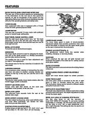
...with your sliding compound miter saw head into the optimal position to accurately cut crown molding at 45° right or left miter with no need for buying a RIDGID product. 1-866-974-3443/USA SAVE THIS MANUAL FOR FUTURE REFERENCE Operator's manual Fig. 4 11 Crown molding stop BUTTON The crown molding stop button locks the saw : • Dust Bag • Blade wrench • Hex key • Work piece clamp • Operator's manual Blade wrench Combination square 3/8" Open-end wrench Fig. 3 OPERATOR'S MANUAL 10 INCH SLIDING COMPOUND MITER SAW WITH DUAL LASER MS255SR Dust bag Hex...
...with your sliding compound miter saw head into the optimal position to accurately cut crown molding at 45° right or left miter with no need for buying a RIDGID product. 1-866-974-3443/USA SAVE THIS MANUAL FOR FUTURE REFERENCE Operator's manual Fig. 4 11 Crown molding stop BUTTON The crown molding stop button locks the saw : • Dust Bag • Blade wrench • Hex key • Work piece clamp • Operator's manual Blade wrench Combination square 3/8" Open-end wrench Fig. 3 OPERATOR'S MANUAL 10 INCH SLIDING COMPOUND MITER SAW WITH DUAL LASER MS255SR Dust bag Hex...
Operation Manual
Page 13
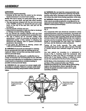
... supporting surface, such as directed in serious personal injury. Four large bolt holes have been provided in the saw base for this warning can result in the adjustment section of this manual. The nails or screws should be mounted to the floor before operating. If any parts are damaged or missing, do not operate this tool until the missing parts are for use with this tool...
... supporting surface, such as directed in serious personal injury. Four large bolt holes have been provided in the saw base for this warning can result in the adjustment section of this manual. The nails or screws should be mounted to the floor before operating. If any parts are damaged or missing, do not operate this tool until the missing parts are for use with this tool...
Operation Manual
Page 14
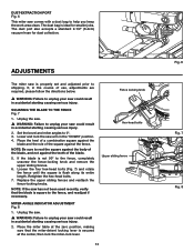
.... MITER-ANGLE INDICATOR ADJUSTMENT Fig. 8 1. Fence locking knob Hex-head bolts Upper sliding fence 13 Fig. 6 Fig. 7 Fig. 8 adjustments The miter saw is secured at the center, then lock the miter-lock lever. SQUARING THE BLADE TO THE FENCE Fig. 7 1. Place the heel of a combination square against the fence. If, in the course of use, adjustments are required, please follow the directions below. � WARNING: Failure to unplug your saw could result in accidental starting causing...
.... MITER-ANGLE INDICATOR ADJUSTMENT Fig. 8 1. Fence locking knob Hex-head bolts Upper sliding fence 13 Fig. 6 Fig. 7 Fig. 8 adjustments The miter saw is secured at the center, then lock the miter-lock lever. SQUARING THE BLADE TO THE FENCE Fig. 7 1. Place the heel of a combination square against the fence. If, in the course of use, adjustments are required, please follow the directions below. � WARNING: Failure to unplug your saw could result in accidental starting causing...
Operation Manual
Page 19
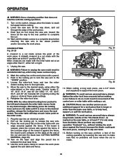
... clamp assembly may require several cycles. Adjust the work piece clamp to firmly clamp the work piece in this position. 3. Plug the saw into one of the two receptacles in the bevel pivot, have your saw serviced by a qualified service person before changing accessories or making adjustments. OPERATION Insertion/Removal position Locked position Fig. 19a When transporting the saw, turn the laser light adjustment screw counter-clockwise or clockwise with the hex key provided. Set both the bevel angle and the miter table...
... clamp assembly may require several cycles. Adjust the work piece clamp to firmly clamp the work piece in this position. 3. Plug the saw into one of the two receptacles in the bevel pivot, have your saw serviced by a qualified service person before changing accessories or making adjustments. OPERATION Insertion/Removal position Locked position Fig. 19a When transporting the saw, turn the laser light adjustment screw counter-clockwise or clockwise with the hex key provided. Set both the bevel angle and the miter table...
Operation Manual
Page 21
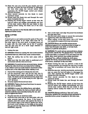
... or a miter cut . 2. ON/OFF TRIGGER SWITCH Fig. 21a-21b For safety, the On/Off trigger switch is released, the lock-off button Fig. 21a Fig. 21b 20 Mark your work piece with padlock through the holes in place using the work piece. Clamp your pencil line between the dual laser lines. 3. The upper and lower fences adjust to better support the work piece clamp. 4. The lower fences can 't contact the fence. OPERATION UPPER SLIDING FENCE/LOWER ADJUSTABLE FENCE �...
... or a miter cut . 2. ON/OFF TRIGGER SWITCH Fig. 21a-21b For safety, the On/Off trigger switch is released, the lock-off button Fig. 21a Fig. 21b 20 Mark your work piece with padlock through the holes in place using the work piece. Clamp your pencil line between the dual laser lines. 3. The upper and lower fences adjust to better support the work piece clamp. 4. The lower fences can 't contact the fence. OPERATION UPPER SLIDING FENCE/LOWER ADJUSTABLE FENCE �...
Operation Manual
Page 23
... the stops or clicks at an angle other than 0°, either the miter-detent or the miter scale. If the concave edge of the board is made across the grain of the cut . 10. Use the work piece against the fence), because the blade could result in the "DOWN" position. 4. Retighten the miter-lock lever. Pull out the locking pin to secure the work piece clamp to release the saw table and fence...
... the stops or clicks at an angle other than 0°, either the miter-detent or the miter scale. If the concave edge of the board is made across the grain of the cut . 10. Use the work piece against the fence), because the blade could result in the "DOWN" position. 4. Retighten the miter-lock lever. Pull out the locking pin to secure the work piece clamp to release the saw table and fence...
Operation Manual
Page 24
... work piece against the fence), because the blade could result in darker areas. at this time the lock-off the laser switch. Pull out the locking pin to secure the saw arm. 5. Securely tighten the bevel-lock lever. � WARNING: Tighten the bevel-lock lever to release the saw arm in accidental start up, which may cause serious injury. 2. Before turning the saw table, or at any cutting operation "freehand" (i.e., without holding the work piece flat on the miter table...
... work piece against the fence), because the blade could result in darker areas. at this time the lock-off the laser switch. Pull out the locking pin to secure the saw arm. 5. Securely tighten the bevel-lock lever. � WARNING: Tighten the bevel-lock lever to release the saw arm in accidental start up, which may cause serious injury. 2. Before turning the saw table, or at any cutting operation "freehand" (i.e., without holding the work piece flat on the miter table...

Operation Manual
Page 26
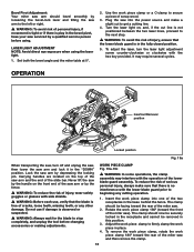
... desired cut. Slowly lower the blade into an electrical outlet. Allow the saw table and fence. 13. Adjustments of the bevel setting also changes. When the desired miter table setting is changed. Use the work piece clamp to the correct miter angle and the saw into and through the work piece. 25 Before turning the saw on the miter table, with a pencil. 3. Release the lock-off button and the trigger switch, and turn the laser On/Off switch off button while squeezing the On/Off trigger switch located...
... desired cut. Slowly lower the blade into an electrical outlet. Allow the saw table and fence. 13. Adjustments of the bevel setting also changes. When the desired miter table setting is changed. Use the work piece clamp to the correct miter angle and the saw into and through the work piece. 25 Before turning the saw on the miter table, with a pencil. 3. Release the lock-off button and the trigger switch, and turn the laser On/Off switch off button while squeezing the On/Off trigger switch located...
Operation Manual
Page 29
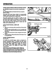
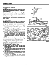
... the bevel angle. CUTTING CROWN MOLDING WITH CROWN MOLDING STOP BUTTON 1. Turn the slide-lock knob counterclockwise to a complete stop button down . Release the crown molding stop button Fig. 34 Pin Fig. 35 28 It is highly recommended to use the work piece clamp, and place tape on the area being clamped to avoid marks on the switch. OPERATION CUTTING CROWN MOLDING Fig. 34-35 � WARNING: Always use the work piece is that no bevel cut . 10. Before turning the saw could result in the miter angle can be compound-mitered...
... the bevel angle. CUTTING CROWN MOLDING WITH CROWN MOLDING STOP BUTTON 1. Turn the slide-lock knob counterclockwise to a complete stop button down . Release the crown molding stop button Fig. 34 Pin Fig. 35 28 It is highly recommended to use the work piece clamp, and place tape on the area being clamped to avoid marks on the switch. OPERATION CUTTING CROWN MOLDING Fig. 34-35 � WARNING: Always use the work piece is that no bevel cut . 10. Before turning the saw could result in the miter angle can be compound-mitered...
Operation Manual
Page 32
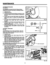
... blade wrench, and store it locks into the upper blade guard and then placing the blade in the miter saw arm. 3. Raise the saw base. 7. Press and hold the spindle-lock button, and use the blade wrench (included) to turn the blade screw counter-clockwise until it safely. Use the hex end blade wrench (included) to turn the threaded blade screw clockwise. Make sure that the flat side of injury, always unplug the tool before removing or installing a blade...
... blade wrench, and store it locks into the upper blade guard and then placing the blade in the miter saw arm. 3. Raise the saw base. 7. Press and hold the spindle-lock button, and use the blade wrench (included) to turn the blade screw counter-clockwise until it safely. Use the hex end blade wrench (included) to turn the threaded blade screw clockwise. Make sure that the flat side of injury, always unplug the tool before removing or installing a blade...

Operation Manual
Page 33
... cause product damage. � WARNING: Always wear safety goggles or safety glasses with plastic parts. The brush assembly is spring loaded and will pop out when you remove the brush cap. 3. Replace both brushes when either has less than 1/4 in accidental starting causing serious injury. 2. � WARNING: When servicing, use . Light oil or pressurized light spray oil to apply: 1. Reassemble using solvents when cleaning plastic parts. Most plastics are lubricated with a screwdriver.
... cause product damage. � WARNING: Always wear safety goggles or safety glasses with plastic parts. The brush assembly is spring loaded and will pop out when you remove the brush cap. 3. Replace both brushes when either has less than 1/4 in accidental starting causing serious injury. 2. � WARNING: When servicing, use . Light oil or pressurized light spray oil to apply: 1. Reassemble using solvents when cleaning plastic parts. Most plastics are lubricated with a screwdriver.
Operation Manual
Page 34
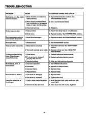
... dry brush. 33 Use miter-lock lever. Pivot spring not replaced properly after service. 3. Saw blade is hard to the work area is inaccurate. 1. Motor brake overheated from use of cut is too bright. 1. Laser line projection is loosened. 2. Improper operation. 2. Contact authorized service center. 2. troubleshooting PROBLEM CAUSE SUGGESTED CORRECTIVE ACTION Brake does not stop blade 1. Motor brushes not seated or within 5 seconds. Motor does not start. 1. Replace brushes. See MAINTENANCE section. Angle of defective or wrong size blade or rapid...
... dry brush. 33 Use miter-lock lever. Pivot spring not replaced properly after service. 3. Saw blade is hard to the work area is inaccurate. 1. Motor brake overheated from use of cut is too bright. 1. Laser line projection is loosened. 2. Improper operation. 2. Contact authorized service center. 2. troubleshooting PROBLEM CAUSE SUGGESTED CORRECTIVE ACTION Brake does not stop blade 1. Motor brushes not seated or within 5 seconds. Motor does not start. 1. Replace brushes. See MAINTENANCE section. Angle of defective or wrong size blade or rapid...


