
Owners Manual
Page 2
... Safety 2 Equipment Use and Care 2 Service ...3 Specific Safety Information micro CA-100 Inspection Camera Safety 3 Description, Specifications and Standard Equipment Description ...4 Specifications...4 Standard Equipment 4 Controls ...4 FCC Statement ...5 Electromagnetic Compatibility (EMC 5 Tool Assembly Changing/Installing Batteries 5 Installing Imager Head Cable or Extension Cables 5 Installing An Accessory 6 Pre-Operation Inspection 6 Tool and Work Area Set-Up 7 Operating Instructions 8 Viewing...
... Safety 2 Equipment Use and Care 2 Service ...3 Specific Safety Information micro CA-100 Inspection Camera Safety 3 Description, Specifications and Standard Equipment Description ...4 Specifications...4 Standard Equipment 4 Controls ...4 FCC Statement ...5 Electromagnetic Compatibility (EMC 5 Tool Assembly Changing/Installing Batteries 5 Installing Imager Head Cable or Extension Cables 5 Installing An Accessory 6 Pre-Operation Inspection 6 Tool and Work Area Set-Up 7 Operating Instructions 8 Viewing...
Owners Manual
Page 6
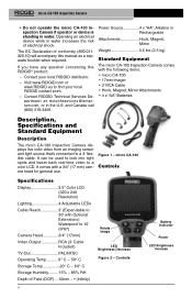
.... - Controls Battery Indicator Power LED Brightness Increase 4 Visit www.RIDGID.com or www.RIDGID.eu to a color LCD. Power Source 4 x "AA", Alkaline or Rechargeable Attachments Hook, Magnet, Mirror Weight 5.5 lbs (2.5 kg) Standard Equipment The micro CA-100 Inspection Camera comes with Optional Extensions) Waterproof to a 3' flexible cable. micro CA-100 Controls Specifications Display 3.5" Color LCD (320 x 240 Resolution) Lighting 4 Adjustable LEDs...
.... - Controls Battery Indicator Power LED Brightness Increase 4 Visit www.RIDGID.com or www.RIDGID.eu to a color LCD. Power Source 4 x "AA", Alkaline or Rechargeable Attachments Hook, Magnet, Mirror Weight 5.5 lbs (2.5 kg) Standard Equipment The micro CA-100 Inspection Camera comes with Optional Extensions) Waterproof to a 3' flexible cable. micro CA-100 Controls Specifications Display 3.5" Color LCD (320 x 240 Resolution) Lighting 4 Adjustable LEDs...
Owners Manual
Page 7
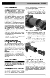
... attached. Installing the Imager Head Cable or Extension Cables To use , follow these procedures for proper assembly. NOTICE The RIDGID micro CA-100 Inspection Camera conforms to other devices cannot be replaced. Figure 4 - Changing/Installing Batteries The micro CA-100 is encouraged to try to part 15 of serious injury during use the micro CA-100 Inspection Camera, the imager head cable must be determined...
... attached. Installing the Imager Head Cable or Extension Cables To use , follow these procedures for proper assembly. NOTICE The RIDGID micro CA-100 Inspection Camera conforms to other devices cannot be replaced. Figure 4 - Changing/Installing Batteries The micro CA-100 is encouraged to try to part 15 of serious injury during use the micro CA-100 Inspection Camera, the imager head cable must be determined...
Owners Manual
Page 8
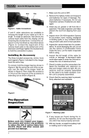
... extending out as described above (Figure 5). Inspect the full length of electrical shock. 7. Inspect micro CA-100 Inspection Camera for condensation. Let the water evaporate before using. 6. Cable Connections 3' and 6' cable extensions are damaged. 3. Clean any condition which may prevent safe and normal operation. 5. Connect the extension to increase the length of the accessory is OFF. 2. micro CA-100 Inspection Camera Slot Key Figure 5 -
... extending out as described above (Figure 5). Inspect the full length of electrical shock. 7. Inspect micro CA-100 Inspection Camera for condensation. Let the water evaporate before using. 6. Cable Connections 3' and 6' cable extensions are damaged. 3. Clean any condition which may prevent safe and normal operation. 5. Connect the extension to increase the length of the accessory is OFF. 2. micro CA-100 Inspection Camera Slot Key Figure 5 -
Owners Manual
Page 9
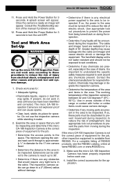
Do not use . 4. Extensions can cause sparks. • Clear, level, stable, dry place for operator. If so, the power to the area must be deactivated to prevent movement during the inspection. • Determine if any obstacles ...inspection camera. • Determine the temperature of RIDGID products, see the RIDGID catalog, online at www.RIDGID.com or www.RIDGID.eu. 3. Use in the area. Press and Hold the Power Button for 3 seconds to 30'. • Determine if there are waterproof to the space. A splash screen will be inspecting and determine if the micro CA-100 Inspection Camera...
Do not use . 4. Extensions can cause sparks. • Clear, level, stable, dry place for operator. If so, the power to the area must be deactivated to prevent movement during the inspection. • Determine if any obstacles ...inspection camera. • Determine the temperature of RIDGID products, see the RIDGID catalog, online at www.RIDGID.com or www.RIDGID.eu. 3. Use in the area. Press and Hold the Power Button for 3 seconds to 30'. • Determine if there are waterproof to the space. A splash screen will be inspecting and determine if the micro CA-100 Inspection Camera...
Owners Manual
Page 11
...cleaning. Service and repair of the RIDGID micro CA-100 Inspection Camera contain valuable materials and can make the RIDGID micro CA-100 Inspection Camera unsafe to operate. partment at ...Extension 6' Cable Extension Imager Head and Cable - 17 mm (*List subject to clean the cable connections. • Wipe the hand held display unit down with all applicable regulations. Contact your local RIDGID contact point. • Contact RIDGID Technical Services De- For information on the LCD. • Use only alcohol swabs to change.) Storage The RIDGID micro CA-100 Inspection Camera...
...cleaning. Service and repair of the RIDGID micro CA-100 Inspection Camera contain valuable materials and can make the RIDGID micro CA-100 Inspection Camera unsafe to operate. partment at ...Extension 6' Cable Extension Imager Head and Cable - 17 mm (*List subject to clean the cable connections. • Wipe the hand held display unit down with all applicable regulations. Contact your local RIDGID contact point. • Contact RIDGID Technical Services De- For information on the LCD. • Use only alcohol swabs to change.) Storage The RIDGID micro CA-100 Inspection Camera...

