
Owners Manual
Page 3
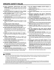
... rotating wheel. n DO NOT OVERREACH. n USE RECOMMENDED ACCESSORIES. Consult this power tool requires that are NOT safety glasses. n CHECK DAMAGED PARTS. Make sure your hand and frees both hands to do the job better and safer at all tools should wear safety glasses and be disconnected. n DO NOT ABUSE CORD. n STAY ALERT AND EXERCISE CONTROL. Read and understand all instructions listed below, may affect operation. n KEEP GUARDS...
... rotating wheel. n DO NOT OVERREACH. n USE RECOMMENDED ACCESSORIES. Consult this power tool requires that are NOT safety glasses. n CHECK DAMAGED PARTS. Make sure your hand and frees both hands to do the job better and safer at all tools should wear safety glasses and be disconnected. n DO NOT ABUSE CORD. n STAY ALERT AND EXERCISE CONTROL. Read and understand all instructions listed below, may affect operation. n KEEP GUARDS...
Owners Manual
Page 4
... by power sanding, sawing, grinding, drilling, and other reproductive harm. n ALWAYS TURN OFF SAW before first use them these instructions also. ALWAYS make sure you check and adjust blade guide settings before disconnecting it to avoid accidental starting a cut . n BEFORE MAKING A CUT, BE SURE ALL ADJUSTMENTS ARE SECURE. n NEVER START THE TOOL when the blade is approximately waist height. To reduce your hand to move into a blade or cutter against the direction...
... by power sanding, sawing, grinding, drilling, and other reproductive harm. n ALWAYS TURN OFF SAW before first use them these instructions also. ALWAYS make sure you check and adjust blade guide settings before disconnecting it to avoid accidental starting a cut . n BEFORE MAKING A CUT, BE SURE ALL ADJUSTMENTS ARE SECURE. n NEVER START THE TOOL when the blade is approximately waist height. To reduce your hand to move into a blade or cutter against the direction...
Owners Manual
Page 6
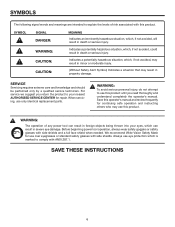
...is marked to explain the levels of any power tool can result in death or serious injury. SAVE THESE INSTRUCTIONS 6 Before beginning power tool operation, always wear safety goggles or safety glasses with side shields. Always use this product. When servicing, use this operator's manual and review frequently for repair. Save this product. Indicates a potentially ...potentially hazardous situation, which , if not avoided, may result in minor or moderate injury. (Without Safety Alert Symbol) Indicates a situation that may use only identical replacement parts.
...is marked to explain the levels of any power tool can result in death or serious injury. SAVE THESE INSTRUCTIONS 6 Before beginning power tool operation, always wear safety goggles or safety glasses with side shields. Always use this product. When servicing, use this operator's manual and review frequently for repair. Save this product. Indicates a potentially ...potentially hazardous situation, which , if not avoided, may result in minor or moderate injury. (Without Safety Alert Symbol) Indicates a situation that may use only identical replacement parts.
Owners Manual
Page 7
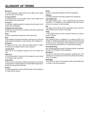
.... Set The distance that area which will be or has been cut without the workpiece properly supported on which the workpiece rests while performing a cutting or sanding operation. 7 Crosscut A cutting or shaping operation made using a miter angle and a bevel angle at any angle to as a workpiece being dropped into the cutting tool first. Usually associated with the blade. Through Sawing Any cutting operation where the blade extends completely through the saw table. Freehand...
.... Set The distance that area which will be or has been cut without the workpiece properly supported on which the workpiece rests while performing a cutting or sanding operation. 7 Crosscut A cutting or shaping operation made using a miter angle and a bevel angle at any angle to as a workpiece being dropped into the cutting tool first. Usually associated with the blade. Through Sawing Any cutting operation where the blade extends completely through the saw table. Freehand...
Owners Manual
Page 8
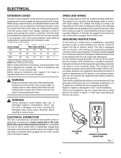
... repair or replacement of electric shock. This tool is designed for a greater distance. It also has a grounding pin like the one power tool may not be too light for outside use tool with a qualified electrician or service personnel if the grounding instructions are working area. ELECTRICAL CONNECTION This tool is as important as to support two or three tools. WARNING: Keep the extension cord clear of power and the motor...
... repair or replacement of electric shock. This tool is designed for a greater distance. It also has a grounding pin like the one power tool may not be too light for outside use tool with a qualified electrician or service personnel if the grounding instructions are working area. ELECTRICAL CONNECTION This tool is as important as to support two or three tools. WARNING: Keep the extension cord clear of power and the motor...
Owners Manual
Page 9
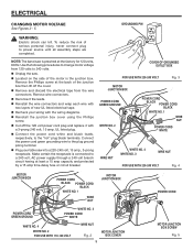
... volt power cord plug and replace it with the wiring diagrams. n Reinstall the junction box cover using the Phillips screw. n Reconnect the leads. Make certain the receptacle is the junction box. ELECTRICAL CHANGING MOTOR VOLTAGE See Figures 2 - 5. Connect the power cord green grounding wire to the "hot" plug blade terminals. Use the following procedures to 240 volts. n Remove and discard the electrical tape from 120 volts to change motor voltage from the wire...
... volt power cord plug and replace it with the wiring diagrams. n Reinstall the junction box cover using the Phillips screw. n Reconnect the leads. Make certain the receptacle is the junction box. ELECTRICAL CHANGING MOTOR VOLTAGE See Figures 2 - 5. Connect the power cord green grounding wire to the "hot" plug blade terminals. Use the following procedures to 240 volts. n Remove and discard the electrical tape from 120 volts to change motor voltage from the wire...
Owners Manual
Page 11
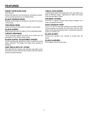
... bearings support the back of the adjustable blade. BLADE HANGERS Extra blades may be tilted at different angles. BLADE GUARD ADJUSTMENT KNOBS Use the blade guide adjustment knobs to clean out sawdust build-up. FEATURES KNOW YOUR BAND SAW See Figure 6. Ensures saw table to the dust exhaust port when using a dust collection system or wet/dry vac. HOUSING COVERS Pull knob to expose wheels during blade changes or to adjust the blade guide assembly. Attach to measure angular settings.
... bearings support the back of the adjustable blade. BLADE HANGERS Extra blades may be tilted at different angles. BLADE GUARD ADJUSTMENT KNOBS Use the blade guide adjustment knobs to clean out sawdust build-up. FEATURES KNOW YOUR BAND SAW See Figure 6. Ensures saw table to the dust exhaust port when using a dust collection system or wet/dry vac. HOUSING COVERS Pull knob to expose wheels during blade changes or to adjust the blade guide assembly. Attach to measure angular settings.
Owners Manual
Page 13
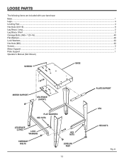
LOOSE PARTS The following items are included with your band saw: Base ...1 Legs...4 Leveling Feet ...4 Hex Nuts (3/8-16) ...8 Leg Brace, Long ...2 Leg Brace, Short ...2 Carriage Bolts, (M8 x 1.25-16) ...40 Flat Washers...40 Lock Washers...40 Hex Nuts (M8)...40 Screws...2 Motor Support ...1 Plate Support ...1 Operator's Manual (Not Shown) SCREWS BASE MOTOR SUPPORT LEG BRACE (SHORT) FLAT WASHERS HEX NUTS LEG BRACE (LONG) LOCK WASHERS CARRIAGE BOLTS HEX NUTS LEVELING FEET 13 PLATE SUPPORT LEG HEX NUTS Fig. 8
LOOSE PARTS The following items are included with your band saw: Base ...1 Legs...4 Leveling Feet ...4 Hex Nuts (3/8-16) ...8 Leg Brace, Long ...2 Leg Brace, Short ...2 Carriage Bolts, (M8 x 1.25-16) ...40 Flat Washers...40 Lock Washers...40 Hex Nuts (M8)...40 Screws...2 Motor Support ...1 Plate Support ...1 Operator's Manual (Not Shown) SCREWS BASE MOTOR SUPPORT LEG BRACE (SHORT) FLAT WASHERS HEX NUTS LEG BRACE (LONG) LOCK WASHERS CARRIAGE BOLTS HEX NUTS LEVELING FEET 13 PLATE SUPPORT LEG HEX NUTS Fig. 8
Owners Manual
Page 15
... operate this tool until they are replaced. If shipping has influenced the settings, refer to power supply until you have carefully inspected the tool, identified all unpainted metal surfaces. n If any ordinary household type grease and spot remover. Any such alteration or modification is heavy. ASSEMBLY UNPACKING This product requires assembly. To avoid back injury, lift with this manual. CARRIAGE BOLT WASHERS LOCK WASHERS...
... operate this tool until they are replaced. If shipping has influenced the settings, refer to power supply until you have carefully inspected the tool, identified all unpainted metal surfaces. n If any ordinary household type grease and spot remover. Any such alteration or modification is heavy. ASSEMBLY UNPACKING This product requires assembly. To avoid back injury, lift with this manual. CARRIAGE BOLT WASHERS LOCK WASHERS...

Owners Manual
Page 20
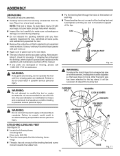
... head screws, (M5 x 0.8-15) 2 washers, (M5) 2 hex nuts, (M5 x 0.8) 1 bevel scale 1 saw table n Align bevel scale on the inside edge of the saw table back and place table screws into the trunnion support. Insert the screws through slot in the scale indicator and into trunnion support. n R� otate saw table with blade installed. n Locate the following items: 1 saw table 2 lock knobs n To mount saw blade through the table and bevel scale as shown. Tighten. Rotate saw table 90° and guide saw table, remove throat plate and pull table pin...
... head screws, (M5 x 0.8-15) 2 washers, (M5) 2 hex nuts, (M5 x 0.8) 1 bevel scale 1 saw table n Align bevel scale on the inside edge of the saw table back and place table screws into the trunnion support. Insert the screws through slot in the scale indicator and into trunnion support. n R� otate saw table with blade installed. n Locate the following items: 1 saw table 2 lock knobs n To mount saw blade through the table and bevel scale as shown. Tighten. Rotate saw table 90° and guide saw table, remove throat plate and pull table pin...
Owners Manual
Page 21
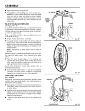
... spring. Before operating, check all screws, bolts and nuts to tension blade. ASSEMBLY n Replace throat plate and table pin. n Turn blade tension knob clockwise to make sure they are snug. Sound should be made at anytime. Changes in the center. Blade must be a musical note. n Transportation and handling may find it necessary to track toward rear of the wheel. n Tighten nut after reading the entire operator's manual including blade tracking, blade guide adjustments, and safety rules. Using...
... spring. Before operating, check all screws, bolts and nuts to tension blade. ASSEMBLY n Replace throat plate and table pin. n Turn blade tension knob clockwise to make sure they are snug. Sound should be made at anytime. Changes in the center. Blade must be a musical note. n Transportation and handling may find it necessary to track toward rear of the wheel. n Tighten nut after reading the entire operator's manual including blade tracking, blade guide adjustments, and safety rules. Using...
Owners Manual
Page 23
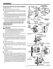
... spring, remove blade guard adjustment knob, tighten or loosen set screw until the overlap is reached, and replace blade guard adjustment knob. WARNING: Blade guard has been removed for picture clarity. Never operate the band saw teeth. n Blade must already be adjusted so that the back edge of the blade overlaps the front face of the saw without pinching it. The thickness of thumb. n Loosen thumb screw and turn knurled knob to just above the material being cut. n Tighten...
... spring, remove blade guard adjustment knob, tighten or loosen set screw until the overlap is reached, and replace blade guard adjustment knob. WARNING: Blade guard has been removed for picture clarity. Never operate the band saw teeth. n Blade must already be adjusted so that the back edge of the blade overlaps the front face of the saw without pinching it. The thickness of thumb. n Loosen thumb screw and turn knurled knob to just above the material being cut. n Tighten...
Owners Manual
Page 24
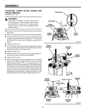
... overlap between the bearing face and the blade. Reinstall the bearing shaft, the bearing, and the screw. THUMB SCREW SAW BLADE KNURLED KNOB BEARING SCREW 24 BEARING SHAFT Fig. 36 ASSEMBLY ADJUSTING LOWER BLADE GUIDES AND THRUST BEARING See Figures 35 - 36. WARNING: Saw table in . Failure to blade as close to do so could result in working order. n Disconnect machine from the power source and remove switch key.
... overlap between the bearing face and the blade. Reinstall the bearing shaft, the bearing, and the screw. THUMB SCREW SAW BLADE KNURLED KNOB BEARING SCREW 24 BEARING SHAFT Fig. 36 ASSEMBLY ADJUSTING LOWER BLADE GUIDES AND THRUST BEARING See Figures 35 - 36. WARNING: Saw table in . Failure to blade as close to do so could result in working order. n Disconnect machine from the power source and remove switch key.
Owners Manual
Page 25
... screwdriver or wooden wedge. WARNING: To avoid blade contact, adjust the blade guide assembly to a full and complete stop immediately. Failure to cut . If you careless. Do not restart until the saw table. CUTTING PROCEDURES n Hold the workpiece firmly against the saw . Do not force the work into the blade. a 1/8 in the OFF (O) position then remove the switch key from the blade. n Keep your hands away from the switch assembly. n Use extra supports (tables, saw...
... screwdriver or wooden wedge. WARNING: To avoid blade contact, adjust the blade guide assembly to a full and complete stop immediately. Failure to cut . If you careless. Do not restart until the saw table. CUTTING PROCEDURES n Hold the workpiece firmly against the saw . Do not force the work into the blade. a 1/8 in the OFF (O) position then remove the switch key from the blade. n Keep your hands away from the switch assembly. n Use extra supports (tables, saw...
Owners Manual
Page 26
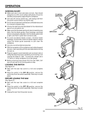
... pieces until the saw on a firm, level surface with plenty of room for the material and type of the workpiece and related support devises, clear everything off the saw table before moving the saw off , remove switch key, and unplug cord from the saw table, turn saw . LOCKING THE SWITCH See Figure 37. OPERATION AVOIDING INJURY n Make sure saw table, that the blade guides, thrust bearings, and blade tension are properly adjusted, that no parts...
... pieces until the saw on a firm, level surface with plenty of room for the material and type of the workpiece and related support devises, clear everything off the saw table before moving the saw off , remove switch key, and unplug cord from the saw table, turn saw . LOCKING THE SWITCH See Figure 37. OPERATION AVOIDING INJURY n Make sure saw table, that the blade guides, thrust bearings, and blade tension are properly adjusted, that no parts...
Owners Manual
Page 29
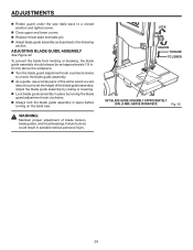
... blade guide assembly by turning the blade guard adjustment knob clockwise. Failure to unlock the blade guide assembly. n Turn the blade guard adjustment knob counterclockwise to do so could result in . (3 mm) above the workpiece. n Always lock the blade guide assembly in place before turning on the band saw table back to set approximately 1/8 in possible serious personal injury. n Lock blade guide assembly in the following section. n Replace throat plate and table pin. WARNING: Maintain proper adjustment of the blade guide assembly. ADJUSTMENTS n Rotate guard under the saw...
... blade guide assembly by turning the blade guard adjustment knob clockwise. Failure to unlock the blade guide assembly. n Turn the blade guard adjustment knob counterclockwise to do so could result in . (3 mm) above the workpiece. n Always lock the blade guide assembly in place before turning on the band saw table back to set approximately 1/8 in possible serious personal injury. n Lock blade guide assembly in the following section. n Replace throat plate and table pin. WARNING: Maintain proper adjustment of the blade guide assembly. ADJUSTMENTS n Rotate guard under the saw...
Owners Manual
Page 30
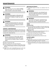
... tire around the wheel. They contain chemicals that could result in serious personal injury. WARNING: If the power cord is dusty, also wear a dust mask. Replacing Tires: n Open front cover and remove saw clean. Use clean cloths to do so could cause possible serious personal injury, turn off the saw, remove the switch key, and unplug the saw table, blade guides, or thrust bearings. MOTOR/ELECTRICAL n Frequently vacuum or...
... tire around the wheel. They contain chemicals that could result in serious personal injury. WARNING: If the power cord is dusty, also wear a dust mask. Replacing Tires: n Open front cover and remove saw clean. Use clean cloths to do so could cause possible serious personal injury, turn off the saw, remove the switch key, and unplug the saw table, blade guides, or thrust bearings. MOTOR/ELECTRICAL n Frequently vacuum or...
Owners Manual
Page 32
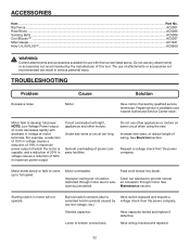
... to saw . Have wiring checked and repaired. 32 ACCESSORIES Item ...Part No. Feed work slower into blade. Burned switch contacts (due to provide normal restricted through motor. Starting switch in periods caused by qualified service technician. Loose or broken connections. Increase wire sizes, or reduce length of power company facilities. Request a voltage check from the power company. See Electrical section. Shorted capacitor. Do not use of this tool are listed...
... to saw . Have wiring checked and repaired. 32 ACCESSORIES Item ...Part No. Feed work slower into blade. Burned switch contacts (due to provide normal restricted through motor. Starting switch in periods caused by qualified service technician. Loose or broken connections. Increase wire sizes, or reduce length of power company facilities. Request a voltage check from the power company. See Electrical section. Shorted capacitor. Do not use of this tool are listed...
Owners Manual
Page 33
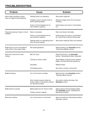
.... Starting switch not operating (motor Have switch replaced. Band Saw slows down , trying to reach operating speed. Stop feeding, and back up . Kink in blown fuses or tripped circuit breakers). Blade guides set too close to "Mounting the Motor Assembly" section. 33 See Assembly section "Installing and Adjusting the blade". TROUBLESHOOTING Problem Motor stalls (resulting in blade caused cutting too small a radius or turning the material too fast when cutting. Check that wiring will handle load. Overloading motor. Adjust belt tension, see Assembly section...
.... Starting switch not operating (motor Have switch replaced. Band Saw slows down , trying to reach operating speed. Stop feeding, and back up . Kink in blown fuses or tripped circuit breakers). Blade guides set too close to "Mounting the Motor Assembly" section. 33 See Assembly section "Installing and Adjusting the blade". TROUBLESHOOTING Problem Motor stalls (resulting in blade caused cutting too small a radius or turning the material too fast when cutting. Check that wiring will handle load. Overloading motor. Adjust belt tension, see Assembly section...
Owners Manual
Page 35
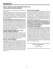
... date of the tool. To receive a replacement tool you must return it was purchased for RIDGID® branded hand held and stationary power tools. HOW TO OBTAIN SERVICE To obtain service for this RIDGID® tool you must present proof of purchase and return all original equipment packaged with the tool such as brushes, chucks, motors, switches, cords, gears and even cordless batteries in to an authorized service center for a full...
... date of the tool. To receive a replacement tool you must return it was purchased for RIDGID® branded hand held and stationary power tools. HOW TO OBTAIN SERVICE To obtain service for this RIDGID® tool you must present proof of purchase and return all original equipment packaged with the tool such as brushes, chucks, motors, switches, cords, gears and even cordless batteries in to an authorized service center for a full...


