Warranty Card
Page 1
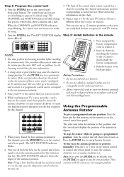
... hold the INITIAL and > keys (make sure you may not apply to keep the antenna positions and program locations synchronized. Release the D key and turn the control unit back on the front panel reads 0, and the ANT POSITION display reads 00. Turn the unit back on the control unit's front panel. 3. dated bill of sale), specification of different battery types (e.g. This Warranty does...
... hold the INITIAL and > keys (make sure you may not apply to keep the antenna positions and program locations synchronized. Release the D key and turn the control unit back on the front panel reads 0, and the ANT POSITION display reads 00. Turn the unit back on the control unit's front panel. 3. dated bill of sale), specification of different battery types (e.g. This Warranty does...
Owner/User Manual
Page 1
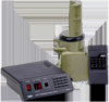
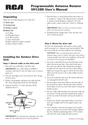
... far as they leave just enough room for the support mast to 280' (84m) of the drive unit base. Put the largest of the four brackets onto the ends of the top two inserts. Programmable Antenna Rotator VH126N User's Manual Unpacking Make sure the following pieces are in the box: (1) Drive unit (1) Control unit (1) Remote control Hardware kit: (2) U Bolts (4) Threaded inserts (3) U Bolt brackets (1) Guy wire bracket (8) Nuts with power...
... far as they leave just enough room for the support mast to 280' (84m) of the drive unit base. Put the largest of the four brackets onto the ends of the top two inserts. Programmable Antenna Rotator VH126N User's Manual Unpacking Make sure the following pieces are in the box: (1) Drive unit (1) Control unit (1) Remote control Hardware kit: (2) U Bolts (4) Threaded inserts (3) U Bolt brackets (1) Guy wire bracket (8) Nuts with power...
Owner/User Manual
Page 2
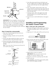
... the front panel reads 0, and the ANT POSITION display reads 00. Strip about 1/2" of the lower bracket. Insert each of the two holes of the jacket off Antenna lead-in place. 4. IMPORTANT: The unit must be used , fasten two through each bare wire into AC outlet. 6. Plug power cord of cable needed to mast Support mast 4. Turn on connector. The CHANNEL on the control unit's back panel as shown...
... the front panel reads 0, and the ANT POSITION display reads 00. Strip about 1/2" of the lower bracket. Insert each of the two holes of the jacket off Antenna lead-in place. 4. IMPORTANT: The unit must be used , fasten two through each bare wire into AC outlet. 6. Plug power cord of cable needed to mast Support mast 4. Turn on connector. The CHANNEL on the control unit's back panel as shown...
Owner/User Manual
Page 3
... installing the antenna mast. Choose a different letter key to re-synchronize the system. Tune your TV screen, press the < and > keys on the control unit's front panel to move the antenna clockwise (>) and counter-clockwise ( or < keys on the antenna mast. When the CHANNEL and POSITION indicators stops blinking, the control unit and rotator are initializing to make sure the rotator goes the entire 360º with no problems...
... installing the antenna mast. Choose a different letter key to re-synchronize the system. Tune your TV screen, press the < and > keys on the control unit's front panel to move the antenna clockwise (>) and counter-clockwise ( or < keys on the antenna mast. When the CHANNEL and POSITION indicators stops blinking, the control unit and rotator are initializing to make sure the rotator goes the entire 360º with no problems...

Owner/User Manual
Page 4
... Audiovox Accessories Corporation 111 Congressional Blvd., Suite 350 Carmel, IN 46032 VH126N US IB 00 Trademark(s) ® Registered Made in connection with the product. To obtain repair or replacement within 12 months from state/ province to keep the antenna positions and program locations synchronized. This Warranty does not cover damage caused by an AC adapter not provided with the sale...
... Audiovox Accessories Corporation 111 Congressional Blvd., Suite 350 Carmel, IN 46032 VH126N US IB 00 Trademark(s) ® Registered Made in connection with the product. To obtain repair or replacement within 12 months from state/ province to keep the antenna positions and program locations synchronized. This Warranty does not cover damage caused by an AC adapter not provided with the sale...
Owner/User Manual
Page 5
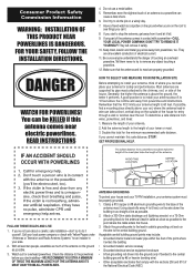
.... Most antennas are supported by #6 or heavier bonding wire) • Other acceptable electrodes that the antenna and its mast are all excellent conductors of touching an overhead powerline. If you start to the central building ground. Using stand-offs every 4 to 6 feet, run the wire to drop the antenna, get away from powerlines and obstructions. If possible, find a mounting place directly above the...
.... Most antennas are supported by #6 or heavier bonding wire) • Other acceptable electrodes that the antenna and its mast are all excellent conductors of touching an overhead powerline. If you start to the central building ground. Using stand-offs every 4 to 6 feet, run the wire to drop the antenna, get away from powerlines and obstructions. If possible, find a mounting place directly above the...


