
User Manual
Page 2
... and check immediately for the cause. (e) When practical, remove gas-powered equipment Vibration is highly flammable (f) Keep the nozzle in moving parts. it is generally a warning of trouble. Exercise extreme caution when operating on or cross- (b) Never add fuel to a running (except...position, before unclogging the collector/impeller housing or discharge chute, and when making repairs. WARNING: Snow throwers have exposed rotating parts, which can get caught in contact with the rim of California to be exercised while using on sloping surfaces. WARNING: ...
... and check immediately for the cause. (e) When practical, remove gas-powered equipment Vibration is highly flammable (f) Keep the nozzle in moving parts. it is generally a warning of trouble. Exercise extreme caution when operating on or cross- (b) Never add fuel to a running (except...position, before unclogging the collector/impeller housing or discharge chute, and when making repairs. WARNING: Snow throwers have exposed rotating parts, which can get caught in contact with the rim of California to be exercised while using on sloping surfaces. WARNING: ...
User Manual
Page 3
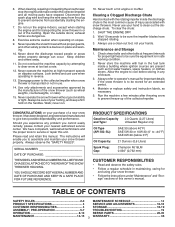
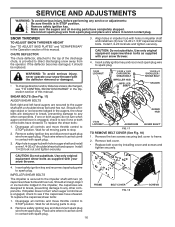
When cleaning, repairing or inspecting the snow thrower, stop the engine and make certain the collector/impeller and all moving parts have stopped rotating. 3. Disconnect the spark plug wire and keep a firm hold on your nearest authorized service center....14 PRODUCT SPECIFICATIONS 4 SERVICE AND ADJUSTMENTS 16-18 CUSTOMER RESPONSIBILITIES 4 STORAGE 18-19 ASSEMBLY / PRE-OPERATION 5-7 TROUBLESHOOTING 19 OPERATION 8-13 REPAIR PARTS 20-35 MAINTENANCE 14-15 3 WARRANTY 36 Walk; Never store the machine with fuel in any problem you to be sure of your footing...
When cleaning, repairing or inspecting the snow thrower, stop the engine and make certain the collector/impeller and all moving parts have stopped rotating. 3. Disconnect the spark plug wire and keep a firm hold on your nearest authorized service center....14 PRODUCT SPECIFICATIONS 4 SERVICE AND ADJUSTMENTS 16-18 CUSTOMER RESPONSIBILITIES 4 STORAGE 18-19 ASSEMBLY / PRE-OPERATION 5-7 TROUBLESHOOTING 19 OPERATION 8-13 REPAIR PARTS 20-35 MAINTENANCE 14-15 3 WARRANTY 36 Walk; Never store the machine with fuel in any problem you to be sure of your footing...
User Manual
Page 4
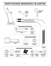
PARTS PACKED SEPARATELY IN CARTON (1) MULTIWRENCH (180684) (3) RETAINER SPRINGS (169675) (1) DISCHARGE CHUTE (1) AUGER CONTROL ROD (1) TRACTION DRIVE CONTROL ROD EXTRA SHEAR BOLTS AND NUTS (2) SHEAR BOLTS 1/4-...
PARTS PACKED SEPARATELY IN CARTON (1) MULTIWRENCH (180684) (3) RETAINER SPRINGS (169675) (1) DISCHARGE CHUTE (1) AUGER CONTROL ROD (1) TRACTION DRIVE CONTROL ROD EXTRA SHEAR BOLTS AND NUTS (2) SHEAR BOLTS 1/4-...
User Manual
Page 5
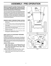
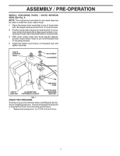
...PRE-OPERATION Read these instructions and this manual in its entirety before you attempt to complete the assembly have been placed in the parts bag. All parts such as necessary to the pallet. 4. UPPER HANDLE HANDLE KNOB SPEED CONTROL ROD PLASTIC TIE REMOVE SNOW THROWER FROM CARTON 1. ... has been assembled at the factory with retainer spring. NOTE: The multi-wrench may be tightened securely. Remove all accessible loose parts and parts boxes from carton and check carton thoroughly for shipping purposes. Additional carriage bolts, washers and handle knobs are in assembly, operation ...
...PRE-OPERATION Read these instructions and this manual in its entirety before you attempt to complete the assembly have been placed in the parts bag. All parts such as necessary to the pallet. 4. UPPER HANDLE HANDLE KNOB SPEED CONTROL ROD PLASTIC TIE REMOVE SNOW THROWER FROM CARTON 1. ... has been assembled at the factory with retainer spring. NOTE: The multi-wrench may be tightened securely. Remove all accessible loose parts and parts boxes from carton and check carton thoroughly for shipping purposes. Additional carriage bolts, washers and handle knobs are in assembly, operation ...
User Manual
Page 7
... HEAD (See Fig. 7) NOTE: The multi-wrench provided in chute bracket. 3. With chute rotator head and chute bracket aligned, position chute rotator head on your parts bag may be used to align square and pin on threaded stud and tighten securely. Install 3/8 washer and locknut on underside of chute rotator head...
... HEAD (See Fig. 7) NOTE: The multi-wrench provided in chute bracket. 3. With chute rotator head and chute bracket aligned, position chute rotator head on your parts bag may be used to align square and pin on threaded stud and tighten securely. Install 3/8 washer and locknut on underside of chute rotator head...

User Manual
Page 10
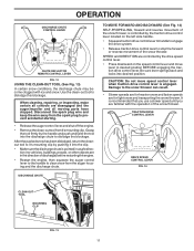
... position. SLOW FIG. 10 10 NOTE: Never use . OFF FULL FIG. 11 TO CONTROL SNOW DISCHARGE (See Fig. 12) WARNING: Snow throwers have exposed rotating parts, which can cause severe injury from contact, or from material thrown from the discharge chute. OPERATION The operation of any adjustments or repairs. OFF OPEN... HANDS, to throw snow a short distance; STOPPING TRACTION DRIVE • Release traction drive control lever to stop the forward or reverse movement of all moving parts to start the engine. Do not use to stop throwing snow.
... position. SLOW FIG. 10 10 NOTE: Never use . OFF FULL FIG. 11 TO CONTROL SNOW DISCHARGE (See Fig. 12) WARNING: Snow throwers have exposed rotating parts, which can cause severe injury from contact, or from material thrown from the discharge chute. OPERATION The operation of any adjustments or repairs. OFF OPEN... HANDS, to throw snow a short distance; STOPPING TRACTION DRIVE • Release traction drive control lever to stop the forward or reverse movement of all moving parts to start the engine. Do not use to stop throwing snow.
User Manual
Page 11
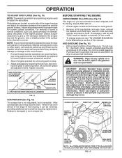
... DRIVE SPEED CONTROL LEVER FIG. 14 DISCHARGE CHUTE CLEAN-OUT TOOL MOUNTING CLIP FIG. 13 11 When cleaning, repairing, or inspecting, make certain all moving parts have stopped. Damage to desired position BEFORE engaging the traction drive control lever. SPEED and DIRECTION are familiar with ice and snow. CAUTION: Do not...
... DRIVE SPEED CONTROL LEVER FIG. 14 DISCHARGE CHUTE CLEAN-OUT TOOL MOUNTING CLIP FIG. 13 11 When cleaning, repairing, or inspecting, make certain all moving parts have stopped. Damage to desired position BEFORE engaging the traction drive control lever. SPEED and DIRECTION are familiar with ice and snow. CAUTION: Do not...
User Manual
Page 12
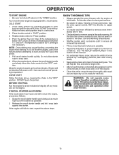
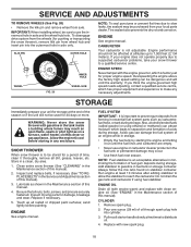
... almost to the edge of the housing, it can damage the fuel system of acids during storage. Check engine oil with snow thrower on your parts bag may be used within 30 days to assure fuel freshness. If necessary, add oil until the fuel lines and carburetor are adjusted to bottom... snow in normal conditions, such as gravel, rocks or other debris, can easily be picked up and thrown by loosening the hex nuts, then moving parts to adjust the skid plates. ACTUAL LOCATION MAY VARY WITH ENGINE ON YOUR UNIT. 12 FIG. 16 Adjust skid plates by the impeller, which leads...
... almost to the edge of the housing, it can damage the fuel system of acids during storage. Check engine oil with snow thrower on your parts bag may be used within 30 days to assure fuel freshness. If necessary, add oil until the fuel lines and carburetor are adjusted to bottom... snow in normal conditions, such as gravel, rocks or other debris, can easily be picked up and thrown by loosening the hex nuts, then moving parts to adjust the skid plates. ACTUAL LOCATION MAY VARY WITH ENGINE ON YOUR UNIT. 12 FIG. 16 Adjust skid plates by the impeller, which leads...
User Manual
Page 13
.... Place throttle control in a safe place. 2. Push the primer four (4) times if the temperature is below 15°F, or two (2) times if temperature is in parts bag) into ignition slot until it has reached normal operating temperature. NOTE: Over priming may cause flooding, preventing the engine from starting. DO NOT push...
.... Place throttle control in a safe place. 2. Push the primer four (4) times if the temperature is below 15°F, or two (2) times if temperature is in parts bag) into ignition slot until it has reached normal operating temperature. NOTE: Over priming may cause flooding, preventing the engine from starting. DO NOT push...
User Manual
Page 14
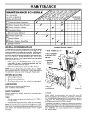
...corrosion. 14 the snow thrower. Check engine oil level. 2. Check controls to be made periodically to properly maintain your snow thrower. Using other parts dealer. Some adjustments will help your engine run better and last longer. • Follow the maintenance schedule in this manual. LUBRICATION CHART SAE...in this manual). • Keep tires free of gasoline and oil, which can harm rubber. NOTE: Use only Original Equipment Manufacturer (OEM) parts to service this snow thrower does not cover items that have been subjected to slip from wear. (See "TO REMOVE BELT COVER" in ...
...corrosion. 14 the snow thrower. Check engine oil level. 2. Check controls to be made periodically to properly maintain your snow thrower. Using other parts dealer. Some adjustments will help your engine run better and last longer. • Follow the maintenance schedule in this manual. LUBRICATION CHART SAE...in this manual). • Keep tires free of gasoline and oil, which can harm rubber. NOTE: Use only Original Equipment Manufacturer (OEM) parts to service this snow thrower does not cover items that have been subjected to slip from wear. (See "TO REMOVE BELT COVER" in ...
User Manual
Page 16
... SPACER AUGER HUB 1/4-20 LOCKNUT AUGER HUB AUGER SHAFT FIG. 17 TO REMOVE BELT COVER (See Fig. 18) 1. Make sure the augers and all moving parts to STOP position. If one or both augers do not turn when auger control lever is engaged, check to the impeller shaft with spark plug... safety ignition key. 3. Wait for all controls and move throttle control to any other components. Install 1/4-20 lock nut and tighten securely. 3. Disengage all moving parts have sheared. Wait for all moving...
... SPACER AUGER HUB 1/4-20 LOCKNUT AUGER HUB AUGER SHAFT FIG. 17 TO REMOVE BELT COVER (See Fig. 18) 1. Make sure the augers and all moving parts to STOP position. If one or both augers do not turn when auger control lever is engaged, check to the impeller shaft with spark plug... safety ignition key. 3. Wait for all controls and move throttle control to any other components. Install 1/4-20 lock nut and tighten securely. 3. Disengage all moving parts have sheared. Wait for all moving...
User Manual
Page 18
...HOLE WHEEL FIG. 20 INNER HOLE WHEEL HUB NOTE: To seal punctures or prevent flat tires due to prevent gum deposits from your local parts dealer. If you think the engine-governed high speed needs adjusting, contact a qualified service centre, which has proper equipment and experience to reach...Store in axle only. Inspect and replace belts, if necessary (See "TO REPLACE BELTS" in axle and the wheel hub hole. Inspect moving parts for 30 days or more. Run engine at least 10 minutes after adding stabilizer to allow the stabilizer to make any enclosure. IMPORTANT: When ...
...HOLE WHEEL FIG. 20 INNER HOLE WHEEL HUB NOTE: To seal punctures or prevent flat tires due to prevent gum deposits from your local parts dealer. If you think the engine-governed high speed needs adjusting, contact a qualified service centre, which has proper equipment and experience to reach...Store in axle only. Inspect and replace belts, if necessary (See "TO REPLACE BELTS" in axle and the wheel hub hole. Inspect moving parts for 30 days or more. Run engine at least 10 minutes after adding stabilizer to allow the stabilizer to make any enclosure. IMPORTANT: When ...
User Manual
Page 19
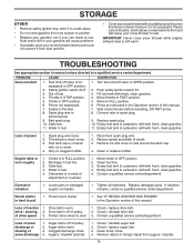
... wire is worn. 3. Stale fuel. 11. Fill fuel tank with fresh, clean gasoline. 11. Wait a few minutes before restarting, DO NOT prime. 8. Replace damaged parts. drive / slowing 2. Friction drive wheel is disconnected. 9. Check / reinstall auger belt. 2. Empty fuel tank & carburetor, refill with fresh, clean gasoline. 4. Loss .... IMPORTANT: Never cover snow thrower while engine/ exhaust area is off of traction 1. store it from augers / impeller. 19 Loose parts or damaged augers or impeller. 1. Move to protect it in manual unless directed to rust.
... wire is worn. 3. Stale fuel. 11. Fill fuel tank with fresh, clean gasoline. 11. Wait a few minutes before restarting, DO NOT prime. 8. Replace damaged parts. drive / slowing 2. Friction drive wheel is disconnected. 9. Check / reinstall auger belt. 2. Empty fuel tank & carburetor, refill with fresh, clean gasoline. 4. Loss .... IMPORTANT: Never cover snow thrower while engine/ exhaust area is off of traction 1. store it from augers / impeller. 19 Loose parts or damaged augers or impeller. 1. Move to protect it in manual unless directed to rust.
User Manual
Page 20
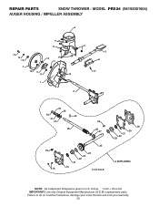
inches. 1 inch = 25.4 mm IMPORTANT: Use only Original Equipment Manufacturer (O.E.M.) replacement parts. MODEL PR524 (96192001504) AUGER HOUSING / IMPELLER ASSEMBLY 5 11 6 15 14 13 4 12 16 11 12 3 11 1 9 10 2 11 7 8 17 33 32 34 30 31 31 29 26 28 27 35 18 25 24 23 22 21 19 01.07.004-B 36 20 21 22 23 2 (EXPLODED) NOTE: All component dimensions given in U.S. Failure to do so could be hazardous, damage your snow thrower and void your warranty. 20 REPAIR PARTS SNOW THROWER -
inches. 1 inch = 25.4 mm IMPORTANT: Use only Original Equipment Manufacturer (O.E.M.) replacement parts. MODEL PR524 (96192001504) AUGER HOUSING / IMPELLER ASSEMBLY 5 11 6 15 14 13 4 12 16 11 12 3 11 1 9 10 2 11 7 8 17 33 32 34 30 31 31 29 26 28 27 35 18 25 24 23 22 21 19 01.07.004-B 36 20 21 22 23 2 (EXPLODED) NOTE: All component dimensions given in U.S. Failure to do so could be hazardous, damage your snow thrower and void your warranty. 20 REPAIR PARTS SNOW THROWER -
User Manual
Page 21
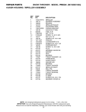
... could be hazardous, damage your snow thrower and void your warranty. 21 inches. 1 inch = 25.4 mm IMPORTANT: Use only Original Equipment Manufacturer (O.E.M.) replacement parts. REPAIR PARTS SNOW THROWER - MODEL PR524 (96192001504) AUGER HOUSING / IMPELLER ASSEMBLY KEY NO. 1 2 3 4 5 6 7 8 9 10 11 12 13 14 15 16 17 18 19 20 21... 22 23 24 25 26 27 28 29 30 31 32 33 34 35 36 PART NO. 175321X479 196710 188909 191079 175322 178675X008 192199 405400 73800400...
... could be hazardous, damage your snow thrower and void your warranty. 21 inches. 1 inch = 25.4 mm IMPORTANT: Use only Original Equipment Manufacturer (O.E.M.) replacement parts. REPAIR PARTS SNOW THROWER - MODEL PR524 (96192001504) AUGER HOUSING / IMPELLER ASSEMBLY KEY NO. 1 2 3 4 5 6 7 8 9 10 11 12 13 14 15 16 17 18 19 20 21... 22 23 24 25 26 27 28 29 30 31 32 33 34 35 36 PART NO. 175321X479 196710 188909 191079 175322 178675X008 192199 405400 73800400...
User Manual
Page 22
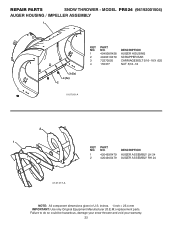
... to do so could be hazardous, damage your snow thrower and void your warranty. 22 REPAIR PARTS SNOW THROWER - MODEL PR524 (96192001504) AUGER HOUSING / IMPELLER ASSEMBLY 1 3 (5x) 4 (5x) 2 01.07.001-A KEY NO. 1 2 3 4 PART NO. 404928X428 404931X479 72270505 155377 DESCRIPTION AUGER HOUSING SCRAPPER BAR CARRIAGE BOLT 5/16−18 X .625 NUT 5/16−...
... to do so could be hazardous, damage your snow thrower and void your warranty. 22 REPAIR PARTS SNOW THROWER - MODEL PR524 (96192001504) AUGER HOUSING / IMPELLER ASSEMBLY 1 3 (5x) 4 (5x) 2 01.07.001-A KEY NO. 1 2 3 4 PART NO. 404928X428 404931X479 72270505 155377 DESCRIPTION AUGER HOUSING SCRAPPER BAR CARRIAGE BOLT 5/16−18 X .625 NUT 5/16−...
User Manual
Page 23
MODEL PR524 (96192001504) AUGER HOUSING / IMPELLER ASSEMBLY 2 3 1 1 2 3 01.07.024-B KEY NO. 1 2 3 PART NO. 420478 411939 179582 DESCRIPTION AUGER BEARING BEARING PLUG SCREW 5/16−18 X 1.00 4 3 01.11.001-A 1 3 4 2 KEY NO. 1 2 3 4 PART NO. 174762X479 178777X479 72270506 751153 DESCRIPTION SKID PLATE LH SKID PLATE RH CARRIAGE ...18 NOTE: All component dimensions given in U.S. inches. 1 inch = 25.4 mm IMPORTANT: Use only Original Equipment Manufacturer (O.E.M.) replacement parts. Failure to do so could be hazardous, damage your snow thrower and void your warranty. 23 REPAIR...
MODEL PR524 (96192001504) AUGER HOUSING / IMPELLER ASSEMBLY 2 3 1 1 2 3 01.07.024-B KEY NO. 1 2 3 PART NO. 420478 411939 179582 DESCRIPTION AUGER BEARING BEARING PLUG SCREW 5/16−18 X 1.00 4 3 01.11.001-A 1 3 4 2 KEY NO. 1 2 3 4 PART NO. 174762X479 178777X479 72270506 751153 DESCRIPTION SKID PLATE LH SKID PLATE RH CARRIAGE ...18 NOTE: All component dimensions given in U.S. inches. 1 inch = 25.4 mm IMPORTANT: Use only Original Equipment Manufacturer (O.E.M.) replacement parts. Failure to do so could be hazardous, damage your snow thrower and void your warranty. 23 REPAIR...
User Manual
Page 24
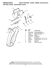
REPAIR PARTS SNOW THROWER - MODEL PR524 (96192001504) CONTROL PANEL / DISCHARGE CHUTE 2 11 3 6 8 6 10 5 9 11 4 11 7 KEY PART NO. NO. inches. 1 inch = 25.4 mm IMPORTANT: Use only Original Equipment Manufacturer (O.E.M.) replacement parts. Failure to do so could be hazardous, damage your snow thrower and void your warranty. 24 DESCRIPTION 1 1 404770X428 CHUTE WELDMENT 2 178633X428 DEFLECTOR WELDMENT 3 420325...
REPAIR PARTS SNOW THROWER - MODEL PR524 (96192001504) CONTROL PANEL / DISCHARGE CHUTE 2 11 3 6 8 6 10 5 9 11 4 11 7 KEY PART NO. NO. inches. 1 inch = 25.4 mm IMPORTANT: Use only Original Equipment Manufacturer (O.E.M.) replacement parts. Failure to do so could be hazardous, damage your snow thrower and void your warranty. 24 DESCRIPTION 1 1 404770X428 CHUTE WELDMENT 2 178633X428 DEFLECTOR WELDMENT 3 420325...
User Manual
Page 25
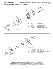
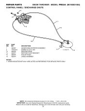
... void your warranty. 25 inches. 1 inch = 25.4 mm IMPORTANT: Use only Original Equipment Manufacturer (O.E.M.) replacement parts. ITEMS INDICATED WITH AN * ARE LISTED AS REFERENCE FOR SERVICE PARTS ONLY. MODEL PR524 (96192001504) CONTROL PANEL / DISCHARGE CHUTE 2 2 *3 1 *6 *6 KEY NO. 1 2 *3 *4 *5 *6 PART NO. 420337 17501010 420678 420677 420675 420674 DESCRIPTION LEVER/CABLE ROTATOR ASSEMBLY SCREW 10−24...
... void your warranty. 25 inches. 1 inch = 25.4 mm IMPORTANT: Use only Original Equipment Manufacturer (O.E.M.) replacement parts. ITEMS INDICATED WITH AN * ARE LISTED AS REFERENCE FOR SERVICE PARTS ONLY. MODEL PR524 (96192001504) CONTROL PANEL / DISCHARGE CHUTE 2 2 *3 1 *6 *6 KEY NO. 1 2 *3 *4 *5 *6 PART NO. 420337 17501010 420678 420677 420675 420674 DESCRIPTION LEVER/CABLE ROTATOR ASSEMBLY SCREW 10−24...
User Manual
Page 26
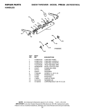
inches. 1 inch = 25.4 mm IMPORTANT: Use only Original Equipment Manufacturer (O.E.M.) replacement parts. MODEL PR524 (96192001504) 10 2 11 9 5 7 6 8 47 9 1 13 8 13 12 14 14 01.08.002-E 12 KEY NO. 1 2 3 4 5 6 7 8 9 10 11 12 13 14 PART NO. 412683X479 412681X479 412682X479 412679X008 420889X008 412677 421613 169675 17060408 414280 414281 178899 19131316 72120618 DESCRIPTION CONTROL PANEL CONTROL...;16 X 2.25 NOTE: All component dimensions given in U.S. Failure to do so could be hazardous, damage your snow thrower and void your warranty. 26 REPAIR PARTS HANDLES 3 SNOW THROWER -
inches. 1 inch = 25.4 mm IMPORTANT: Use only Original Equipment Manufacturer (O.E.M.) replacement parts. MODEL PR524 (96192001504) 10 2 11 9 5 7 6 8 47 9 1 13 8 13 12 14 14 01.08.002-E 12 KEY NO. 1 2 3 4 5 6 7 8 9 10 11 12 13 14 PART NO. 412683X479 412681X479 412682X479 412679X008 420889X008 412677 421613 169675 17060408 414280 414281 178899 19131316 72120618 DESCRIPTION CONTROL PANEL CONTROL...;16 X 2.25 NOTE: All component dimensions given in U.S. Failure to do so could be hazardous, damage your snow thrower and void your warranty. 26 REPAIR PARTS HANDLES 3 SNOW THROWER -


