
User Manual
Page 2
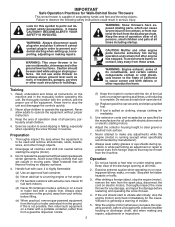
... operating the snow thrower in reverse. (f) Keep the nozzle in serious injury. Do not put hands or feet near or under rotating parts. Keep clear of the discharge opening at all units with a portable container, rather than from the machine. To avoid severe burns on...neutral before starting motors. 6. Exercise extreme caution when operating on a truck or trailer bed with care; WARNING: Snow throwers have exposed rotating parts, which can get caught in the manual(s) before filling. (e) When practical, remove gas-powered equipment from the truck or trailer and refuel...
... operating the snow thrower in reverse. (f) Keep the nozzle in serious injury. Do not put hands or feet near or under rotating parts. Keep clear of the discharge opening at all units with a portable container, rather than from the machine. To avoid severe burns on...neutral before starting motors. 6. Exercise extreme caution when operating on a truck or trailer bed with care; WARNING: Snow throwers have exposed rotating parts, which can get caught in the manual(s) before filling. (e) When practical, remove gas-powered equipment from the truck or trailer and refuel...
User Manual
Page 3
...ASSEMBLY / PRE-OPERATION 4-7 OPERATION 8-13 MAINTENANCE SCHEDULE 14 MAINTENANCE 14-15 SERVICE AND ADJUSTMENTS 16-18 STORAGE 19 TROUBLESHOOTING 20 REPAIR PARTS 21-39 WARRANTY BACK COVER 3 Open the outside doors; Exercise extreme caution when operating on slippery surfaces. Use only attachments and accessories...thrower. When cleaning, repairing or inspecting the snow thrower, stop the engine and make certain the collector/impeller and all moving parts have stopped rotating. 3. Disconnect the spark plug wire and keep a firm hold on the handles. Disengage power to the ...
...ASSEMBLY / PRE-OPERATION 4-7 OPERATION 8-13 MAINTENANCE SCHEDULE 14 MAINTENANCE 14-15 SERVICE AND ADJUSTMENTS 16-18 STORAGE 19 TROUBLESHOOTING 20 REPAIR PARTS 21-39 WARRANTY BACK COVER 3 Open the outside doors; Exercise extreme caution when operating on slippery surfaces. Use only attachments and accessories...thrower. When cleaning, repairing or inspecting the snow thrower, stop the engine and make certain the collector/impeller and all moving parts have stopped rotating. 3. Disconnect the spark plug wire and keep a firm hold on the handles. Disengage power to the ...
User Manual
Page 4
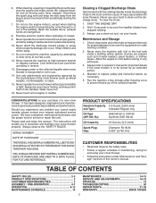
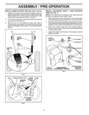
...HOW TO SET UP YOUR SNOW THROWER TOOL BOX (See Fig. 10) A toolbox is located on your snow thrower. Remove all parts and hardware you assemble must be tightened securely. Cut down all packing materials except plastic tie holding speed control rod to assemble or operate...(179829) (1) SPRING (184505) ASSEMBLY / PRE-OPERATION Read these instructions and this manual in its entirety before you attempt to lower handle. 5. All parts such as necessary to complete the assembly have been placed in the toolbox. 4 Reading the entire manual will assist you in assembly, operation and maintenance...
...HOW TO SET UP YOUR SNOW THROWER TOOL BOX (See Fig. 10) A toolbox is located on your snow thrower. Remove all parts and hardware you assemble must be tightened securely. Cut down all packing materials except plastic tie holding speed control rod to assemble or operate...(179829) (1) SPRING (184505) ASSEMBLY / PRE-OPERATION Read these instructions and this manual in its entirety before you attempt to lower handle. 5. All parts such as necessary to complete the assembly have been placed in the toolbox. 4 Reading the entire manual will assist you in assembly, operation and maintenance...
User Manual
Page 5
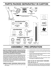
... securing rod to lower handle. With top end of rod positioned under left side of control panel, push rod down and insert top end of parts. Remove plastic tie securing rod to lower handle. 2. PLASTIC TIE TRACTION DRIVE CONTROL ROD VINYL SLEEVE HANDLE KNOB LOWER HANDLE Fig. 1 SPEED CONTROL ROD RETAINER...
... securing rod to lower handle. With top end of rod positioned under left side of control panel, push rod down and insert top end of parts. Remove plastic tie securing rod to lower handle. 2. PLASTIC TIE TRACTION DRIVE CONTROL ROD VINYL SLEEVE HANDLE KNOB LOWER HANDLE Fig. 1 SPEED CONTROL ROD RETAINER...
User Manual
Page 6
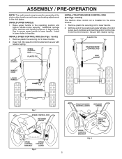
... DISCHARGE CHUTE / CHUTE ROTATOR HEAD (See Fig. 7) NOTE: The multi-wrench provided in rod end. 2. Install 3/8 washer and locknut on rod and insert end of parts and retrieve the auger control rod from bag of rod into control arm with discharge opening up as shown. (See Fig. 5) 3. Hook end of chute... top end of rod positioned under right side of control panel, push down on threaded stud and tighten securely. Hook spring in hole in your parts bag may be used to align square and pin on pin and threaded stud of snow thrower. 2. Retrieve vinyl sleeve and spring from carton chute...
... DISCHARGE CHUTE / CHUTE ROTATOR HEAD (See Fig. 7) NOTE: The multi-wrench provided in rod end. 2. Install 3/8 washer and locknut on rod and insert end of parts and retrieve the auger control rod from bag of rod into control arm with discharge opening up as shown. (See Fig. 5) 3. Hook end of chute... top end of rod positioned under right side of control panel, push down on threaded stud and tighten securely. Hook spring in hole in your parts bag may be used to align square and pin on pin and threaded stud of snow thrower. 2. Retrieve vinyl sleeve and spring from carton chute...
User Manual
Page 10
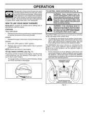
... by the position of the chute deflector. WARNING: If the discharge chute or auger become clogged, shut-off engine and wait for all moving parts to prevent unauthorized use. The DISTANCE that snow is thrown is controlled by the discharge chute control lever. • To change the discharge chute... to throw snow farther. • Press downward on the engine. TO CONTROL SNOW DISCHARGE (See Fig. 12) WARNING: Snow throwers have exposed rotating parts, which can result in foreign objects thrown into the eyes, which snow is in desired position. Use the clean-out tool, NOT YOUR HANDS, to...
... by the position of the chute deflector. WARNING: If the discharge chute or auger become clogged, shut-off engine and wait for all moving parts to prevent unauthorized use. The DISTANCE that snow is thrown is controlled by the discharge chute control lever. • To change the discharge chute... to throw snow farther. • Press downward on the engine. TO CONTROL SNOW DISCHARGE (See Fig. 12) WARNING: Snow throwers have exposed rotating parts, which can result in foreign objects thrown into the eyes, which snow is in desired position. Use the clean-out tool, NOT YOUR HANDS, to...
User Manual
Page 11
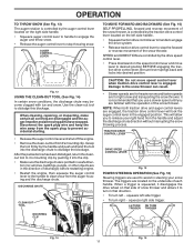
... and reverse movement of the snow thrower. The triggers are controlled by pushing it 's mounting clip. When cleaning, repairing, or inspecting, make certain all moving parts have stopped. TRACTION DRIVE CONTROL LEVER DRIVE SPEED CONTROL LEVER Fig. 15 POWER STEERING OPERATION (See Fig. 16) Steering triggers are used to stop the...
... and reverse movement of the snow thrower. The triggers are controlled by pushing it 's mounting clip. When cleaning, repairing, or inspecting, make certain all moving parts have stopped. TRACTION DRIVE CONTROL LEVER DRIVE SPEED CONTROL LEVER Fig. 15 POWER STEERING OPERATION (See Fig. 16) Steering triggers are used to stop the...
User Manual
Page 12
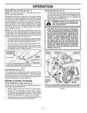
... and formation of the auger housing and adjust the clearance between the scraper bar and the ground. Check engine oil with snow thrower on your parts bag may be cleared is uneven. Purchase fuel in quantities that can be sure skid plates are located on dipstick is reached. To avoid engine... tank to assure fuel freshness. Acidic gas can attract moisture which can easily be picked up and thrown by loosening the hex nuts, then moving parts to adjust the skid plates. Never use it run until "FULL" mark on each side of acids during storage. FIG. 18 12 Skid plates are...
... and formation of the auger housing and adjust the clearance between the scraper bar and the ground. Check engine oil with snow thrower on your parts bag may be cleared is uneven. Purchase fuel in quantities that can be sure skid plates are located on dipstick is reached. To avoid engine... tank to assure fuel freshness. Acidic gas can attract moisture which can easily be picked up and thrown by loosening the hex nuts, then moving parts to adjust the skid plates. Never use it run until "FULL" mark on each side of acids during storage. FIG. 18 12 Skid plates are...
User Manual
Page 14
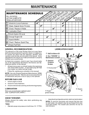
... engine run better and last longer. • Follow the maintenance schedule in this manual. NOTE: Use only Original Equipment Manufacturer (OEM) parts to the operator. LUBRICATION Keep your local parts dealer. At least once a season, check to slow leaks, tire sealant may be sure they are functioning properly. BEFORE EACH USE 1. Check...
... engine run better and last longer. • Follow the maintenance schedule in this manual. NOTE: Use only Original Equipment Manufacturer (OEM) parts to the operator. LUBRICATION Keep your local parts dealer. At least once a season, check to slow leaks, tire sealant may be sure they are functioning properly. BEFORE EACH USE 1. Check...
User Manual
Page 16
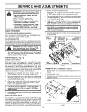
...and reconnect spark plug wire to stop . 2. Replace belt cover by installing cover and screws and tighten securely. Wait for all moving parts have completely stopped. 4. Install 1/4-20 locknuts and tighten securely. Use only original equipment shear bolts as supplied with your snow thrower.... bolts as supplied with your snow thrower. 4. Make sure the augers and all controls and move throttle control to spark plug. Disengage all moving parts to spark plug. 1/4-20 LOCKNUT 1/4-20 x 1-5/8 CAPSCREW / SHEAR BOLT IMPELLER HUB IMPELLER SHAFT 1/4-20 x 2 SHOULDER / SHEAR BOLT AUGER...
...and reconnect spark plug wire to stop . 2. Replace belt cover by installing cover and screws and tighten securely. Wait for all moving parts have completely stopped. 4. Install 1/4-20 locknuts and tighten securely. Use only original equipment shear bolts as supplied with your snow thrower.... bolts as supplied with your snow thrower. 4. Make sure the augers and all controls and move throttle control to spark plug. Disengage all moving parts to spark plug. 1/4-20 LOCKNUT 1/4-20 x 1-5/8 CAPSCREW / SHEAR BOLT IMPELLER HUB IMPELLER SHAFT 1/4-20 x 2 SHOULDER / SHEAR BOLT AUGER...
User Manual
Page 18
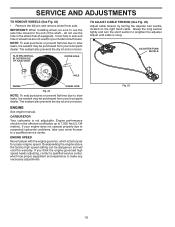
...your snow thrower to make any necessary adjustments. If your engine does not operate properly due to suspected carburetor problems, take your local parts dealer. ENGINE SPEED Never tamper with the engine governor, which has proper equipment and experience to a qualified service center. If you ...think the engine-governed high speed needs adjusting, contact a qualified service center, which is factory set for your local parts dealer. do not use the axle hole closest to the end of the shaft - SERVICE AND ADJUSTMENTS TO REMOVE WHEELS (See Fig. 22)...
...your snow thrower to make any necessary adjustments. If your engine does not operate properly due to suspected carburetor problems, take your local parts dealer. ENGINE SPEED Never tamper with the engine governor, which has proper equipment and experience to a qualified service center. If you ...think the engine-governed high speed needs adjusting, contact a qualified service center, which is factory set for your local parts dealer. do not use the axle hole closest to the end of the shaft - SERVICE AND ADJUSTMENTS TO REMOVE WHEELS (See Fig. 22)...
User Manual
Page 19
... which allows condensation to form and will not be stored for a period of time, clean it from forming in essential fuel system parts such as shown in the Service and Adjustments section of this manual). Plastic cannot breathe, which leads to separation and formation of acids... safe place. • Do not store gasoline from one ounce (29 ml) of this manual. 4. store it to distribute oil. 4. Inspect moving parts for damage, breakage and wear. ENGINE See engine manual. Rust and/or dirt in any enclosure. Allow the engine to cool before painting. Inspect and...
... which allows condensation to form and will not be stored for a period of time, clean it from forming in essential fuel system parts such as shown in the Service and Adjustments section of this manual). Plastic cannot breathe, which leads to separation and formation of acids... safe place. • Do not store gasoline from one ounce (29 ml) of this manual. 4. store it to distribute oil. 4. Inspect moving parts for damage, breakage and wear. ENGINE See engine manual. Rust and/or dirt in any enclosure. Allow the engine to cool before painting. Inspect and...
User Manual
Page 20
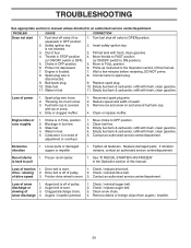
... a few minutes before restarting, DO NOT prime. 8. Throwing too much snow. 3. Reduce speed and width of traction 1. Replace damaged parts. If vibration remains, contact an authorized service center/department. Frozen recoil starter. 1. Loss of swath. 3. Friction drive wheel is not ...gasoline. 4. Empty fuel tank & carburetor, refill with fresh, clean gasoline. 4. Spark plug wire loose. 2. Clean or replace muffler. Loose parts or damaged augers or impeller. 1. Tighten all fasteners. Drive belt is flooded. 8. Augers / impeller jammed. 1. Remove debris or foreign object...
... a few minutes before restarting, DO NOT prime. 8. Throwing too much snow. 3. Reduce speed and width of traction 1. Replace damaged parts. If vibration remains, contact an authorized service center/department. Frozen recoil starter. 1. Loss of swath. 3. Friction drive wheel is not ...gasoline. 4. Empty fuel tank & carburetor, refill with fresh, clean gasoline. 4. Spark plug wire loose. 2. Clean or replace muffler. Loose parts or damaged augers or impeller. 1. Tighten all fasteners. Drive belt is flooded. 8. Augers / impeller jammed. 1. Remove debris or foreign object...
User Manual
Page 21
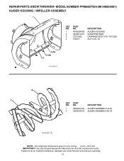
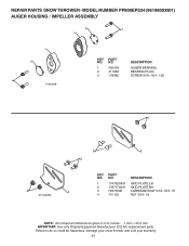
... IMPORTANT: Use only Original Equipment Manufacturer (O.E.M.) replacement parts. MODEL NUMBER PP800EPS24 (96198003901) AUGER HOUSING / IMPELLER ASSEMBLY 1 KEY NO. 1 2 3 4 PART NO. 404928X428 404931X431 72270505 155377 DESCRIPTION AUGER HOUSING SCRAPPER BAR CARRIAGE BOLT 5/16−18 X .625 NUT 5/16−18 3 (5x) 4 (5x) 2 01.07.001-A 2 1 KEY NO. 1 2 PART NO. 420493X479 420494X479 DESCRIPTION AUGER ASSEMBLY LH...
... IMPORTANT: Use only Original Equipment Manufacturer (O.E.M.) replacement parts. MODEL NUMBER PP800EPS24 (96198003901) AUGER HOUSING / IMPELLER ASSEMBLY 1 KEY NO. 1 2 3 4 PART NO. 404928X428 404931X431 72270505 155377 DESCRIPTION AUGER HOUSING SCRAPPER BAR CARRIAGE BOLT 5/16−18 X .625 NUT 5/16−18 3 (5x) 4 (5x) 2 01.07.001-A 2 1 KEY NO. 1 2 PART NO. 420493X479 420494X479 DESCRIPTION AUGER ASSEMBLY LH...
User Manual
Page 22
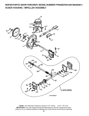
REPAIR PARTS SNOW THROWER - inches. 1 inch = 25.4 mm IMPORTANT: Use only Original Equipment Manufacturer (O.E.M.) replacement parts. MODEL NUMBER PP800EPS24 (96198003901) AUGER HOUSING / IMPELLER ASSEMBLY 5 15 14 4 11 6 11 16 12 13 11 3 12 10 11 7 8 17 1 9 37 2 9 9 33 37 32 34 30 31 31 29 28 26 27 36 20 21 22 23 25 35 24 23 22 21 18 19 2 (EXPLODED) 01.07.026-D NOTE: All component dimensions given in U.S. Failure to do so could be hazardous, damage your snow thrower and void your warranty. 22
REPAIR PARTS SNOW THROWER - inches. 1 inch = 25.4 mm IMPORTANT: Use only Original Equipment Manufacturer (O.E.M.) replacement parts. MODEL NUMBER PP800EPS24 (96198003901) AUGER HOUSING / IMPELLER ASSEMBLY 5 15 14 4 11 6 11 16 12 13 11 3 12 10 11 7 8 17 1 9 37 2 9 9 33 37 32 34 30 31 31 29 28 26 27 36 20 21 22 23 25 35 24 23 22 21 18 19 2 (EXPLODED) 01.07.026-D NOTE: All component dimensions given in U.S. Failure to do so could be hazardous, damage your snow thrower and void your warranty. 22
User Manual
Page 23
... could be hazardous, damage your snow thrower and void your warranty. 23 inches. 1 inch = 25.4 mm IMPORTANT: Use only Original Equipment Manufacturer (O.E.M.) replacement parts. REPAIR PARTS SNOW THROWER - MODEL NUMBER PP800EPS24 (96198003901) AUGER HOUSING / IMPELLER ASSEMBLY KEY NO. 1 2 3 4 5 6 7 8 9 10 11 12 13 14 15 16 17 18 19 20... 21 22 23 24 25 26 27 28 29 30 31 32 33 34 35 36 37 PART NO. 175321X431 427148 188909 427146 175322 178675X431 ...
... could be hazardous, damage your snow thrower and void your warranty. 23 inches. 1 inch = 25.4 mm IMPORTANT: Use only Original Equipment Manufacturer (O.E.M.) replacement parts. REPAIR PARTS SNOW THROWER - MODEL NUMBER PP800EPS24 (96198003901) AUGER HOUSING / IMPELLER ASSEMBLY KEY NO. 1 2 3 4 5 6 7 8 9 10 11 12 13 14 15 16 17 18 19 20... 21 22 23 24 25 26 27 28 29 30 31 32 33 34 35 36 37 PART NO. 175321X431 427148 188909 427146 175322 178675X431 ...
User Manual
Page 24
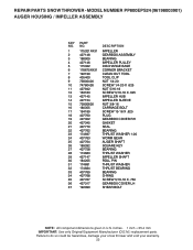
... PLATE RH 1 3 72270506 CARRIAGE BOLT 5/16−18 X .75 4 751153 NUT 5/16−18 NOTE: All component dimensions given in U.S. MODEL NUMBER PP800EPS24 (96198003901) AUGER HOUSING / IMPELLER ASSEMBLY 2 3 1 1 2 3 01.07.024-B KEY NO. 1 2 3 PART NO. 420478 411939 179582 DESCRIPTION AUGER BEARING BEARING PLUG SCREW 5/16−18 X 1.00 4 4 01.11.001-B 3 2 3 KEY...
... PLATE RH 1 3 72270506 CARRIAGE BOLT 5/16−18 X .75 4 751153 NUT 5/16−18 NOTE: All component dimensions given in U.S. MODEL NUMBER PP800EPS24 (96198003901) AUGER HOUSING / IMPELLER ASSEMBLY 2 3 1 1 2 3 01.07.024-B KEY NO. 1 2 3 PART NO. 420478 411939 179582 DESCRIPTION AUGER BEARING BEARING PLUG SCREW 5/16−18 X 1.00 4 4 01.11.001-B 3 2 3 KEY...
User Manual
Page 25
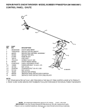
... your warranty. 25 ITEMS 15 AND 16 ARE SERVICE PART NUMBERS TO ALLOW PURCHASE OF INDIVIDUAL ITEMS IF NECESSARY. REPAIR PARTS SNOW THROWER - inches. 1 inch = 25.4 mm IMPORTANT: Use only Original Equipment Manufacturer (O.E.M.) replacement parts. MODEL NUMBER PP800EPS24 (96198003901) CONTROL PANEL / CHUTE 5 7 15 3... 16 *14 KEY NO. 1 2 3 4 5 6 7 8 9 *10 *11 *12 *13 *14 15 16 PART NO. 435023X428 178633X428 420673 420325 414280 128415 ...
... your warranty. 25 ITEMS 15 AND 16 ARE SERVICE PART NUMBERS TO ALLOW PURCHASE OF INDIVIDUAL ITEMS IF NECESSARY. REPAIR PARTS SNOW THROWER - inches. 1 inch = 25.4 mm IMPORTANT: Use only Original Equipment Manufacturer (O.E.M.) replacement parts. MODEL NUMBER PP800EPS24 (96198003901) CONTROL PANEL / CHUTE 5 7 15 3... 16 *14 KEY NO. 1 2 3 4 5 6 7 8 9 *10 *11 *12 *13 *14 15 16 PART NO. 435023X428 178633X428 420673 420325 414280 128415 ...
User Manual
Page 26
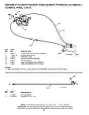
... THROWER - MODEL NUMBER PP800EPS24 (96198003901) CONTROL PANEL / CHUTE 2 2 *3 1 *7 *6 KEY NO. 1 2 *3 *4 *5 *6 *7 PART NO. 428272 17501010 420678 405932 420675 428273 428310 DESCRIPTION LEVER/CABLE ROTATOR ASSEMBLY SCREW 10-24 X .625 ROTATOR HEAD ROTATOR PIVOT ... void your warranty. 26 inches. 1 inch = 25.4 mm IMPORTANT: Use only Original Equipment Manufacturer (O.E.M.) replacement parts. ITEMS INDICATED WITH AN * ARE LISTED AS REFERENCE FOR SERVICE PARTS ONLY. 2 1 KEY NO. 1 2 PART NO. 421249 74041024 DESCRIPTION STEER CABLE SCREW 10−24 X 1.50 01.15.009-A NOTE: All component ...
... THROWER - MODEL NUMBER PP800EPS24 (96198003901) CONTROL PANEL / CHUTE 2 2 *3 1 *7 *6 KEY NO. 1 2 *3 *4 *5 *6 *7 PART NO. 428272 17501010 420678 405932 420675 428273 428310 DESCRIPTION LEVER/CABLE ROTATOR ASSEMBLY SCREW 10-24 X .625 ROTATOR HEAD ROTATOR PIVOT ... void your warranty. 26 inches. 1 inch = 25.4 mm IMPORTANT: Use only Original Equipment Manufacturer (O.E.M.) replacement parts. ITEMS INDICATED WITH AN * ARE LISTED AS REFERENCE FOR SERVICE PARTS ONLY. 2 1 KEY NO. 1 2 PART NO. 421249 74041024 DESCRIPTION STEER CABLE SCREW 10−24 X 1.50 01.15.009-A NOTE: All component ...
User Manual
Page 27
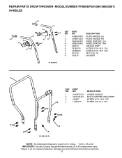
... THROWER - NO. MODEL NUMBER PP800EPS24 (96198003901) HANDLES 5 1 6 8 5 8 6 2 39 7 8 49 7 KEY PART NO. NO. DESCRIPTION 1 419800X431 PLOW HANDLE LH 2 419801X431 PLOW HANDLE RH 3 196944X431 PANEL BRACKET LH 4 196943X431 PANEL BRACKET RH ...GRIP 6 74780512 SCREW 5/16−18 X .750 7 74780524 SCREW 5/16−18 X 1.50 8 751153 NUT 5/16−18 9 155415 WASHER 01.08.003-A 1 KEY PART NO. DESCRIPTION 1 419797X431 LOWER HANDLE 2 427513X431 PIVOT SUPPORT WELDMENT 3 428867 SCREW 5/16−18 X .750 2 4 17000616 SCREW 3/8−16 X 1.00 4 3 4 3 4...
... THROWER - NO. MODEL NUMBER PP800EPS24 (96198003901) HANDLES 5 1 6 8 5 8 6 2 39 7 8 49 7 KEY PART NO. NO. DESCRIPTION 1 419800X431 PLOW HANDLE LH 2 419801X431 PLOW HANDLE RH 3 196944X431 PANEL BRACKET LH 4 196943X431 PANEL BRACKET RH ...GRIP 6 74780512 SCREW 5/16−18 X .750 7 74780524 SCREW 5/16−18 X 1.50 8 751153 NUT 5/16−18 9 155415 WASHER 01.08.003-A 1 KEY PART NO. DESCRIPTION 1 419797X431 LOWER HANDLE 2 427513X431 PIVOT SUPPORT WELDMENT 3 428867 SCREW 5/16−18 X .750 2 4 17000616 SCREW 3/8−16 X 1.00 4 3 4 3 4...


