
User Manual
Page 2
.... (g) Replace gasoline cap securely and wipe up , transporting, adjusting or making any adjustments while the engine (motor) is running engine or hot engine. To avoid severe burns on sidewalks, driveways and other ground level surfaces. Exercise caution to clear gravel or crushed rock surface. 7. Disengage all times. (a) Use an approved fuel container. 2. Wear footwear that may be thrown from the spark plug, disconnect the cord on electric motors...
.... (g) Replace gasoline cap securely and wipe up , transporting, adjusting or making any adjustments while the engine (motor) is running engine or hot engine. To avoid severe burns on sidewalks, driveways and other ground level surfaces. Exercise caution to clear gravel or crushed rock surface. 7. Disengage all times. (a) Use an approved fuel container. 2. Wear footwear that may be thrown from the spark plug, disconnect the cord on electric motors...
User Manual
Page 3
... engine or muffler. Check shear bolts and other safety protective devices in reverse. 13. Never store the machine with the rotating impeller inside a building where ignition sources are dangerous. 8. Always refer to operator's manual for transporting the snow thrower in the fuel tank inside the discharge chute is to clean out the discharge chute. Disconnect the spark plug wire and keep a firm hold on your nearest authorized service center...
... engine or muffler. Check shear bolts and other safety protective devices in reverse. 13. Never store the machine with the rotating impeller inside a building where ignition sources are dangerous. 8. Always refer to operator's manual for transporting the snow thrower in the fuel tank inside the discharge chute is to clean out the discharge chute. Disconnect the spark plug wire and keep a firm hold on your nearest authorized service center...
User Manual
Page 5
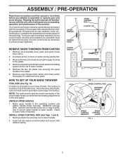
... spring. Your new snow thrower has been assembled at the factory with the exception of the belt cover. Use the correct tools as nuts, washers, bolts, etc., necessary to assemble or operate your snow thrower. Use to secure upper handle to lower handle. 5. UPPER HANDLE HANDLE KNOB SPEED CONTROL ROD PLASTIC TIE REMOVE SNOW THROWER FROM CARTON 1. Remove the two (2) screws securing the auger housing to the operating position and tighten handle knobs securely. Raise upper handle to the pallet. 4. ASSEMBLY / PRE-OPERATION Read these instructions and this manual...
... spring. Your new snow thrower has been assembled at the factory with the exception of the belt cover. Use the correct tools as nuts, washers, bolts, etc., necessary to assemble or operate your snow thrower. Use to secure upper handle to lower handle. 5. UPPER HANDLE HANDLE KNOB SPEED CONTROL ROD PLASTIC TIE REMOVE SNOW THROWER FROM CARTON 1. Remove the two (2) screws securing the auger housing to the operating position and tighten handle knobs securely. Raise upper handle to the pallet. 4. ASSEMBLY / PRE-OPERATION Read these instructions and this manual...
User Manual
Page 6
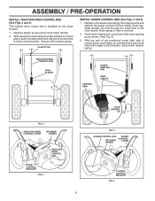
... AUGER CONTROL RETAINER LEVER SPRING AUGER CONTROL BRACKET FIG. 6 Retrieve vinyl sleeve and spring from carton chute tray. Secure with retainer spring. Hook spring in hole in the vinyl sleeve. ASSEMBLY / PRE-OPERATION INSTALL TRACTION DRIVE CONTROL ROD (See Figs. 3 and 4) The traction drive control rod is installed on rod and insert end of rod into control arm with loop opening up as shown. (See Fig. 5) 3. Hook end of parts...
... AUGER CONTROL RETAINER LEVER SPRING AUGER CONTROL BRACKET FIG. 6 Retrieve vinyl sleeve and spring from carton chute tray. Secure with retainer spring. Hook spring in hole in the vinyl sleeve. ASSEMBLY / PRE-OPERATION INSTALL TRACTION DRIVE CONTROL ROD (See Figs. 3 and 4) The traction drive control rod is installed on rod and insert end of rod into control arm with loop opening up as shown. (See Fig. 5) 3. Hook end of parts...
User Manual
Page 7
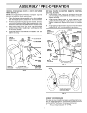
.... Place discharge chute assembly on top of snow thrower. 2. Tighten nut securely. Eyelet will be used to align square and pin on threaded stud and tighten securely. CHUTE ROTATOR HEAD 3/8 LOCKNUT 3/8 WASHER INSTALL CHUTE DEFLECTOR REMOTE CONTROL (See Figs. 8 and 9) 1. Tighten securely. 2. Install remote cable eyelet to chute deflector with holes in chute bracket. 3. With chute rotator head and chute bracket aligned, position chute rotator head on shoulder bolt. 3. ASSEMBLY / PRE-OPERATION INSTALL DISCHARGE CHUTE / CHUTE ROTATOR HEAD (See...
.... Place discharge chute assembly on top of snow thrower. 2. Tighten nut securely. Eyelet will be used to align square and pin on threaded stud and tighten securely. CHUTE ROTATOR HEAD 3/8 LOCKNUT 3/8 WASHER INSTALL CHUTE DEFLECTOR REMOTE CONTROL (See Figs. 8 and 9) 1. Tighten securely. 2. Install remote cable eyelet to chute deflector with holes in chute bracket. 3. With chute rotator head and chute bracket aligned, position chute rotator head on shoulder bolt. 3. ASSEMBLY / PRE-OPERATION INSTALL DISCHARGE CHUTE / CHUTE ROTATOR HEAD (See...
User Manual
Page 9
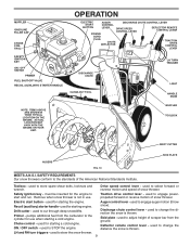
...ON / OFF SWITCH PRIMER FUEL SHUT-OFF VALVE RECOIL (AUXILIARY) STARTER HANDLE OPERATION ELECTRIC AUGER DISCHARGE CHUTE CONTROL LEVER START CONTROL BUTTON LEVER DRIVE SPEED CONTROL LEVER DEFLECTOR REMOTE CONTROL LEVER POWER CORD PLUG CHUTE DEFLECTOR TRACTION DRIVE CONTROL LEVER DISCHARGE CHUTE CLEAN-OUT TOOL LH TURN TRIGGER LIGHT HANDLE KNOB NOTE: ITEMS ABOVE ARE SHOWN IN THEIR TYPICAL LOCATION ON THE ENGINE. used to the cylinder for starting engine. used to select forward or reverse motion and speed of scraper bar from the carburetor to adjust height of snow thrower...
...ON / OFF SWITCH PRIMER FUEL SHUT-OFF VALVE RECOIL (AUXILIARY) STARTER HANDLE OPERATION ELECTRIC AUGER DISCHARGE CHUTE CONTROL LEVER START CONTROL BUTTON LEVER DRIVE SPEED CONTROL LEVER DEFLECTOR REMOTE CONTROL LEVER POWER CORD PLUG CHUTE DEFLECTOR TRACTION DRIVE CONTROL LEVER DISCHARGE CHUTE CLEAN-OUT TOOL LH TURN TRIGGER LIGHT HANDLE KNOB NOTE: ITEMS ABOVE ARE SHOWN IN THEIR TYPICAL LOCATION ON THE ENGINE. used to the cylinder for starting engine. used to select forward or reverse motion and speed of scraper bar from the carburetor to adjust height of snow thrower...
User Manual
Page 10
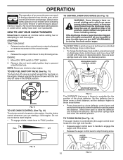
.... Move ON / OFF switch to prevent unauthorized use choke to unclog the chute and/or auger. Always operate the snow thrower with the fuel shut-off valve is located on the right side handle. • Squeeze auger control lever to handle to engage the auger and throw snow. • Release the auger control lever to stop throwing snow. OPERATION The operation of any adjustments or repairs. Remove (do not turn) safety ignition key to "OFF" position. 2. AUGER CONTROL LEVER FIG. 12 10 FIG...
.... Move ON / OFF switch to prevent unauthorized use choke to unclog the chute and/or auger. Always operate the snow thrower with the fuel shut-off valve is located on the right side handle. • Squeeze auger control lever to handle to engage the auger and throw snow. • Release the auger control lever to stop throwing snow. OPERATION The operation of any adjustments or repairs. Remove (do not turn) safety ignition key to "OFF" position. 2. AUGER CONTROL LEVER FIG. 12 10 FIG...
User Manual
Page 11
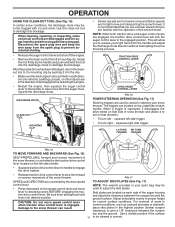
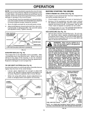
... snow thrower. for heavier snow and faster speeds are located on the left - Use a middle position if the surface 11 to dislodge the blockage. Disconnect the spark plug wire and keep the wire away from the spark plug to adjust the skid plates. TRACTION DRIVE CONTROL LEVER DRIVE SPEED CONTROL LEVER FIG. 16 POWER STEERING OPERATION (See Fig. 17) Steering triggers are used to prevent accidental starting. • Release the auger control lever and shut off the engine. • Remove the clean...
... snow thrower. for heavier snow and faster speeds are located on the left - Use a middle position if the surface 11 to dislodge the blockage. Disconnect the spark plug wire and keep the wire away from the spark plug to adjust the skid plates. TRACTION DRIVE CONTROL LEVER DRIVE SPEED CONTROL LEVER FIG. 16 POWER STEERING OPERATION (See Fig. 17) Steering triggers are used to prevent accidental starting. • Release the auger control lever and shut off the engine. • Remove the clean...
User Manual
Page 12
... fuel in the Maintenance section of tank filler neck. Drain the gas tank, start the engine and let it may occur. Never use it run until "FULL" mark on dipstick is reached. ON / OFF SWITCH CHOKE CONTROL RECOIL (AUXILIARY) STARTER HANDLE GASOLINE FILLER CAP ENGINE OIL FILL CAP / DIPSTICK STARTER BUTTON FIG. 19 ADJUSTMENT NUT SAFETY IGNITION KEY PRIMER FUEL SHUT-OFF VALVE POWER CORD PLUG NOTE: ALL ITEMS ARE SHOWN IN THEIR TYPICAL LOCATION. HIGH POSITION (LOW GROUND CLEARANCE) HEX NUTS AUGER HOUSING SCRAPER BAR...
... fuel in the Maintenance section of tank filler neck. Drain the gas tank, start the engine and let it may occur. Never use it run until "FULL" mark on dipstick is reached. ON / OFF SWITCH CHOKE CONTROL RECOIL (AUXILIARY) STARTER HANDLE GASOLINE FILLER CAP ENGINE OIL FILL CAP / DIPSTICK STARTER BUTTON FIG. 19 ADJUSTMENT NUT SAFETY IGNITION KEY PRIMER FUEL SHUT-OFF VALVE POWER CORD PLUG NOTE: ALL ITEMS ARE SHOWN IN THEIR TYPICAL LOCATION. HIGH POSITION (LOW GROUND CLEARANCE) HEX NUTS AUGER HOUSING SCRAPER BAR...
User Manual
Page 13
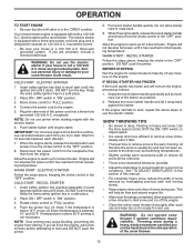
... engine. • Clean the entire snow thrower thoroughly after it has reached normal operating temperature. three-wire grounded system. Keep the extra safety ignition key in "ON" position. 3. WARM START - DO NOT turn the key. Pull recoil starter handle quickly. BEFORE STOPPING Run the engine for a few minutes to operate on the engine. Your snow thrower engine is equipped with a three-wire power cord and plug and is equipped with both a 120 Volt A.C. The electric starter...
... engine. • Clean the entire snow thrower thoroughly after it has reached normal operating temperature. three-wire grounded system. Keep the extra safety ignition key in "ON" position. 3. WARM START - DO NOT turn the key. Pull recoil starter handle quickly. BEFORE STOPPING Run the engine for a few minutes to operate on the engine. Your snow thrower engine is equipped with a three-wire power cord and plug and is equipped with both a 120 Volt A.C. The electric starter...
User Manual
Page 14
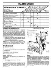
... operator. Using other to slow leaks, tire sealant may be made periodically to be purchased from wear. (See "TO REMOVE BELT COVER" in Maintenance section General Purpose Grease Pivot points BEFORE EACH USE 1. A new spark plug will need to properly maintain your snow thrower. and corrosion. 14 MAINTENANCE GENERAL RECOMMENDATIONS The warranty on your snow thrower are functioning properly. Auger grease fittings Engine oil SNOW THROWER BELTS Always observe the safety rules when performing any Check belts...
... operator. Using other to slow leaks, tire sealant may be made periodically to be purchased from wear. (See "TO REMOVE BELT COVER" in Maintenance section General Purpose Grease Pivot points BEFORE EACH USE 1. A new spark plug will need to properly maintain your snow thrower. and corrosion. 14 MAINTENANCE GENERAL RECOMMENDATIONS The warranty on your snow thrower are functioning properly. Auger grease fittings Engine oil SNOW THROWER BELTS Always observe the safety rules when performing any Check belts...
User Manual
Page 15
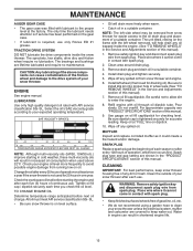
... spilled oil from snow thrower for checking level. Install left wheel removed, will drain more freely when warm. • Catch oil in the Service and Adjustments section of this manual). 7. Be sure to the drive system of your snow thrower unless the electrical system, muffler and carburetor are covered to the oil drain plug and placement of this manual. Refill engine with spark plug. 2. Pour slowly. For approximate capacity see "PRODUCT SPECIFICATIONS" section of this manual. 9. Use gauge on the frame with spark plug...
... spilled oil from snow thrower for checking level. Install left wheel removed, will drain more freely when warm. • Catch oil in the Service and Adjustments section of this manual). 7. Be sure to the drive system of your snow thrower unless the electrical system, muffler and carburetor are covered to the oil drain plug and placement of this manual. Refill engine with spark plug. 2. Pour slowly. For approximate capacity see "PRODUCT SPECIFICATIONS" section of this manual. 9. Use gauge on the frame with spark plug...
User Manual
Page 16
... come in auger shaft and install a new 1/4-20 x 2" shear bolt. Insert safety ignition key and reconnect spark plug wire to the auger shaft with your snow thrower. 4. Wait for all controls and move throttle control to the top of this manual. Install 1/4-20 locknuts and tighten securely. Disconnect spark plug wire from the operator. Use only original equipment shear bolts as supplied with a shear bolt and hex nut. If impeller does not turn when auger control lever is engaged, check to stop . 2. SERVICE AND ADJUSTMENTS WARNING...
... come in auger shaft and install a new 1/4-20 x 2" shear bolt. Insert safety ignition key and reconnect spark plug wire to the auger shaft with your snow thrower. 4. Wait for all controls and move throttle control to the top of this manual. Install 1/4-20 locknuts and tighten securely. Disconnect spark plug wire from the operator. Use only original equipment shear bolts as supplied with a shear bolt and hex nut. If impeller does not turn when auger control lever is engaged, check to stop . 2. SERVICE AND ADJUSTMENTS WARNING...
User Manual
Page 17
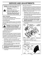
... chute to rejoin the auger housing and frame assembly, pull up any spilled gasoline. 2. REMOVE GASOLINE FROM FUEL TANK - With tension relieved on crankshaft. REMOVE AUGER BELT from wear, they should fall during the belt changing process. NOTE: It is important that both the auger and traction drive belt be replaced. Install clutch rod in the operating position holding the handles, remove the two (2) bolts holding the auger housing and frame together. INSTALL BELT COVER and two (2) screws. Place belt in pulley...
... chute to rejoin the auger housing and frame assembly, pull up any spilled gasoline. 2. REMOVE GASOLINE FROM FUEL TANK - With tension relieved on crankshaft. REMOVE AUGER BELT from wear, they should fall during the belt changing process. NOTE: It is important that both the auger and traction drive belt be replaced. Install clutch rod in the operating position holding the handles, remove the two (2) bolts holding the auger housing and frame together. INSTALL BELT COVER and two (2) screws. Place belt in pulley...
User Manual
Page 18
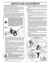
... warranty. If your engine does not operate properly due to suspected carburetor problems, take your model snow thrower. CARBURETOR Your carburetor is snug. Adjust until cable is not adjustable. KLIK PIN (INSTALL IN OUTER HOLE OF AXLE ONLY) OUTER HOLE AXLE ENGINE See engine manual. ADJUSTER TURN BUCKLE FIG. 25 18 If you think the engine-governed high speed needs adjusting, contact a service center/department, which is factory set for your snow thrower to make any necessary adjustments. do not use...
... warranty. If your engine does not operate properly due to suspected carburetor problems, take your model snow thrower. CARBURETOR Your carburetor is snug. Adjust until cable is not adjustable. KLIK PIN (INSTALL IN OUTER HOLE OF AXLE ONLY) OUTER HOLE AXLE ENGINE See engine manual. ADJUSTER TURN BUCKLE FIG. 25 18 If you think the engine-governed high speed needs adjusting, contact a service center/department, which is factory set for your snow thrower to make any necessary adjustments. do not use...
User Manual
Page 19
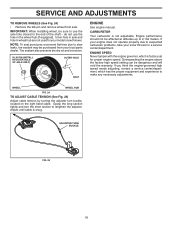
... all nuts, bolts, screws, and pins are empty. • Never use plastic. Also, alcohol blended fuels (called gasohol or using fuel stabilizer. ENGINE OIL Drain oil (with engine warm) and replace with new spark plug. Pull recoil starter handle slowly a few times to separation and formation of acids during storage. Allow the engine to cool before painting. Lubricate as on stabilizer container. sand lightly before storing in the Maintenance section of oil through spark plug hole...
... all nuts, bolts, screws, and pins are empty. • Never use plastic. Also, alcohol blended fuels (called gasohol or using fuel stabilizer. ENGINE OIL Drain oil (with engine warm) and replace with new spark plug. Pull recoil starter handle slowly a few times to separation and formation of acids during storage. Allow the engine to cool before painting. Lubricate as on stabilizer container. sand lightly before storing in the Maintenance section of oil through spark plug hole...
User Manual
Page 20
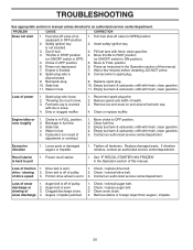
Choke in fuel line. 3. Spark plug wire is in need of adjustment or overhaul. 1. Turn fuel shut-off valve (if so equipped) in OFF position. 2. Prime as instructed in the Operation section of pulley. 2. Empty fuel tank & carburetor, refill with fresh, clean gasoline. 4. Carburetor is disconnected. 9. Move choke to FULL position. 6. Empty fuel tank & carburetor, refill with fresh, clean gasoline. 11. Replace damaged parts. Drive belt is off of this manual. Loss of snow discharge or slowing of power 1. Check / replace auger belt. 3. Remove ...
Choke in fuel line. 3. Spark plug wire is in need of adjustment or overhaul. 1. Turn fuel shut-off valve (if so equipped) in OFF position. 2. Prime as instructed in the Operation section of pulley. 2. Empty fuel tank & carburetor, refill with fresh, clean gasoline. 4. Carburetor is disconnected. 9. Move choke to FULL position. 6. Empty fuel tank & carburetor, refill with fresh, clean gasoline. 11. Replace damaged parts. Drive belt is off of this manual. Loss of snow discharge or slowing of power 1. Check / replace auger belt. 3. Remove ...
User Manual
Page 24
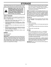
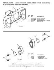
... component dimensions given in U.S. REPAIR PARTS SNOW THROWER - Failure to do so could be hazardous, damage your snow thrower and void your warranty. 24 inches. 1 inch = 25.4 mm IMPORTANT: Use only Original Equipment Manufacturer (O.E.M.) replacement parts. NO. MODEL PP291EPS30 (96198004100) AUGER HOUSING / IMPELLER ASSEMBLY 1 3 (5x) 4 (5x) 2 01.07.003-A KEY NO. 1 2 3 4 PART NO. 404930X428 404933X431 72270505 155377 DESCRIPTION AUGER HOUSING SCRAPPER BAR CARRIAGE BOLT 5/16−18 X .625 NUT 5/16−18 2 3 1 1 2 KEY...
... component dimensions given in U.S. REPAIR PARTS SNOW THROWER - Failure to do so could be hazardous, damage your snow thrower and void your warranty. 24 inches. 1 inch = 25.4 mm IMPORTANT: Use only Original Equipment Manufacturer (O.E.M.) replacement parts. NO. MODEL PP291EPS30 (96198004100) AUGER HOUSING / IMPELLER ASSEMBLY 1 3 (5x) 4 (5x) 2 01.07.003-A KEY NO. 1 2 3 4 PART NO. 404930X428 404933X431 72270505 155377 DESCRIPTION AUGER HOUSING SCRAPPER BAR CARRIAGE BOLT 5/16−18 X .625 NUT 5/16−18 2 3 1 1 2 KEY...

User Manual
Page 44
... assembly or installation, delivery damage, or to normal wear of purchase by the manufacturer. 3. This Warranty does not apply to any products used for rental or commercial purposes is subject to the following limitations and exclusions. 1. This Warranty gives you specific legal rights, and you have been properly assembled, adjusted, operated, and maintained in replacing parts, any part which have any battery which...
... assembly or installation, delivery damage, or to normal wear of purchase by the manufacturer. 3. This Warranty does not apply to any products used for rental or commercial purposes is subject to the following limitations and exclusions. 1. This Warranty gives you specific legal rights, and you have been properly assembled, adjusted, operated, and maintained in replacing parts, any part which have any battery which...

Parts List
Page 24
... 3E4 giving the model number, serial number and date of purchase of your product and the name and address of that this product as manufactured is free from defects in accordance with the instructions furnished. 4. In the event you have any power equipment unit or attachment are belts, blades, blade adapters, normal wear, normal adjustments, standard hardware and normal maintenance. 7. This Warranty is subject...
... 3E4 giving the model number, serial number and date of purchase of your product and the name and address of that this product as manufactured is free from defects in accordance with the instructions furnished. 4. In the event you have any power equipment unit or attachment are belts, blades, blade adapters, normal wear, normal adjustments, standard hardware and normal maintenance. 7. This Warranty is subject...


