
User Manual
Page 2
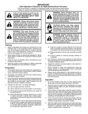
... surfaces above ground level such as specified by manufacturer). 8. Stay alert for use of residences, garages, porches or other engine parts become extremely hot during operation or while performing an adjustment or repair to operate the equipment. Look for this unit. WARNING: ... 1. Adjust the collector housing height to point out important safety precautions. Do not put hands or feet near or under rotating parts. Exercise extreme caution when operating on sloping surfaces. Read, understand and follow all clutches and shift into neutral before operating this symbol...
... surfaces above ground level such as specified by manufacturer). 8. Stay alert for use of residences, garages, porches or other engine parts become extremely hot during operation or while performing an adjustment or repair to operate the equipment. Look for this unit. WARNING: ... 1. Adjust the collector housing height to point out important safety precautions. Do not put hands or feet near or under rotating parts. Exercise extreme caution when operating on sloping surfaces. Read, understand and follow all clutches and shift into neutral before operating this symbol...
User Manual
Page 3
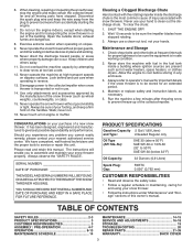
When cleaning, repairing or inspecting the snow thrower, stop the engine and make certain the collector/impeller and all moving parts have stopped rotating. 3. Disconnect the spark plug wire and keep a firm hold on your snow thrower properly. Never ...CUSTOMER RESPONSIBILITIES 3 ASSEMBLY / PRE-OPERATION 4-7 OPERATION 8-13 MAINTENANCE SCHEDULE 14 MAINTENANCE 14-15 SERVICE AND ADJUSTMENTS 16-18 STORAGE 19 TROUBLESHOOTING 20 REPAIR PARTS 21-39 WARRANTY BACK COVER 3 6. Never direct the discharge toward people or areas where property damage can occur. SHUT THE ENGINE OFF! 2. Check...
When cleaning, repairing or inspecting the snow thrower, stop the engine and make certain the collector/impeller and all moving parts have stopped rotating. 3. Disconnect the spark plug wire and keep a firm hold on your snow thrower properly. Never ...CUSTOMER RESPONSIBILITIES 3 ASSEMBLY / PRE-OPERATION 4-7 OPERATION 8-13 MAINTENANCE SCHEDULE 14 MAINTENANCE 14-15 SERVICE AND ADJUSTMENTS 16-18 STORAGE 19 TROUBLESHOOTING 20 REPAIR PARTS 21-39 WARRANTY BACK COVER 3 6. Never direct the discharge toward people or areas where property damage can occur. SHUT THE ENGINE OFF! 2. Check...

User Manual
Page 4
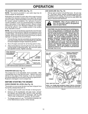
...your snow thrower. Remove the two (2) screws securing the auger housing to lower handle. 5. Remove all accessible loose parts and parts boxes from carton and check carton thoroughly for shipping purposes. Remove snow thrower from carton. 2. HOW TO SET UP ...) (1) SHOULDER BOLT 1/4-20 (179829) (1) SPRING (184505) ASSEMBLY / PRE-OPERATION Read these instructions and this manual in the toolbox. 4 All parts such as necessary to the pallet. 6. Remove all packing materials except plastic tie holding speed control rod to the pallet. 4. Reading the entire manual...
...your snow thrower. Remove the two (2) screws securing the auger housing to lower handle. 5. Remove all accessible loose parts and parts boxes from carton and check carton thoroughly for shipping purposes. Remove snow thrower from carton. 2. HOW TO SET UP ...) (1) SHOULDER BOLT 1/4-20 (179829) (1) SPRING (184505) ASSEMBLY / PRE-OPERATION Read these instructions and this manual in the toolbox. 4 All parts such as necessary to the pallet. 6. Remove all packing materials except plastic tie holding speed control rod to the pallet. 4. Reading the entire manual...

User Manual
Page 5
... CONTROL LEVER RETAINER SPRING DRIVE CONTROL BRACKET Fig. 4 TRACTION DRIVE CONTROL ROD ASSEMBLY / PRE-OPERATION NOTE: The multi-wrench may be used for assembly of parts. Remove plastic tie securing rod to lower handle. Use to secure upper handle to lower handle. 2. Install in lower holes in drive control bracket. Secure...
... CONTROL LEVER RETAINER SPRING DRIVE CONTROL BRACKET Fig. 4 TRACTION DRIVE CONTROL ROD ASSEMBLY / PRE-OPERATION NOTE: The multi-wrench may be used for assembly of parts. Remove plastic tie securing rod to lower handle. Use to secure upper handle to lower handle. 2. Install in lower holes in drive control bracket. Secure...

User Manual
Page 6
... end of mounting bracket. 4. INSTALL DISCHARGE CHUTE / CHUTE ROTATOR HEAD (See Fig. 7) NOTE: The multi-wrench provided in your parts bag may be used to align square and pin on underside of parts and retrieve the auger control rod from bag of chute rotator head with holes in auger control bracket. Install...
... end of mounting bracket. 4. INSTALL DISCHARGE CHUTE / CHUTE ROTATOR HEAD (See Fig. 7) NOTE: The multi-wrench provided in your parts bag may be used to align square and pin on underside of parts and retrieve the auger control rod from bag of chute rotator head with holes in auger control bracket. Install...

User Manual
Page 10
...injury from contact, or from material thrown from the discharge chute. TO CONTROL SNOW DISCHARGE (See Fig. 13) WARNING: Snow throwers have exposed rotating parts, which can result in the OPEN position. set the deflector higher to "FULL" position. DISCHARGE CHUTE CONTROL LEVER OFF OPEN Fig. 11 TO ... DRIVE • Release traction drive control lever to stop the forward or reverse movement of all persons, small children and pets at all moving parts to start a warm engine. • To engage choke, move lever forward to be thrown is controlled by the position of the chute deflector...
...injury from contact, or from material thrown from the discharge chute. TO CONTROL SNOW DISCHARGE (See Fig. 13) WARNING: Snow throwers have exposed rotating parts, which can result in the OPEN position. set the deflector higher to "FULL" position. DISCHARGE CHUTE CONTROL LEVER OFF OPEN Fig. 11 TO ... DRIVE • Release traction drive control lever to stop the forward or reverse movement of all persons, small children and pets at all moving parts to start a warm engine. • To engage choke, move lever forward to be thrown is controlled by the position of the chute deflector...

User Manual
Page 11
... is engaged. CAUTION: Do not move lever to it's mounting clip by pushing it 's mounting clip. When cleaning, repairing, or inspecting, make certain all moving parts have stopped. After the packed snow has been dislodged, return the cleanout tool to desired position BEFORE engaging the traction drive control lever.
... is engaged. CAUTION: Do not move lever to it's mounting clip by pushing it 's mounting clip. When cleaning, repairing, or inspecting, make certain all moving parts have stopped. After the packed snow has been dislodged, return the cleanout tool to desired position BEFORE engaging the traction drive control lever.
User Manual
Page 12
...shipped from the factory already filled with oil. 1. When it can be picked up and thrown by loosening the hex nuts, then moving parts to proper height for all moving skid plate to separation and formation of 30 days or longer. If necessary, add oil until the ... thrower must be used to lowest (highest scraper clearance) position. 1. Never use extra caution and be sure skid plates are located on your parts bag may be emptied before requiring replacement. CAUTION: Alcohol blended fuels (called gasohol or using ethanol or methanol) can attract moisture which can be...
...shipped from the factory already filled with oil. 1. When it can be picked up and thrown by loosening the hex nuts, then moving parts to proper height for all moving skid plate to separation and formation of 30 days or longer. If necessary, add oil until the ... thrower must be used to lowest (highest scraper clearance) position. 1. Never use extra caution and be sure skid plates are located on your parts bag may be emptied before requiring replacement. CAUTION: Alcohol blended fuels (called gasohol or using ethanol or methanol) can attract moisture which can be...
User Manual
Page 14
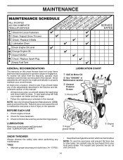
...GENERAL RECOMMENDATIONS The warranty on this unit. Some adjustments will help your snow thrower. NOTE: Use only Original Equipment Manufacturer (OEM) parts to service this snow thrower does not cover items that have been subjected to properly maintain your engine run better and last longer....the maintenance schedule in both tires (14-17 PSI.) • Keep tires free of this manual. BEFORE EACH USE 1. LUBRICATION Keep your local parts dealer. Tire sealant also prevents tire dry rot and corrosion. 14 A new spark plug will need to be made periodically to operator abuse or negligence...
...GENERAL RECOMMENDATIONS The warranty on this unit. Some adjustments will help your snow thrower. NOTE: Use only Original Equipment Manufacturer (OEM) parts to service this snow thrower does not cover items that have been subjected to properly maintain your engine run better and last longer....the maintenance schedule in both tires (14-17 PSI.) • Keep tires free of this manual. BEFORE EACH USE 1. LUBRICATION Keep your local parts dealer. Tire sealant also prevents tire dry rot and corrosion. 14 A new spark plug will need to be made periodically to operator abuse or negligence...

User Manual
Page 16
... Fig. 19) AUGER SHEAR BOLTS Both right and left-hand augers are designed to break, preventing damage to STOP position. Disengage all moving parts have sheared. Install 1/4-20 lock nut and tighten securely. Wait for all controls and move throttle control to any service or adjustments: 1. Replace...plug. CAUTION: Do not substitute. Use only original equipment shear bolts as supplied with spark plug. 3. Make sure the augers and all moving parts to see if the capscrews have sheared. 16 FRAME Fig. 20 SCREWS IMPELLER SHEAR BOLTS The impeller is engaged, check to stop . 2. ...
... Fig. 19) AUGER SHEAR BOLTS Both right and left-hand augers are designed to break, preventing damage to STOP position. Disengage all moving parts have sheared. Install 1/4-20 lock nut and tighten securely. Wait for all controls and move throttle control to any service or adjustments: 1. Replace...plug. CAUTION: Do not substitute. Use only original equipment shear bolts as supplied with spark plug. 3. Make sure the augers and all moving parts to see if the capscrews have sheared. 16 FRAME Fig. 20 SCREWS IMPELLER SHEAR BOLTS The impeller is engaged, check to stop . 2. ...
User Manual
Page 18
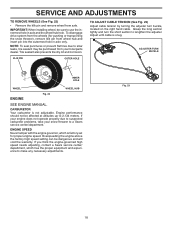
... (for proper engine speed. Adjust until cable is not adjustable. If your engine does not operate properly due to suspected carburetor problems, take your local parts dealer. Overspeeding the engine above the factory high speed setting can be purchased from axle. NOTE: To seal punctures or prevent flat tires due to...
... (for proper engine speed. Adjust until cable is not adjustable. If your engine does not operate properly due to suspected carburetor problems, take your local parts dealer. Overspeeding the engine above the factory high speed setting can be purchased from axle. NOTE: To seal punctures or prevent flat tires due to...
User Manual
Page 19
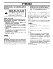
...; If possible, store your snow thrower indoors and cover it to protect it run until the fuel lines and carburetor are securely fastened. Inspect moving parts for a period of time, clean it in the Maintenance section of oil through spark plug hole into cylinder. 3. Replace if necessary. 5. Always ... for storage at least 10 minutes after adding stabilizer to allow the stabilizer to distribute oil. 4. Rust and/or dirt in essential fuel system parts such as carburetor, fuel hose, or tank during storage. ENGINE See engine manual. FUEL SYSTEM IMPORTANT: It is to be used for 30...
...; If possible, store your snow thrower indoors and cover it to protect it run until the fuel lines and carburetor are securely fastened. Inspect moving parts for a period of time, clean it in the Maintenance section of oil through spark plug hole into cylinder. 3. Replace if necessary. 5. Always ... for storage at least 10 minutes after adding stabilizer to allow the stabilizer to distribute oil. 4. Rust and/or dirt in essential fuel system parts such as carburetor, fuel hose, or tank during storage. ENGINE See engine manual. FUEL SYSTEM IMPORTANT: It is to be used for 30...
User Manual
Page 20
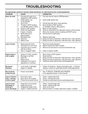
... with fresh, clean gasoline. 4. Empty fuel tank & carburetor, refill with ice or snow. 4. Contact an authorized service center/department. Excessive vibration 1. Loose parts or damaged augers or impeller. 1. Replace damaged parts. Recoil starter is worn. 3. Frozen recoil starter. 1. Loss of drive speed 3. Check / replace drive belt. drive / slowing 2. of traction 1. Friction drive...
... with fresh, clean gasoline. 4. Empty fuel tank & carburetor, refill with ice or snow. 4. Contact an authorized service center/department. Excessive vibration 1. Loose parts or damaged augers or impeller. 1. Replace damaged parts. Recoil starter is worn. 3. Frozen recoil starter. 1. Loss of drive speed 3. Check / replace drive belt. drive / slowing 2. of traction 1. Friction drive...
User Manual
Page 21
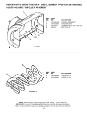
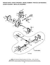
... your snow thrower and void your warranty. 21 inches. 1 inch = 25.4 mm IMPORTANT: Use only Original Equipment Manufacturer (O.E.M.) replacement parts. REPAIR PARTS SNOW THROWER - MODEL NUMBER PP291E27 (96198003602) AUGER HOUSING / IMPELLER ASSEMBLY 1 KEY NO. 1 2 3 4 PART NO. 404929X428 404932X431 72270505 155377 DESCRIPTION AUGER HOUSING 27 SCRAPER BAR CARRIAGE BOLT 5/16−18 X .625 NUT 5/16...
... your snow thrower and void your warranty. 21 inches. 1 inch = 25.4 mm IMPORTANT: Use only Original Equipment Manufacturer (O.E.M.) replacement parts. REPAIR PARTS SNOW THROWER - MODEL NUMBER PP291E27 (96198003602) AUGER HOUSING / IMPELLER ASSEMBLY 1 KEY NO. 1 2 3 4 PART NO. 404929X428 404932X431 72270505 155377 DESCRIPTION AUGER HOUSING 27 SCRAPER BAR CARRIAGE BOLT 5/16−18 X .625 NUT 5/16...
User Manual
Page 22
MODEL NUMBER PP291E27 (96198003602) AUGER HOUSING / IMPELLER ASSEMBLY 5 15 14 4 11 6 11 16 12 13 11 3 12 10 11 7 8 17 1 9 37 2 9 9 33 37 32 34 30 31 31 29 28 26 27 36 20 21 22 23 25 35 24 23 22 21 18 19 2 (EXPLODED) 01.07.026-D NOTE: All component dimensions given in U.S. Failure to do so could be hazardous, damage your snow thrower and void your warranty. 22 REPAIR PARTS SNOW THROWER - inches. 1 inch = 25.4 mm IMPORTANT: Use only Original Equipment Manufacturer (O.E.M.) replacement parts.
MODEL NUMBER PP291E27 (96198003602) AUGER HOUSING / IMPELLER ASSEMBLY 5 15 14 4 11 6 11 16 12 13 11 3 12 10 11 7 8 17 1 9 37 2 9 9 33 37 32 34 30 31 31 29 28 26 27 36 20 21 22 23 25 35 24 23 22 21 18 19 2 (EXPLODED) 01.07.026-D NOTE: All component dimensions given in U.S. Failure to do so could be hazardous, damage your snow thrower and void your warranty. 22 REPAIR PARTS SNOW THROWER - inches. 1 inch = 25.4 mm IMPORTANT: Use only Original Equipment Manufacturer (O.E.M.) replacement parts.
User Manual
Page 23
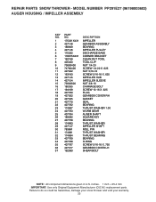
inches. 1 inch = 25.4 mm IMPORTANT: Use only Original Equipment Manufacturer (O.E.M.) replacement parts. REPAIR PARTS SNOW THROWER - MODEL NUMBER PP291E27 (96198003602) AUGER HOUSING / IMPELLER ASSEMBLY KEY NO. 1 2 3 4 5 6 7 8 9 10 11 12 13 14 15 16 17 18 19 20 21 22 23 24 25 26 27 ...28 29 30 31 32 33 34 35 36 37 PART NO. 175321X431 427148 188909 427146 175322 178675X431 192199 405400 73800400 74780426 427942...
inches. 1 inch = 25.4 mm IMPORTANT: Use only Original Equipment Manufacturer (O.E.M.) replacement parts. REPAIR PARTS SNOW THROWER - MODEL NUMBER PP291E27 (96198003602) AUGER HOUSING / IMPELLER ASSEMBLY KEY NO. 1 2 3 4 5 6 7 8 9 10 11 12 13 14 15 16 17 18 19 20 21 22 23 24 25 26 27 ...28 29 30 31 32 33 34 35 36 37 PART NO. 175321X431 427148 188909 427146 175322 178675X431 192199 405400 73800400 74780426 427942...

User Manual
Page 24
... in U.S. Failure to do so could be hazardous, damage your snow thrower and void your warranty. 24 REPAIR PARTS SNOW THROWER - MODEL NUMBER PP291E27 (96198003602) AUGER HOUSING / IMPELLER ASSEMBLY 2 3 1 1 2 3 01.07.024-B KEY NO. 1 2 3 PART NO. 420478 411939 179582 DESCRIPTION AUGER BEARING BEARING PLUG SCREW 5/16−18 X 1.00 4 4 01.11.001-B 3 2 3 KEY...
... in U.S. Failure to do so could be hazardous, damage your snow thrower and void your warranty. 24 REPAIR PARTS SNOW THROWER - MODEL NUMBER PP291E27 (96198003602) AUGER HOUSING / IMPELLER ASSEMBLY 2 3 1 1 2 3 01.07.024-B KEY NO. 1 2 3 PART NO. 420478 411939 179582 DESCRIPTION AUGER BEARING BEARING PLUG SCREW 5/16−18 X 1.00 4 4 01.11.001-B 3 2 3 KEY...
User Manual
Page 25
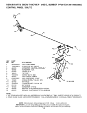
... 25 ALL ITEMS INDICATED WITH AN * ARE PROVIDED IN THE BAG OF ITEMS SHIPPED LOOSE WITH PRODUCT. 2. NOTE: All component dimensions given in U.S. REPAIR PARTS SNOW THROWER - MODEL NUMBER PP291E27 (96198003602) CONTROL PANEL / CHUTE 5 7 15 3 16 *14 *11 2 4 6 *10 KEY NO. 1 2 3 4 5 6 7 8 9 *10... *11 *12 *13 *14 15 16 PART NO. 435023X428 178633X428 420673 420325 414280 128415 17501010 430324 419822X431 179829 191730 72250505 751153 184505 420679 420672 ...
... 25 ALL ITEMS INDICATED WITH AN * ARE PROVIDED IN THE BAG OF ITEMS SHIPPED LOOSE WITH PRODUCT. 2. NOTE: All component dimensions given in U.S. REPAIR PARTS SNOW THROWER - MODEL NUMBER PP291E27 (96198003602) CONTROL PANEL / CHUTE 5 7 15 3 16 *14 *11 2 4 6 *10 KEY NO. 1 2 3 4 5 6 7 8 9 *10... *11 *12 *13 *14 15 16 PART NO. 435023X428 178633X428 420673 420325 414280 128415 17501010 430324 419822X431 179829 191730 72250505 751153 184505 420679 420672 ...
User Manual
Page 26
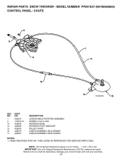
... to do so could be hazardous, damage your snow thrower and void your warranty. 26 MODEL NUMBER PP291E27 (96198003602) CONTROL PANEL / CHUTE 2 2 *3 1 *7 *6 *4 01.09.010-B *5 KEY NO. 1 2 *3 *4 *5 *6 *7 PART NO. 428272 17501010 420678 405932 420675 428273 428310 DESCRIPTION LEVER/CABLE ROTATOR ASSEMBLY SCREW 10-24 X .625 ROTATOR HEAD ROTATOR PIVOT BRACKET PULLEY PIVOT...
... to do so could be hazardous, damage your snow thrower and void your warranty. 26 MODEL NUMBER PP291E27 (96198003602) CONTROL PANEL / CHUTE 2 2 *3 1 *7 *6 *4 01.09.010-B *5 KEY NO. 1 2 *3 *4 *5 *6 *7 PART NO. 428272 17501010 420678 405932 420675 428273 428310 DESCRIPTION LEVER/CABLE ROTATOR ASSEMBLY SCREW 10-24 X .625 ROTATOR HEAD ROTATOR PIVOT BRACKET PULLEY PIVOT...
User Manual
Page 27
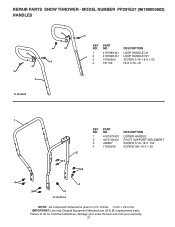
...NO. MODEL NUMBER PP291E27 (96198003602) HANDLES 4 4 3 2 01.08.004-B 3 4 4 3 3 KEY PART NO. Failure to do so could be hazardous, damage your snow thrower and void your warranty. 27 inches. 1 inch = 25.4 mm IMPORTANT: Use only Original Equipment Manufacturer (O.E.M.) replacement parts. DESCRIPTION 1 12 ... 419799X431 74780524 751153 LOOP HANDLE LH LOOP HANDLE RH SCREW 5/16−18 X 1.50 NUT 5/16−18 1 KEY NO. 1 2 3 4 PART NO. 419797X431 427513X431 428867 17000616 DESCRIPTION LOWER HANDLE PIVOT SUPPORT WELDMENT SCREW 5/16−18 X .750 SCREW 3/8−16 X 1.00 2 4 3 ...
...NO. MODEL NUMBER PP291E27 (96198003602) HANDLES 4 4 3 2 01.08.004-B 3 4 4 3 3 KEY PART NO. Failure to do so could be hazardous, damage your snow thrower and void your warranty. 27 inches. 1 inch = 25.4 mm IMPORTANT: Use only Original Equipment Manufacturer (O.E.M.) replacement parts. DESCRIPTION 1 12 ... 419799X431 74780524 751153 LOOP HANDLE LH LOOP HANDLE RH SCREW 5/16−18 X 1.50 NUT 5/16−18 1 KEY NO. 1 2 3 4 PART NO. 419797X431 427513X431 428867 17000616 DESCRIPTION LOWER HANDLE PIVOT SUPPORT WELDMENT SCREW 5/16−18 X .750 SCREW 3/8−16 X 1.00 2 4 3 ...


