
User Manual
Page 2
...in contact with a portable container, rather than from a gasoline dispenser nozzle. 2 5. Do not use on sidewalks, driveways and other engine parts become extremely hot during operation or while performing an adjustment or repair to make any adjustments while the engine (motor) is not possible, then... Never allow children to vibrate abnormally, stop the engine (motor), remove the wire from these areas. WARNING: Snow throwers have exposed rotating parts, which can get caught in the manual(s) before filling. 4. To avoid severe burns on contact, stay away from the spark plug, ...
...in contact with a portable container, rather than from a gasoline dispenser nozzle. 2 5. Do not use on sidewalks, driveways and other engine parts become extremely hot during operation or while performing an adjustment or repair to make any adjustments while the engine (motor) is not possible, then... Never allow children to vibrate abnormally, stop the engine (motor), remove the wire from these areas. WARNING: Snow throwers have exposed rotating parts, which can get caught in the manual(s) before filling. 4. To avoid severe burns on contact, stay away from the spark plug, ...
User Manual
Page 3
...PRODUCT SPECIFICATIONS 3 SERVICE AND ADJUSTMENTS 16-18 CUSTOMER RESPONSIBILITIES 3 STORAGE 19 ASSEMBLY / PRE-OPERATION 4-7 TROUBLESHOOTING 20 OPERATION 8-13 REPAIR PARTS 22-42 MAINTENANCE 14-15 3 WARRANTY BACK PAGE Never direct the discharge toward people or areas where property damage can occur. ...center. When cleaning, repairing or inspecting the snow thrower, stop the engine and make certain the collector/impeller and all moving parts have stopped. To clear the chute: 1. Never store the machine with the rotating impeller inside a building where ignition sources ...
...PRODUCT SPECIFICATIONS 3 SERVICE AND ADJUSTMENTS 16-18 CUSTOMER RESPONSIBILITIES 3 STORAGE 19 ASSEMBLY / PRE-OPERATION 4-7 TROUBLESHOOTING 20 OPERATION 8-13 REPAIR PARTS 22-42 MAINTENANCE 14-15 3 WARRANTY BACK PAGE Never direct the discharge toward people or areas where property damage can occur. ...center. When cleaning, repairing or inspecting the snow thrower, stop the engine and make certain the collector/impeller and all moving parts have stopped. To clear the chute: 1. Never store the machine with the rotating impeller inside a building where ignition sources ...
User Manual
Page 4
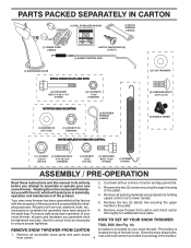
...holding speed control rod to the pallet. 6. To ensure safe and proper operation of the belt cover. Remove all parts and hardware you in the parts bag. The toolbox is provided on top of your snow thrower. HOW TO SET UP YOUR SNOW THROWER TOOL BOX... (See Fig. 10) REMOVE SNOW THROWER FROM CARTON A toolbox is 1. Remove the two (2) plastic ties securing the upper handle to lower handle. 5. PARTS PACKED SEPARATELY IN CARTON (1) FUEL STABILIZER PACKET (1) MULTIWRENCH (180684) (1) POWER CORD (198563) SAFTEY IGNITION KEY(S) (193071) (1) AUGER CONTROL ROD (1) DISCHARGE ...
...holding speed control rod to the pallet. 6. To ensure safe and proper operation of the belt cover. Remove all parts and hardware you in the parts bag. The toolbox is provided on top of your snow thrower. HOW TO SET UP YOUR SNOW THROWER TOOL BOX... (See Fig. 10) REMOVE SNOW THROWER FROM CARTON A toolbox is 1. Remove the two (2) plastic ties securing the upper handle to lower handle. 5. PARTS PACKED SEPARATELY IN CARTON (1) FUEL STABILIZER PACKET (1) MULTIWRENCH (180684) (1) POWER CORD (198563) SAFTEY IGNITION KEY(S) (193071) (1) AUGER CONTROL ROD (1) DISCHARGE ...
User Manual
Page 5
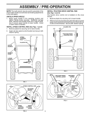
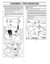
... and secure with retainer spring. With top end of rod positioned under left side of control panel, push rod down and insert top end of parts.
... and secure with retainer spring. With top end of rod positioned under left side of control panel, push rod down and insert top end of parts.
User Manual
Page 6
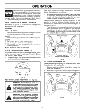
...loop opening toward front of rod into control arm with retainer spring. Place discharge chute assembly on top of chute base with holes in your parts bag may be used to align square and pin on rod and insert end of snow thrower. 2. If necessary, rotate chute assembly to ... bracket. Position chute rotator head over chute bracket. With top end of rod positioned under right side of control panel, push down on underside of parts and retrieve the auger control rod from bag of chute rotator head with discharge opening up as shown. (See Fig. 5) 3. ASSEMBLY / PRE-OPERATION ...
...loop opening toward front of rod into control arm with retainer spring. Place discharge chute assembly on top of chute base with holes in your parts bag may be used to align square and pin on rod and insert end of snow thrower. 2. If necessary, rotate chute assembly to ... bracket. Position chute rotator head over chute bracket. With top end of rod positioned under right side of control panel, push down on underside of parts and retrieve the auger control rod from bag of chute rotator head with discharge opening up as shown. (See Fig. 5) 3. ASSEMBLY / PRE-OPERATION ...
User Manual
Page 10
... to unclog the chute and/or auger. OFF FULL FIG. 11 TO CONTROL SNOW DISCHARGE (See Fig. 12) WARNING: Snow throwers have exposed rotating parts, which can result in desired position. ENGINE 1. Keep the area of operation clear of the chute deflector. Use the clean-out tool, NOT YOUR...downward on the engine. The DISTANCE that snow is thrown is controlled by the position of all persons, small children and pets at all moving parts to stop engine. AUGER CONTROL LEVER FIG. 13 10 AUGER • Release the auger control lever to stop the forward or reverse movement ...
... to unclog the chute and/or auger. OFF FULL FIG. 11 TO CONTROL SNOW DISCHARGE (See Fig. 12) WARNING: Snow throwers have exposed rotating parts, which can result in desired position. ENGINE 1. Keep the area of operation clear of the chute deflector. Use the clean-out tool, NOT YOUR...downward on the engine. The DISTANCE that snow is thrown is controlled by the position of all persons, small children and pets at all moving parts to stop engine. AUGER CONTROL LEVER FIG. 13 10 AUGER • Release the auger control lever to stop the forward or reverse movement ...

User Manual
Page 11
.... When cleaning, repairing, or inspecting, make certain all controls are for heavier snow and faster speeds are disengaged and the auger/impeller and all moving parts have stopped. NOTE: When both traction drive and auger control levers are located on the underside of each handle. The triggers are engaged, the traction...
.... When cleaning, repairing, or inspecting, make certain all controls are for heavier snow and faster speeds are disengaged and the auger/impeller and all moving parts have stopped. NOTE: When both traction drive and auger control levers are located on the underside of each handle. The triggers are engaged, the traction...
User Manual
Page 14
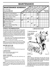
Some adjustments will help your snow thrower well lubricated (See "LUBRICATION CHART"). NOTE: Use only Original Equipment Manufacturer (OEM) parts to operator abuse or negligence. Failure to do so can cause personal injury or damage to 14 the snow thrower. Check controls... made periodically to be checked at least once each season. • Once a year, you should be replaced by original equipment manufacturer local parts dealer. Auger grease fittings Engine oil SNOW THROWER Always observe the safety rules when performing any maintenance. LUBRICATION CHART SAE 5W-30 Motor Oil ...
Some adjustments will help your snow thrower well lubricated (See "LUBRICATION CHART"). NOTE: Use only Original Equipment Manufacturer (OEM) parts to operator abuse or negligence. Failure to do so can cause personal injury or damage to 14 the snow thrower. Check controls... made periodically to be checked at least once each season. • Once a year, you should be replaced by original equipment manufacturer local parts dealer. Auger grease fittings Engine oil SNOW THROWER Always observe the safety rules when performing any maintenance. LUBRICATION CHART SAE 5W-30 Motor Oil ...
User Manual
Page 16
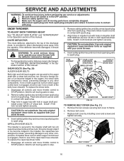
...contact with hole in impeller hub with spark plug. 3. WARNING: To avoid serious injury, never operate your snow thrower. 4. Disengage all moving parts have sheared. Align holes in auger shaft and install a new 1/4-20 x 2" shear bolt. Insert safety ignition key and reconnect spark plug...damage to any service or adjustments: 1. Make sure the augers and all controls and move throttle control to STOP position. Wait for all moving parts to spark plug. 1/4-20 LOCKNUT 1/4-20 x 1-5/8 CAPSCREW / SHEAR BOLT IMPELLER HUB IMPELLER SHAFT 1/4-20 x 2 SHOULDER / SHEAR BOLT AUGER...
...contact with hole in impeller hub with spark plug. 3. WARNING: To avoid serious injury, never operate your snow thrower. 4. Disengage all moving parts have sheared. Align holes in auger shaft and install a new 1/4-20 x 2" shear bolt. Insert safety ignition key and reconnect spark plug...damage to any service or adjustments: 1. Make sure the augers and all controls and move throttle control to STOP position. Wait for all moving parts to spark plug. 1/4-20 LOCKNUT 1/4-20 x 1-5/8 CAPSCREW / SHEAR BOLT IMPELLER HUB IMPELLER SHAFT 1/4-20 x 2 SHOULDER / SHEAR BOLT AUGER...
User Manual
Page 18
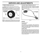
... the wheel hub (if equipped). CARBURETOR Your carburetor is snug. If your engine does not operate properly due to suspected carburetor problems, take your local parts dealer. Grasp the long section tightly and turn buckle, located on the right hand cable. SERVICE AND ADJUSTMENTS TO REMOVE WHEELS (See Fig. 23) •...
... the wheel hub (if equipped). CARBURETOR Your carburetor is snug. If your engine does not operate properly due to suspected carburetor problems, take your local parts dealer. Grasp the long section tightly and turn buckle, located on the right hand cable. SERVICE AND ADJUSTMENTS TO REMOVE WHEELS (See Fig. 23) •...
User Manual
Page 19
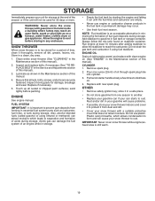
... the Maintenance section of this manual. 4. IMPORTANT: Never cover snow thrower while engine/exhaust area is an acceptable alternative in essential fuel system parts such as on stabilizer container. Be sure that does not retain moisture. ENGINE See engine manual. FUEL SYSTEM IMPORTANT: It is to be... forming in minimizing the formation of time, clean it from dust and dirt. • Cover your snow thrower to rust. Inspect moving parts for storage at least 10 minutes after adding stabilizer to allow the stabilizer to cool before painting. Run engine at the end of acids...
... the Maintenance section of this manual. 4. IMPORTANT: Never cover snow thrower while engine/exhaust area is an acceptable alternative in essential fuel system parts such as on stabilizer container. Be sure that does not retain moisture. ENGINE See engine manual. FUEL SYSTEM IMPORTANT: It is to be... forming in minimizing the formation of time, clean it from dust and dirt. • Cover your snow thrower to rust. Inspect moving parts for storage at least 10 minutes after adding stabilizer to allow the stabilizer to cool before painting. Run engine at the end of acids...
User Manual
Page 20
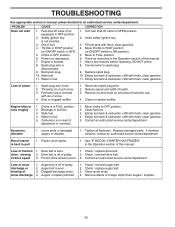
..., clean gasoline. Blockage in OFF position. 6. Carburetor is off of pulley. 2. Contact an authorized service center/department. Replace damaged parts. Recoil starter is worn. 1. Drive belt is hard to pull 1. Check / replace auger belt. 3. TROUBLESHOOTING See appropriate section ...refill with ice or snow. 4. Clean or replace muffler. Empty fuel tank & carburetor, refill with fresh, clean gasoline. 11. Loose parts or damaged augers or impeller. 1. If vibration remains, contact an authorized service center/department. Drive belt is in FULL position. 2. Contact...
..., clean gasoline. Blockage in OFF position. 6. Carburetor is off of pulley. 2. Contact an authorized service center/department. Replace damaged parts. Recoil starter is worn. 1. Drive belt is hard to pull 1. Check / replace auger belt. 3. TROUBLESHOOTING See appropriate section ...refill with ice or snow. 4. Clean or replace muffler. Empty fuel tank & carburetor, refill with fresh, clean gasoline. 11. Loose parts or damaged augers or impeller. 1. If vibration remains, contact an authorized service center/department. Drive belt is in FULL position. 2. Contact...
User Manual
Page 22
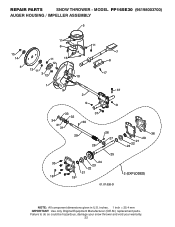
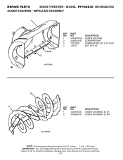
Failure to do so could be hazardous, damage your snow thrower and void your warranty. 22 REPAIR PARTS SNOW THROWER - MODEL PP165E30 (96198003700) AUGER HOUSING / IMPELLER ASSEMBLY 5 15 14 4 11 6 11 16 12 13 11 3 12 10 11 7 8 17 1 9 37 2 9 9 33 37 32 34 30 31 31 29 28 26 27 36 20 21 22 23 25 35 24 23 22 21 18 19 2 (EXPLODED) 01.07.026-D NOTE: All component dimensions given in U.S. inches. 1 inch = 25.4 mm IMPORTANT: Use only Original Equipment Manufacturer (O.E.M.) replacement parts.
Failure to do so could be hazardous, damage your snow thrower and void your warranty. 22 REPAIR PARTS SNOW THROWER - MODEL PP165E30 (96198003700) AUGER HOUSING / IMPELLER ASSEMBLY 5 15 14 4 11 6 11 16 12 13 11 3 12 10 11 7 8 17 1 9 37 2 9 9 33 37 32 34 30 31 31 29 28 26 27 36 20 21 22 23 25 35 24 23 22 21 18 19 2 (EXPLODED) 01.07.026-D NOTE: All component dimensions given in U.S. inches. 1 inch = 25.4 mm IMPORTANT: Use only Original Equipment Manufacturer (O.E.M.) replacement parts.

User Manual
Page 23
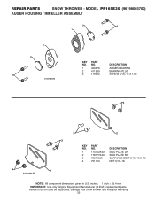
MODEL PP165E30 (96198003700) AUGER HOUSING / IMPELLER ASSEMBLY KEY NO. 1 2 3 4 5 6 7 8 9 10 11 12 13 14 15 16 17 18 19 20 21 22 23 24 25 26 27 28 29 30 31 32 33 34 35 36 37 PART NO. 175321X431 427148 188909 427146 175322 178675X431 192199 405400 73800400 74780426 ... O-RING SCREW 5/16-18 X .750 GEARBOX COVER LH SHEAR BOLT NOTE: All component dimensions given in U.S. REPAIR PARTS SNOW THROWER - inches. 1 inch = 25.4 mm IMPORTANT: Use only Original Equipment Manufacturer (O.E.M.) replacement parts. Failure to do so could be hazardous, damage your snow thrower and void your warranty. 23
MODEL PP165E30 (96198003700) AUGER HOUSING / IMPELLER ASSEMBLY KEY NO. 1 2 3 4 5 6 7 8 9 10 11 12 13 14 15 16 17 18 19 20 21 22 23 24 25 26 27 28 29 30 31 32 33 34 35 36 37 PART NO. 175321X431 427148 188909 427146 175322 178675X431 192199 405400 73800400 74780426 ... O-RING SCREW 5/16-18 X .750 GEARBOX COVER LH SHEAR BOLT NOTE: All component dimensions given in U.S. REPAIR PARTS SNOW THROWER - inches. 1 inch = 25.4 mm IMPORTANT: Use only Original Equipment Manufacturer (O.E.M.) replacement parts. Failure to do so could be hazardous, damage your snow thrower and void your warranty. 23
User Manual
Page 24
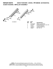
MODEL PP165E30 (96198003700) AUGER HOUSING / IMPELLER ASSEMBLY 1 3 (5x) 4 (5x) 2 KEY NO. 1 2 3 4 PART NO. 404930X428 404933X431 72270505 155377 DESCRIPTION AUGER HOUSING SCRAPPER BAR CARRIAGE BOLT 5/16−18 X .625 NUT 5/16−18 01.07.003-A 2 1 KEY NO. 1 2 PART NO. 420497X431 420498X431 DESCRIPTION AUGER ASSEMBLY 30... LH AUGER ASSEMBLY 30 RH 01.07.019-A NOTE: All component dimensions given in U.S. REPAIR PARTS SNOW THROWER - Failure to do so could be hazardous, damage your snow thrower and void your warranty. 24 inches. 1...
MODEL PP165E30 (96198003700) AUGER HOUSING / IMPELLER ASSEMBLY 1 3 (5x) 4 (5x) 2 KEY NO. 1 2 3 4 PART NO. 404930X428 404933X431 72270505 155377 DESCRIPTION AUGER HOUSING SCRAPPER BAR CARRIAGE BOLT 5/16−18 X .625 NUT 5/16−18 01.07.003-A 2 1 KEY NO. 1 2 PART NO. 420497X431 420498X431 DESCRIPTION AUGER ASSEMBLY 30... LH AUGER ASSEMBLY 30 RH 01.07.019-A NOTE: All component dimensions given in U.S. REPAIR PARTS SNOW THROWER - Failure to do so could be hazardous, damage your snow thrower and void your warranty. 24 inches. 1...
User Manual
Page 25
MODEL PP165E30 (96198003700) AUGER HOUSING / IMPELLER ASSEMBLY 2 3 1 1 2 3 01.07.024-B KEY NO. 1 2 3 PART NO. 420478 411939 179582 DESCRIPTION AUGER BEARING BEARING PLUG SCREW 5/16−18 X 1.00 4 4 01.11.001-B 3 1 3 2 KEY NO. 1 2 3 4 PART NO. 174762X431 178777X431 72270506 751153 DESCRIPTION SKID PLATE LH SKID PLATE RH CARRIAGE BOLT 5/16−...given in U.S. Failure to do so could be hazardous, damage your snow thrower and void your warranty. 25 REPAIR PARTS SNOW THROWER - inches. 1 inch = 25.4 mm IMPORTANT: Use only Original Equipment Manufacturer (O.E.M.) replacement...
MODEL PP165E30 (96198003700) AUGER HOUSING / IMPELLER ASSEMBLY 2 3 1 1 2 3 01.07.024-B KEY NO. 1 2 3 PART NO. 420478 411939 179582 DESCRIPTION AUGER BEARING BEARING PLUG SCREW 5/16−18 X 1.00 4 4 01.11.001-B 3 1 3 2 KEY NO. 1 2 3 4 PART NO. 174762X431 178777X431 72270506 751153 DESCRIPTION SKID PLATE LH SKID PLATE RH CARRIAGE BOLT 5/16−...given in U.S. Failure to do so could be hazardous, damage your snow thrower and void your warranty. 25 REPAIR PARTS SNOW THROWER - inches. 1 inch = 25.4 mm IMPORTANT: Use only Original Equipment Manufacturer (O.E.M.) replacement...
User Manual
Page 26
inches. 1 inch = 25.4 mm IMPORTANT: Use only Original Equipment Manufacturer (O.E.M.) replacement parts. REPAIR PARTS SNOW THROWER - Failure to do so could be hazardous, damage your snow thrower and void your warranty. 26 MODEL PP165E30 (96198003700) AUGER HOUSING / IMPELLER ASSEMBLY 2 1 3 4 2 5 01.16.001-B 5 4 3 1 KEY NO. 1 2 3 4 5 PART NO. 181160X431 72270506 179246 10040500 128638 DESCRIPTION DRIFT CUTTER BAR CARRIAGE BOLT 5/16−18 X .750 PLASTIC WASHER LOCKWASHER 5/16 NUT 5/16−18 NOTE: All component dimensions given in U.S.
inches. 1 inch = 25.4 mm IMPORTANT: Use only Original Equipment Manufacturer (O.E.M.) replacement parts. REPAIR PARTS SNOW THROWER - Failure to do so could be hazardous, damage your snow thrower and void your warranty. 26 MODEL PP165E30 (96198003700) AUGER HOUSING / IMPELLER ASSEMBLY 2 1 3 4 2 5 01.16.001-B 5 4 3 1 KEY NO. 1 2 3 4 5 PART NO. 181160X431 72270506 179246 10040500 128638 DESCRIPTION DRIFT CUTTER BAR CARRIAGE BOLT 5/16−18 X .750 PLASTIC WASHER LOCKWASHER 5/16 NUT 5/16−18 NOTE: All component dimensions given in U.S.
User Manual
Page 27
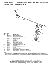
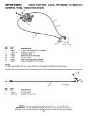
... to do so could be hazardous, damage your snow thrower and void your warranty. 27 MODEL PP165E30 (96198003700) CONTROL PANEL / DISCHARGE CHUTE 5 7 15 3 16 *14 *11 2 4 6 *10 KEY PART 6 NO. DESCRIPTION 1 435023X428 CHUTE WELDMENT 1 2 178633X428 DEFLECTOR WELDMENT 3 420673 DEFLECTOR CONTROL ASSEMBLY...12 72250505 CARRIAGE BOLT 3/8-16 X .625 *13 751153 NUT 5/16-18 *14 184505 DEFLECTOR SPRING 15 420679 (SERVICE PART) DEFLECTOR CONTROL 16 420672 (SERVICE PART) DEFLECTOR CABLE BLACK *13 *12 9 8 01.09.015-B NOTE: 1. NOTE: All component dimensions given in U.S....
... to do so could be hazardous, damage your snow thrower and void your warranty. 27 MODEL PP165E30 (96198003700) CONTROL PANEL / DISCHARGE CHUTE 5 7 15 3 16 *14 *11 2 4 6 *10 KEY PART 6 NO. DESCRIPTION 1 435023X428 CHUTE WELDMENT 1 2 178633X428 DEFLECTOR WELDMENT 3 420673 DEFLECTOR CONTROL ASSEMBLY...12 72250505 CARRIAGE BOLT 3/8-16 X .625 *13 751153 NUT 5/16-18 *14 184505 DEFLECTOR SPRING 15 420679 (SERVICE PART) DEFLECTOR CONTROL 16 420672 (SERVICE PART) DEFLECTOR CABLE BLACK *13 *12 9 8 01.09.015-B NOTE: 1. NOTE: All component dimensions given in U.S....
User Manual
Page 28
... warranty. 28 inches. 1 inch = 25.4 mm IMPORTANT: Use only Original Equipment Manufacturer (O.E.M.) replacement parts. MODEL PP165E30 (96198003700) CONTROL PANEL / DISCHARGE CHUTE 2 2 *3 1 *7 *6 KEY NO. 1 2 *3 *4 *5 *6 *7 PART NO. 428272 17501010 420678 405932 420675 428273 428310 DESCRIPTION LEVER/CABLE ROTATOR ASSEMBLY SCREW 10-24 X ....SHIELD *4 01.09.010-B *5 NOTES: 1. ITEMS INDICATED WITH AN * ARE LISTED AS REFERENCE FOR SERVICE PARTS ONLY. 2 1 KEY NO. 1 2 PART NO. 421249 74041024 DESCRIPTION STEER CABLE SCREW 10−24 X 1.50 01.15.009-A NOTE: All component dimensions given...
... warranty. 28 inches. 1 inch = 25.4 mm IMPORTANT: Use only Original Equipment Manufacturer (O.E.M.) replacement parts. MODEL PP165E30 (96198003700) CONTROL PANEL / DISCHARGE CHUTE 2 2 *3 1 *7 *6 KEY NO. 1 2 *3 *4 *5 *6 *7 PART NO. 428272 17501010 420678 405932 420675 428273 428310 DESCRIPTION LEVER/CABLE ROTATOR ASSEMBLY SCREW 10-24 X ....SHIELD *4 01.09.010-B *5 NOTES: 1. ITEMS INDICATED WITH AN * ARE LISTED AS REFERENCE FOR SERVICE PARTS ONLY. 2 1 KEY NO. 1 2 PART NO. 421249 74041024 DESCRIPTION STEER CABLE SCREW 10−24 X 1.50 01.15.009-A NOTE: All component dimensions given...
User Manual
Page 29
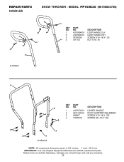
... SCREW 5/16−18 X 1.50 NUT 5/16−18 01.08.004-B 1 KEY PART 2 NO. MODEL PP165E30 (96198003700) 4 4 3 2 3 4 4 3 3 KEY PART NO. NO. NO. Failure to do so could be hazardous, damage your snow thrower and void your warranty. 29 REPAIR PARTS HANDLES SNOW THROWER - DESCRIPTION 1 419797X431 LOWER HANDLE 4 2 427513X431 PIVOT SUPPORT WELDMENT 3 428867 SCREW...
... SCREW 5/16−18 X 1.50 NUT 5/16−18 01.08.004-B 1 KEY PART 2 NO. MODEL PP165E30 (96198003700) 4 4 3 2 3 4 4 3 3 KEY PART NO. NO. NO. Failure to do so could be hazardous, damage your snow thrower and void your warranty. 29 REPAIR PARTS HANDLES SNOW THROWER - DESCRIPTION 1 419797X431 LOWER HANDLE 4 2 427513X431 PIVOT SUPPORT WELDMENT 3 428867 SCREW...


