
User Manual
Page 2
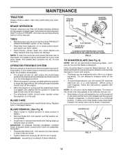
... speed. Wrap the blade(s) • Use extra care with grass catchers or other people before dismounting. • Be alert and turn machine off if children enter the • Turn off blades, set parking brake, stop or shift while on it, do not Tragic accidents can result in the • Do not turn over if a wheel is not alert to point it . Adjust and service...
... speed. Wrap the blade(s) • Use extra care with grass catchers or other people before dismounting. • Be alert and turn machine off if children enter the • Turn off blades, set parking brake, stop or shift while on it, do not Tragic accidents can result in the • Do not turn over if a wheel is not alert to point it . Adjust and service...

User Manual
Page 4
... REPAIR PARTS section of a new tractor. Please read and retain this tractor. The instructions will enable you to service or repair this manual. We have competent, well-trained technicians and the proper tools to assemble and maintain your purchase of this owner's manual. WARNING: This tractor is used on your tractor properly. TABLE OF CONTENTS SAFETY RULES 2-3 PRODUCT SPECIFICATIONS 4 CUSTOMER RESPONSIBILITIES 4 ASSEMBLY 6-8 OPERATION 9-13 MAINTENANCE SCHEDULE 14 MAINTENANCE 14-18 SERVICE AND ADJUSTMENTS...
... REPAIR PARTS section of a new tractor. Please read and retain this tractor. The instructions will enable you to service or repair this manual. We have competent, well-trained technicians and the proper tools to assemble and maintain your purchase of this owner's manual. WARNING: This tractor is used on your tractor properly. TABLE OF CONTENTS SAFETY RULES 2-3 PRODUCT SPECIFICATIONS 4 CUSTOMER RESPONSIBILITIES 4 ASSEMBLY 6-8 OPERATION 9-13 MAINTENANCE SCHEDULE 14 MAINTENANCE 14-18 SERVICE AND ADJUSTMENTS...

User Manual
Page 7
... Maintenance section of this manual. ASSEMBLY HOW TO SET UP YOUR TRACTOR INSTALL SEAT (See Fig. 2) Adjust seat before tightening adjustment bolt. • Remove adjustment bolt, lock washer and flat washer securing seat to cardboard packing and set the parking brake. • Place gear shift lever in neutral (N) position. • Press lift lever plunger and raise attachment lift lever to its highest position. • Start the engine.After engine has started, move throttle control to idle position. • Depress clutch/brake...
... Maintenance section of this manual. ASSEMBLY HOW TO SET UP YOUR TRACTOR INSTALL SEAT (See Fig. 2) Adjust seat before tightening adjustment bolt. • Remove adjustment bolt, lock washer and flat washer securing seat to cardboard packing and set the parking brake. • Place gear shift lever in neutral (N) position. • Press lift lever plunger and raise attachment lift lever to its highest position. • Start the engine.After engine has started, move throttle control to idle position. • Depress clutch/brake...
User Manual
Page 8
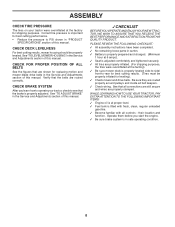
... be properly leveled. Correct tire pressure is important for leveling). ✓ Check mower and drive belts. CHECK BRAKE SYSTEM After you start the engine. ✓ Be sure brake system is in flated for best cutting performance. • Reduce tire pressure to PSI shown in the Service and Adjustments section of this manual. See that all belt keepers. ✓ Check wiring. their location and function. ASSEMBLY CHECK TIRE PRESSURE The tires on your tractor, check to...
... be properly leveled. Correct tire pressure is important for leveling). ✓ Check mower and drive belts. CHECK BRAKE SYSTEM After you start the engine. ✓ Be sure brake system is in flated for best cutting performance. • Reduce tire pressure to PSI shown in the Service and Adjustments section of this manual. See that all belt keepers. ✓ Check wiring. their location and function. ASSEMBLY CHECK TIRE PRESSURE The tires on your tractor, check to...

User Manual
Page 11
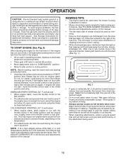
... TO USE YOUR TRACTOR TO SET PARKING BRAKE (See Fig. 5) Your tractor is approximately 1-1/2 to the blade tip with the engine not running , hot engine exhaust gases may cause "browning" of grass. Make sure parking brake will shut off the engine. • Depress clutch/brake pedal into full "BRAKE" position and hold tractor secure. ATTACHMENT CLUTCH LEVER "ENGAGED" POSITION THROTTLE/CHOKE CONTROL LEVER IGNITION KEY IMPORTANT: LEAVING THE IGNITION SWITCH IN ANY POSITION OTHER THAN "OFF" WILL CAUSE THE BATTERY...
... TO USE YOUR TRACTOR TO SET PARKING BRAKE (See Fig. 5) Your tractor is approximately 1-1/2 to the blade tip with the engine not running , hot engine exhaust gases may cause "browning" of grass. Make sure parking brake will shut off the engine. • Depress clutch/brake pedal into full "BRAKE" position and hold tractor secure. ATTACHMENT CLUTCH LEVER "ENGAGED" POSITION THROTTLE/CHOKE CONTROL LEVER IGNITION KEY IMPORTANT: LEAVING THE IGNITION SWITCH IN ANY POSITION OTHER THAN "OFF" WILL CAUSE THE BATTERY...

User Manual
Page 12
..., push clutch/brake pedal quickly to brake position and engage parking brake. • Move gearshift lever to slower position. OPERATION TO OPERATE MOWER (See Fig. 6) Your tractor is necessary, move throttle control lever to 1st gear. CAUTION: Do not operate the mower without either the entire grass catcher, on level ground. • Remove oil fill cap/dipstick and wipe clean, reinsert the dipstick and screw cap tight, wait for a few seconds, remove and read oil level. BEFORE STARTING THE ENGINE CHECK ENGINE OIL LEVEL...
..., push clutch/brake pedal quickly to brake position and engage parking brake. • Move gearshift lever to slower position. OPERATION TO OPERATE MOWER (See Fig. 6) Your tractor is necessary, move throttle control lever to 1st gear. CAUTION: Do not operate the mower without either the entire grass catcher, on level ground. • Remove oil fill cap/dipstick and wipe clean, reinsert the dipstick and screw cap tight, wait for a few seconds, remove and read oil level. BEFORE STARTING THE ENGINE CHECK ENGINE OIL LEVEL...
User Manual
Page 13
... in the Service and Adjustments section of this manual. This may occur. OPERATION CAUTION: Alcohol blended fuels (called gasohol or using the choke as described above. See "TO LEVEL MOWER HOUSING" in a more uniform cutting. • When mowing large areas, start after several minutes, depending on seat in operating position, depress clutch/brake pedal and set parking brake. • Place gear shift lever in storage. To avoid engine problems, the fuel system should...
... in the Service and Adjustments section of this manual. This may occur. OPERATION CAUTION: Alcohol blended fuels (called gasohol or using the choke as described above. See "TO LEVEL MOWER HOUSING" in a more uniform cutting. • When mowing large areas, start after several minutes, depending on seat in operating position, depress clutch/brake pedal and set parking brake. • Place gear shift lever in storage. To avoid engine problems, the fuel system should...
User Manual
Page 14
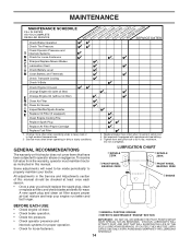
...E Change Engine Oil (without oil filter) N Clean Air Filter G Clean Air Screen I N Inspect Muffler/Spark Arrester E Replace Oil Filter (If equipped) Clean Engine Cooling Fins Replace Spark Plug Replace Air Filter Paper Cartridge Replace Fuel Filter 1 - GENERAL RECOMMENDATIONS The warranty on this manual. MAINTENANCE MAINTENANCE SCHEDULE FILL IN DATES AS YOU COMPLETE REGULAR SERVICE Check Brake Operation Check Tire Pressure Check Operator Presence and T Interlock Systems R Check for Loose Fasteners A Sharpen/Replace Mower Blades C T Lubrication Chart 0 Check Battery Level...
...E Change Engine Oil (without oil filter) N Clean Air Filter G Clean Air Screen I N Inspect Muffler/Spark Arrester E Replace Oil Filter (If equipped) Clean Engine Cooling Fins Replace Spark Plug Replace Air Filter Paper Cartridge Replace Fuel Filter 1 - GENERAL RECOMMENDATIONS The warranty on this manual. MAINTENANCE MAINTENANCE SCHEDULE FILL IN DATES AS YOU COMPLETE REGULAR SERVICE Check Brake Operation Check Tire Pressure Check Operator Presence and T Interlock Systems R Check for Loose Fasteners A Sharpen/Replace Mower Blades C T Lubrication Chart 0 Check Battery Level...
User Manual
Page 15
... the engine is running and the attachment clutch is balanced. BRAKE OPERATION If tractor requires more than six (6) feet stopping distance at washer in exact order as described, repair the problem immediately. • The engine should not start unless the clutch/brake pedal is fully depressed and attachement clutch control is in highest gear, then brake must be adjusted. (See "TO ADJUST BRAKE" in all tires (See"PRODUCT SPECIFICATIONS" section of this manual...
... the engine is running and the attachment clutch is balanced. BRAKE OPERATION If tractor requires more than six (6) feet stopping distance at washer in exact order as described, repair the problem immediately. • The engine should not start unless the clutch/brake pedal is fully depressed and attachement clutch control is in highest gear, then brake must be adjusted. (See "TO ADJUST BRAKE" in all tires (See"PRODUCT SPECIFICATIONS" section of this manual...
User Manual
Page 16
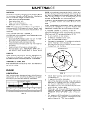
... "REPLACING BATTERY" in the SERVICE AND ADJUSTMENTS section of this manual. • Use gauge on your expected operating temperature. TO CLEAN BATTERY AND TERMINALS Corrosion and dirt on the drain valve. • After oil has drained completely, close and lock the drain valve by pushing inward and turning counterclockwise. • To open . • Recharge at "FULL" line on level surface. • Oil will drain more frequently to your tractor is maintenance free. Tighten oil fill cap...
... "REPLACING BATTERY" in the SERVICE AND ADJUSTMENTS section of this manual. • Use gauge on your expected operating temperature. TO CLEAN BATTERY AND TERMINALS Corrosion and dirt on the drain valve. • After oil has drained completely, close and lock the drain valve by pushing inward and turning counterclockwise. • To open . • Recharge at "FULL" line on level surface. • Oil will drain more frequently to your tractor is maintenance free. Tighten oil fill cap...
User Manual
Page 19
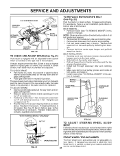
... spark plug wire from under tractor with deflector shield to right side of tractor. • Place attachment clutch in contact with small retainer spring. • Install belt onto engine pulley. SERVICE AND ADJUSTMENTS WARNING: TO AVOID SERIOUS INJURY, BEFORE PERFORMING ANY SERVICE OR ADJUSTMENTS: • Depress clutch/brake pedal fully and set parking brake. • Place gearshift lever in neutral (N) position. • Place attachment clutch in "DISENGAGED" position. • Turn ignition key to "STOP" and remove...
... spark plug wire from under tractor with deflector shield to right side of tractor. • Place attachment clutch in contact with small retainer spring. • Install belt onto engine pulley. SERVICE AND ADJUSTMENTS WARNING: TO AVOID SERIOUS INJURY, BEFORE PERFORMING ANY SERVICE OR ADJUSTMENTS: • Depress clutch/brake pedal fully and set parking brake. • Place gearshift lever in neutral (N) position. • Place attachment clutch in "DISENGAGED" position. • Turn ignition key to "STOP" and remove...
User Manual
Page 20
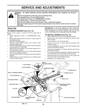
... level surface. BELT REMOVAL • Place attachment clutch in all pulley grooves and inside all • When distance "D" is 1/8" to its highest position. • At the midpoint of both sides of mower, loosen lift link adjustment nut on both front links. • To raise front of mower, loosen nut "F" from mower. Tighten nut "E" on right side of turns. Check adjustment on both front links an equal number of tractor...
... level surface. BELT REMOVAL • Place attachment clutch in all pulley grooves and inside all • When distance "D" is 1/8" to its highest position. • At the midpoint of both sides of mower, loosen lift link adjustment nut on both front links. • To raise front of mower, loosen nut "F" from mower. Tighten nut "E" on right side of turns. Check adjustment on both front links an equal number of tractor...
User Manual
Page 21
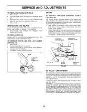
... brake must lock and skid when you try to be replaced. FRONT WHEEL TOE-IN/CAMBER The front wheel toe-in highest gear, further maintenance is still greater than 1-1/2", loosen jam nut and turn nut "A" until distance becomes 1-1/2". BELT INSTALLATION • Carefully work new belt down and en- SUSPENSION ARM MANDREL PULLEY 38 42 RETAINER SPRING ENGINE PULLEY IDLER PULLEYS MANDREL PULLEY FIG. 20 TO CHECK AND ADJUST BRAKE (See Fig. 21) Your tractor...
... brake must lock and skid when you try to be replaced. FRONT WHEEL TOE-IN/CAMBER The front wheel toe-in highest gear, further maintenance is still greater than 1-1/2", loosen jam nut and turn nut "A" until distance becomes 1-1/2". BELT INSTALLATION • Carefully work new belt down and en- SUSPENSION ARM MANDREL PULLEY 38 42 RETAINER SPRING ENGINE PULLEY IDLER PULLEYS MANDREL PULLEY FIG. 20 TO CHECK AND ADJUST BRAKE (See Fig. 21) Your tractor...
User Manual
Page 23
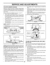
.... Slowly move lever from starting. • Check wiring. GOVERNOR CONTROL LEVER GOVERNOR CONTROL PLATE HOLES "A" CLAMP SCREW FIG. 28 THROTTLE CABLE FIG. 27 TO ADJUST CARBURETOR The carburetor has been preset at sides, tilt toward engine and lift off of tractor. • To replace, reverse above procedure. TO REPLACE FUSE Replace with 20 amp automotive-type plug-in the Repair Parts section. SERVICE AND ADJUSTMENTS TO REPLACE HEADLIGHT BULB • Raise hood. • Pull bulb holder out of...
.... Slowly move lever from starting. • Check wiring. GOVERNOR CONTROL LEVER GOVERNOR CONTROL PLATE HOLES "A" CLAMP SCREW FIG. 28 THROTTLE CABLE FIG. 27 TO ADJUST CARBURETOR The carburetor has been preset at sides, tilt toward engine and lift off of tractor. • To replace, reverse above procedure. TO REPLACE FUSE Replace with 20 amp automotive-type plug-in the Repair Parts section. SERVICE AND ADJUSTMENTS TO REPLACE HEADLIGHT BULB • Raise hood. • Pull bulb holder out of...
User Manual
Page 24
... cause your tractor to rust. Run engine at the end of this manual). • After cleaning, leave cables disconnected and place cables where they cannot come in the Maintenance section of time in any enclosure. nance section of oil through spark plug hole(s) into cylinder(s). • Turn ignition key to "START" position for a few seconds to distribute oil. • Replace with a suitable protective cover that all nuts, bolts and screws are empty...
... cause your tractor to rust. Run engine at the end of this manual). • After cleaning, leave cables disconnected and place cables where they cannot come in the Maintenance section of time in any enclosure. nance section of oil through spark plug hole(s) into cylinder(s). • Turn ignition key to "START" position for a few seconds to distribute oil. • Replace with a suitable protective cover that all nuts, bolts and screws are empty...
User Manual
Page 25
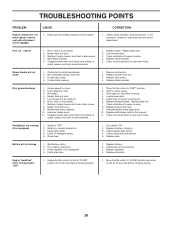
... under mower. 4. Clean battery terminals. 6. Spark plug wire loose. 11. Bent blade mandrel. 3. Replace damaged parts. 25 Faulty solenoid or starter. 9. Depress clutch/brake pedal. 2. Recharge or replace battery. 4. Engine clicks but will not turn over 1. Set in Service Adjustments section. 8. Dirty air filter. 6. Dirty engine air screen/fins. 12. Check oil level/change spark plug. 7. Replace fuel filter. 8. Drain fuel tank and carburetor, refill tank with fresh gasoline and replace fuel filter. 8. See "To Adjust Carburetor" in...
... under mower. 4. Clean battery terminals. 6. Spark plug wire loose. 11. Bent blade mandrel. 3. Replace damaged parts. 25 Faulty solenoid or starter. 9. Depress clutch/brake pedal. 2. Recharge or replace battery. 4. Engine clicks but will not turn over 1. Set in Service Adjustments section. 8. Dirty air filter. 6. Dirty engine air screen/fins. 12. Check oil level/change spark plug. 7. Replace fuel filter. 8. Drain fuel tank and carburetor, refill tank with fresh gasoline and replace fuel filter. 8. See "To Adjust Carburetor" in...
User Manual
Page 26
...Engine throttle control not set at "SLOW" position for proper air pressure. 6. If not corrected, contact an authorized service center/ department. Buildup of grass, leaves and trash under mower. 4. Tighten blade bolt. 2. Mower drive belt worn. 9. Improper blades used. 11. Allow grass to slower speed. 3. Mower deck not level. 3. Replace blade. Poor grass discharge 1. Engine speed too slow. 2. Level mower deck. 5. Bad battery cell(s). 2. Replace battery. 2. Replace mower drive belt. 3. Replace blade mandrel. Switch is "OFF". 2. Check wiring...
...Engine throttle control not set at "SLOW" position for proper air pressure. 6. If not corrected, contact an authorized service center/ department. Buildup of grass, leaves and trash under mower. 4. Tighten blade bolt. 2. Mower drive belt worn. 9. Improper blades used. 11. Allow grass to slower speed. 3. Mower deck not level. 3. Replace blade. Poor grass discharge 1. Engine speed too slow. 2. Level mower deck. 5. Bad battery cell(s). 2. Replace battery. 2. Replace mower drive belt. 3. Replace blade mandrel. Switch is "OFF". 2. Check wiring...
User Manual
Page 37
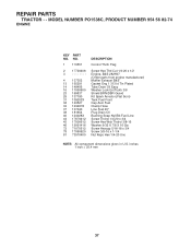
... DESCRIPTION Control Th/ch Flag Screw Hex Thd Cut 1/4-20 x 1/2 Engine, B&S 282H07 (Order parts from engine manufacturer) Muffler Exhaust B&S Gasket Eng 1 313 Id Tin Plated Tube Drain Oil Easy Washer Lock Ext Tooth 3/8 Shield BRN/DBR Guard Kit Spark Arrestor (Flat Scrn) Tank Fuel Front Cap Asm Fuel Clamp Hose Line Fuel 20" Plug Drain Oil Bushing Snap Nyl Blk Fuel Line Screw Thdrol 1/4-20 x 3/4 Screw Hex Wsh Thdrol 3/8-16 Washer 9/32 X 7/8 X 16 Ga Screw Hexcap...
... DESCRIPTION Control Th/ch Flag Screw Hex Thd Cut 1/4-20 x 1/2 Engine, B&S 282H07 (Order parts from engine manufacturer) Muffler Exhaust B&S Gasket Eng 1 313 Id Tin Plated Tube Drain Oil Easy Washer Lock Ext Tooth 3/8 Shield BRN/DBR Guard Kit Spark Arrestor (Flat Scrn) Tank Fuel Front Cap Asm Fuel Clamp Hose Line Fuel 20" Plug Drain Oil Bushing Snap Nyl Blk Fuel Line Screw Thdrol 1/4-20 x 3/4 Screw Hex Wsh Thdrol 3/8-16 Washer 9/32 X 7/8 X 16 Ga Screw Hexcap...
User Manual
Page 39
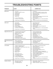
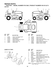
inches 1 inch = 25.4 mm 39 MODEL NUMBER PO1538C, PRODUCT NUMBER 954 56 82-74 DECALS 8 7 12 14 6 8 15 9 16 4 3 1 KEY PART NO. REPAIR PARTS TRACTOR - - Decal Fender 17 KEY PART NO. DESCRIPTION 1 59192 Cap, Tire valve 2 65139 Stem, Valve 3 106222X Tire, Front 4 59904 Tube, Front (Service item only) 5 106732X624 Rim assembly, 6"front 3,9 6 278H Fitting, Grease (Front wheel only) 7 9040H Bearing, Flange (Front wheel only) 11 8 106108X624 Rim assembly, 8" rear 9 124635X Tire...
inches 1 inch = 25.4 mm 39 MODEL NUMBER PO1538C, PRODUCT NUMBER 954 56 82-74 DECALS 8 7 12 14 6 8 15 9 16 4 3 1 KEY PART NO. REPAIR PARTS TRACTOR - - Decal Fender 17 KEY PART NO. DESCRIPTION 1 59192 Cap, Tire valve 2 65139 Stem, Valve 3 106222X Tire, Front 4 59904 Tube, Front (Service item only) 5 106732X624 Rim assembly, 6"front 3,9 6 278H Fitting, Grease (Front wheel only) 7 9040H Bearing, Flange (Front wheel only) 11 8 106108X624 Rim assembly, 8" rear 9 124635X Tire...
User Manual
Page 43
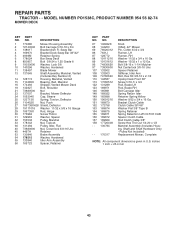
... Bolt, Hex Hd 3/8-16 x 2-1/2 Upstop Deck Front 38" Screw 5/16-1/ x 3/4 Rod, Brake LH Rod, Brake RH Bolt Carriage Idler Spring Return Idler Retainer Spring Yellow Washer 9/32 x 3/4 x 16 Ga. Bracket Clutch Cable Clutch Cable 38"/46" Washer Flat 3/8" Type B Spring Retainer Spring Retention LVR CLTCH CAB Spacer Clutch Cable Rod Clutch Cable 3/8" Screw Hex Thd Cut 1/4-20 x 1/2 Mandrel Assembly (Includes Housing, Shaft and Shaft Hardware Only - DESCRIPTION 1 170280 Mower Housing Assembly 2 72140506 Bolt Carriage 5/16-18 x 3/4 3 138017 Bracket Asm Fr. REPAIR PARTS TRACTOR...
... Bolt, Hex Hd 3/8-16 x 2-1/2 Upstop Deck Front 38" Screw 5/16-1/ x 3/4 Rod, Brake LH Rod, Brake RH Bolt Carriage Idler Spring Return Idler Retainer Spring Yellow Washer 9/32 x 3/4 x 16 Ga. Bracket Clutch Cable Clutch Cable 38"/46" Washer Flat 3/8" Type B Spring Retainer Spring Retention LVR CLTCH CAB Spacer Clutch Cable Rod Clutch Cable 3/8" Screw Hex Thd Cut 1/4-20 x 1/2 Mandrel Assembly (Includes Housing, Shaft and Shaft Hardware Only - DESCRIPTION 1 170280 Mower Housing Assembly 2 72140506 Bolt Carriage 5/16-18 x 3/4 3 138017 Bracket Asm Fr. REPAIR PARTS TRACTOR...


