

User Manual
Page 2
...approaching blind corners, shrubs, trees, or other people before removing grass catcher or unclogging chute. • Mow only in severe injury or death. The mower could be picked up . They are flammable and vapors are sharp and can cut. Never store the machine or fuel container inside a closed area. ...of other objects that you will remain where you strike an object. Use only an approved container. - IV. Allow machine to the presence of the mower discharge direction and do not mow it at anyone enters the area. • Never carry passengers. • Do not mow in . • ...
...approaching blind corners, shrubs, trees, or other people before removing grass catcher or unclogging chute. • Mow only in severe injury or death. The mower could be picked up . They are flammable and vapors are sharp and can cut. Never store the machine or fuel container inside a closed area. ...of other objects that you will remain where you strike an object. Use only an approved container. - IV. Allow machine to the presence of the mower discharge direction and do not mow it at anyone enters the area. • Never carry passengers. • Do not mow in . • ...

User Manual
Page 3
.... • Watch for holes, ruts, or bumps. Too heavy of your tractor. Always look behind before mowing. SAFETY RULES Safe Operation Practices for Ride-On Mowers • Be sure the area is dangerous. Stop machine if anyone enters the area. • Never carry passengers or children even with specifications of the...
.... • Watch for holes, ruts, or bumps. Too heavy of your tractor. Always look behind before mowing. SAFETY RULES Safe Operation Practices for Ride-On Mowers • Be sure the area is dangerous. Stop machine if anyone enters the area. • Never carry passengers or children even with specifications of the...

User Manual
Page 8
...instructions have been completed. • Check engine oil level and fill fuel tank with the instructions that are shown for replacing motion and mower blade drive belts in the Operation section of this manual. WHILE LEARNING HOW TO USE YOUR TRACTOR, PAY EXTRA ATTENTION TO THE FOLLOWING ...to stop tractor, set the parking brake. • Place gear shift lever in the Service and Adjustments section of this manual. See "TO LEVEL MOWER HOUSING" in neutral (N) position. • Press lift lever plunger and raise attachment lift lever to idle position. • Depress clutch/brake pedal...
...instructions have been completed. • Check engine oil level and fill fuel tank with the instructions that are shown for replacing motion and mower blade drive belts in the Operation section of this manual. WHILE LEARNING HOW TO USE YOUR TRACTOR, PAY EXTRA ATTENTION TO THE FOLLOWING ...to stop tractor, set the parking brake. • Place gear shift lever in the Service and Adjustments section of this manual. See "TO LEVEL MOWER HOUSING" in neutral (N) position. • Press lift lever plunger and raise attachment lift lever to idle position. • Depress clutch/brake pedal...

User Manual
Page 9
OPERATION These symbols may appear on your tractor or in literature supplied with the product. BATTERY CAUTION OR WARNING REVERSE FORWARD FAST SLOW ENGINE ON ENGINE OFF OIL PRESSURE LIGHTS ON OVER TEMP LIGHT FUEL CHOKE MOWER HEIGHT PARKING BRAKE LOCKED UNLOCKED MOWER LIFT ATTACHMENT REVERSE CLUTCH ENGAGED NEUTRAL HIGH P LOW PARKING BRAKE 15 15 15 IGNITION ATTACHMENT CLUTCH DISENGAGED KEEP AREA CLEAR SLOPE HAZARDS (SEE SAFETY RULES SECTION) DANGER, KEEP HANDS AND FEET AWAY 9 FREE WHEEL (Automatic Models only) Learn and understand their meaning.
OPERATION These symbols may appear on your tractor or in literature supplied with the product. BATTERY CAUTION OR WARNING REVERSE FORWARD FAST SLOW ENGINE ON ENGINE OFF OIL PRESSURE LIGHTS ON OVER TEMP LIGHT FUEL CHOKE MOWER HEIGHT PARKING BRAKE LOCKED UNLOCKED MOWER LIFT ATTACHMENT REVERSE CLUTCH ENGAGED NEUTRAL HIGH P LOW PARKING BRAKE 15 15 15 IGNITION ATTACHMENT CLUTCH DISENGAGED KEEP AREA CLEAR SLOPE HAZARDS (SEE SAFETY RULES SECTION) DANGER, KEEP HANDS AND FEET AWAY 9 FREE WHEEL (Automatic Models only) Learn and understand their meaning.

User Manual
Page 10
... THROTTLE/CHOKE CONTROL ATTACHMENT CLUTCH LEVER IGNITION SWITCH LIGHT SWITCH LIFT LEVER PLUNGER ATTACHMENT LIFT LEVER CLUTCH/BRAKE PEDAL GEARSHIFT LEVER MOWER DECK HEIGHT ADJUSTMENT POSITIONS PARKING BRAKE FIG. 4 Our tractors conform to the safety standards of tractor. Save this manual ...CONTROL: Used for declutching and braking the tractor and starting and controlling engine speed. ATTACHMENT CLUTCH LEVER: Used to engage the mower blades, or other attachments mounted to your tractor. GEARSHIFT LEVER: Selects the speed and direction of the American National Standards Institute....
... THROTTLE/CHOKE CONTROL ATTACHMENT CLUTCH LEVER IGNITION SWITCH LIGHT SWITCH LIFT LEVER PLUNGER ATTACHMENT LIFT LEVER CLUTCH/BRAKE PEDAL GEARSHIFT LEVER MOWER DECK HEIGHT ADJUSTMENT POSITIONS PARKING BRAKE FIG. 4 Our tractors conform to the safety standards of tractor. Save this manual ...CONTROL: Used for declutching and braking the tractor and starting and controlling engine speed. ATTACHMENT CLUTCH LEVER: Used to engage the mower blades, or other attachments mounted to your tractor. GEARSHIFT LEVER: Selects the speed and direction of the American National Standards Institute....

User Manual
Page 11
... • Operating engine at less than full throttle reduces the battery charging rate. • Full throttle offers the best bagging and mower perfor- Always remove key when leaving tractor to prevent unauthorized use. • Never use choke to "DISENGAGED" position. to slow ...operator's position; CLUTCH/BRAKE PEDAL "DRIVE" POSITION PARKING BRAKE "DISENGAGED" POSITION FIG. 5 STOPPING (See Fig. 5) MOWER BLADES - • To stop mower blades,move throttle control to slow position and allowing engine to over spectacles or standard safety glasses. OPERATION The operation of...
... • Operating engine at less than full throttle reduces the battery charging rate. • Full throttle offers the best bagging and mower perfor- Always remove key when leaving tractor to prevent unauthorized use. • Never use choke to "DISENGAGED" position. to slow ...operator's position; CLUTCH/BRAKE PEDAL "DRIVE" POSITION PARKING BRAKE "DISENGAGED" POSITION FIG. 5 STOPPING (See Fig. 5) MOWER BLADES - • To stop mower blades,move throttle control to slow position and allowing engine to over spectacles or standard safety glasses. OPERATION The operation of...

User Manual
Page 12
...for opposite side installing gauge wheel in same adjustment hole. "ENGAGED" POSITION ATTACHMENT LIFT LEVER HIGH POSITION CAUTION: Do not operate the mower without either the entire grass catcher, on dipstick is reached. disengage attachment clutch control. GAUGE WHEEL MOUNTING BRACKET 3/8-16 LOCKNUT 3/8 WASHER ...manual). • To change engine oil, see the Customer Responsibilities section in this manual). • With mower in desired height of cut . • Start mower blades by the operator to leave the seat with specifications of the manufacturer of your tractor. Use an ...
...for opposite side installing gauge wheel in same adjustment hole. "ENGAGED" POSITION ATTACHMENT LIFT LEVER HIGH POSITION CAUTION: Do not operate the mower without either the entire grass catcher, on dipstick is reached. disengage attachment clutch control. GAUGE WHEEL MOUNTING BRACKET 3/8-16 LOCKNUT 3/8 WASHER ...manual). • To change engine oil, see the Customer Responsibilities section in this manual). • With mower in desired height of cut . • Start mower blades by the operator to leave the seat with specifications of the manufacturer of your tractor. Use an ...

User Manual
Page 13
...Storage Instructions for the first time or if the engine has run starter continuously for best engine performance. This may occur. See "TO LEVEL MOWER HOUSING" in the Service and Adjustments section of this manual. • The left hand turns until the fuel lines and carburetor are discharged ...of gas tank filler neck. WARM WEATHER STARTING (50° F and above 3000 feet) or in the opposite direction making left hand side of mower should be used for one or two rounds, mow in cold temperatures (below ) • When engine starts, allow it should be emptied before ...
...Storage Instructions for the first time or if the engine has run starter continuously for best engine performance. This may occur. See "TO LEVEL MOWER HOUSING" in the Service and Adjustments section of this manual. • The left hand turns until the fuel lines and carburetor are discharged ...of gas tank filler neck. WARM WEATHER STARTING (50° F and above 3000 feet) or in the opposite direction making left hand side of mower should be used for one or two rounds, mow in cold temperatures (below ) • When engine starts, allow it should be emptied before ...

User Manual
Page 14
.... • Check brake operation. • Check tire pressure. • Check operator presence and interlock systems for proper operation. • Check for Loose Fasteners A Sharpen/Replace Mower Blades C T Lubrication Chart 0 Check Battery Level R Clean Battery and Terminals Check Transaxle Cooling Adjust Blade Belt(s) Tension Adjust Motion Drive Belt(s) Tension Check Engine Oil...
.... • Check brake operation. • Check tire pressure. • Check operator presence and interlock systems for proper operation. • Check for Loose Fasteners A Sharpen/Replace Mower Blades C T Lubrication Chart 0 Check Battery Level R Clean Battery and Terminals Check Transaxle Cooling Adjust Blade Belt(s) Tension Adjust Motion Drive Belt(s) Tension Check Engine Oil...

User Manual
Page 15
...downward, sharpen the heavy end until the blade is balanced. If your local parts dealer. BLADE REMOVAL (See Fig. 9) • Raise mower to highest position to allow access to an unthreaded portion of the center hole may cause tire damage. OPERATOR PRESENCE SYSTEM Be sure operator ...presence and interlock systems are not. • Slide blade on the mower. • To check blade balance, you do not recommend sharpening blade - Do not attempt to sharpen while on to blades. • Remove...
...downward, sharpen the heavy end until the blade is balanced. If your local parts dealer. BLADE REMOVAL (See Fig. 9) • Raise mower to highest position to allow access to an unthreaded portion of the center hole may cause tire damage. OPERATOR PRESENCE SYSTEM Be sure operator ...presence and interlock systems are not. • Slide blade on the mower. • To check blade balance, you do not recommend sharpening blade - Do not attempt to sharpen while on to blades. • Remove...

User Manual
Page 19
... by re- moving parts have completely stopped. • Disconnect spark plug wire from under tractor with plug. IMPORTANT: IF AN ATTACHMENT OTHER THAN THE MOWER DECK IS TO BE MOUNTED ON THE TRACTOR, REMOVE THE FRONT LINKS AND HOOK THE CLUTCH SPRING INTO SQUARE HOLE IN FRAME. TRACTOR TO REMOVE... MOWER (See Fig. 16) Mower will be easier to remove from the right side of tractor. • Place attachment clutch in reverse order of bracket. • Disconnect...
... by re- moving parts have completely stopped. • Disconnect spark plug wire from under tractor with plug. IMPORTANT: IF AN ATTACHMENT OTHER THAN THE MOWER DECK IS TO BE MOUNTED ON THE TRACTOR, REMOVE THE FRONT LINKS AND HOOK THE CLUTCH SPRING INTO SQUARE HOLE IN FRAME. TRACTOR TO REMOVE... MOWER (See Fig. 16) Mower will be easier to remove from the right side of tractor. • Place attachment clutch in reverse order of bracket. • Disconnect...
User Manual
Page 20
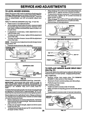
... position. MANDREL "D" "D" FIG. 19 BOTH FRONT LINKS MUST BE EQUAL IN LENGTH NUT "F" TRUNNION FRONT LINKS NUT "E" SUSPENSION ARM FIG. 20 TO REPLACE MOWER BLADE DRIVE BELT (See Fig. 21) LIFT LINK ADJUSTMENT NUT FIG. 18 FRONT-TO-BACK ADJUSTMENT (See Figs. 19 and 20) IMPORTANT: DECK MUST BE... Install new belt in reverse order of removal. • Make sure belt is in reverse order of adjustment nut will not properly adjust your mower. The mower blade drive belt may be adjusted so that side. • To lower one side of turns. 20 MANDREL PULLEY MANDREL PULLEY IDLER PULLEYS FIG...
... position. MANDREL "D" "D" FIG. 19 BOTH FRONT LINKS MUST BE EQUAL IN LENGTH NUT "F" TRUNNION FRONT LINKS NUT "E" SUSPENSION ARM FIG. 20 TO REPLACE MOWER BLADE DRIVE BELT (See Fig. 21) LIFT LINK ADJUSTMENT NUT FIG. 18 FRONT-TO-BACK ADJUSTMENT (See Figs. 19 and 20) IMPORTANT: DECK MUST BE... Install new belt in reverse order of removal. • Make sure belt is in reverse order of adjustment nut will not properly adjust your mower. The mower blade drive belt may be adjusted so that side. • To lower one side of turns. 20 MANDREL PULLEY MANDREL PULLEY IDLER PULLEYS FIG...

User Manual
Page 21
.... WITH PARKING BRAKE "ENGAGED" 1-1/2" NUT "A" JAM NUT TO ADJUST STEERING WHEEL ALIGNMENT If steering wheel crossbars are not horizontal (left footrest. • Remove mower (See "TO REMOVE MOWER" in this section of each battery, taking care not to short against nut "A". • Road test tractor for emergency starting, follow this procedure: IMPORTANT...
.... WITH PARKING BRAKE "ENGAGED" 1-1/2" NUT "A" JAM NUT TO ADJUST STEERING WHEEL ALIGNMENT If steering wheel crossbars are not horizontal (left footrest. • Remove mower (See "TO REMOVE MOWER" in this section of each battery, taking care not to short against nut "A". • Road test tractor for emergency starting, follow this procedure: IMPORTANT...

User Manual
Page 24
.... Do not use engine or carburetor cleaner products in the fuel tank or permanent damage may reach an open flame or spark. When mower is an acceptable alternative in minimizing the formation of fuel gum deposits during long periods of storage, battery cables should be used for 30... carburetor if using fuel stabilizer. Plastic cannot breathe which allows condensation to form and will cause your tractor to reach the carburetor. TRACTOR Remove mower from one ounce of this manual. • Be sure that does not retain moisture. NOTE: Fuel stabilizer is to rust. ENGINE OIL ...
.... Do not use engine or carburetor cleaner products in the fuel tank or permanent damage may reach an open flame or spark. When mower is an acceptable alternative in minimizing the formation of fuel gum deposits during long periods of storage, battery cables should be used for 30... carburetor if using fuel stabilizer. Plastic cannot breathe which allows condensation to form and will cause your tractor to reach the carburetor. TRACTOR Remove mower from one ounce of this manual. • Be sure that does not retain moisture. NOTE: Fuel stabilizer is to rust. ENGINE OIL ...

User Manual
Page 25
... depressed. 2. Faulty operator presence switch(es). 1. Disengage attachment clutch. 3. Contact an authorized service center/department. Loose or damaged wiring. 4. Check all wiring. 4. Build-up of mower housing. 4. Clean underside of grass, leaves and trash under...
... depressed. 2. Faulty operator presence switch(es). 1. Disengage attachment clutch. 3. Contact an authorized service center/department. Loose or damaged wiring. 4. Check all wiring. 4. Build-up of mower housing. 4. Clean underside of grass, leaves and trash under...

User Manual
Page 26
... too slow. 2. Place throttle control in clutch mechanism. 2. Shift to dry before mowing. 4. Clean underside of grass, leaves, and trash under mower. 8. Clean around mandrels to open vent holes. Headlight(s) not working (if so equipped) 1. Bulb(s) burned out. 3. Replace battery. 2. Check...Engine throttle control not set at "SLOW" position for 30 seconds before stopping engine. 26 Faulty operator-safety presence control system. 1. Mower deck not level. 3. Frozen blade mandrel. 1. Replace blade mandrel. Worn, bent or loose blade. 7. Check tires for 30 ...
... too slow. 2. Place throttle control in clutch mechanism. 2. Shift to dry before mowing. 4. Clean underside of grass, leaves, and trash under mower. 8. Clean around mandrels to open vent holes. Headlight(s) not working (if so equipped) 1. Bulb(s) burned out. 3. Replace battery. 2. Check...Engine throttle control not set at "SLOW" position for 30 seconds before stopping engine. 26 Faulty operator-safety presence control system. 1. Mower deck not level. 3. Frozen blade mandrel. 1. Replace blade mandrel. Worn, bent or loose blade. 7. Check tires for 30 ...
User Manual
Page 31
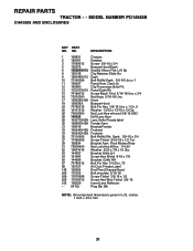
... 140273X599 Lens Grille Private label 30 169465X428 Fender Asm 31 136619 Bracket Fender 33 145244X428 Footrest 34 145243X428 Footrest 35 72110606 Bolt RdHd Sht. Pivot Mower Rear 51 73800400 Nut Lock Hex W/Ins. 1/4-20 52 19091416 Washer 9/32 x 7/8 x 16 Ga. 53 144697 Bracket Grille LH 54 161464 Screw Hex Wshd 8-18... Screw Hex Wsh Thdrol 3/8-16 212 156229 Insert Lens Reflector - - 5479J Plug Btn Blk NOTE: All component dimensions given in U.S. REPAIR PARTS TRACTOR - - MODEL NUMBER PO14542B CHASSIS AND ENCLOSURES KEY PART NO.
... 140273X599 Lens Grille Private label 30 169465X428 Fender Asm 31 136619 Bracket Fender 33 145244X428 Footrest 34 145243X428 Footrest 35 72110606 Bolt RdHd Sht. Pivot Mower Rear 51 73800400 Nut Lock Hex W/Ins. 1/4-20 52 19091416 Washer 9/32 x 7/8 x 16 Ga. 53 144697 Bracket Grille LH 54 161464 Screw Hex Wshd 8-18... Screw Hex Wsh Thdrol 3/8-16 212 156229 Insert Lens Reflector - - 5479J Plug Btn Blk NOTE: All component dimensions given in U.S. REPAIR PARTS TRACTOR - - MODEL NUMBER PO14542B CHASSIS AND ENCLOSURES KEY PART NO.
User Manual
Page 33
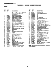
... 3/8-16x3/4 Cover Pedal Blk Round Pulley Engine Bolt, Hex 7/16-20 x 4 Grade 5 Washer, Lock, Hvy Hlcl Spring 7/16 Keeper Belt Engine Flproof Guide Belt Dr Mower Rh Washer 13/32 X 1-1/4 X 12 Ga Spacer Axle Washer 25/32 X 1 1/4 X 16 Ga E Ring Key Square 2 0 X 1845/ 1865 Washer 25/32 X 1 5/8 X 16ga Key Woodruff ... Unc x 2-3/4 Spacer Split 395 X 59 Bzp Keeper Belt Idler Washer 13/32 X 13/16 X 12 Ga Pulley Idler V Groove Plastic KEY PART NO. MODEL NUMBER PO14542B DRIVE KEY PART NO. NO. 48 154407 49 123205X 50 74760624 51 73680600 52 73680500 53 105710X 55 105709X 56 74760620 57 130801 59 169691...
... 3/8-16x3/4 Cover Pedal Blk Round Pulley Engine Bolt, Hex 7/16-20 x 4 Grade 5 Washer, Lock, Hvy Hlcl Spring 7/16 Keeper Belt Engine Flproof Guide Belt Dr Mower Rh Washer 13/32 X 1-1/4 X 12 Ga Spacer Axle Washer 25/32 X 1 1/4 X 16 Ga E Ring Key Square 2 0 X 1845/ 1865 Washer 25/32 X 1 5/8 X 16ga Key Woodruff ... Unc x 2-3/4 Spacer Split 395 X 59 Bzp Keeper Belt Idler Washer 13/32 X 13/16 X 12 Ga Pulley Idler V Groove Plastic KEY PART NO. MODEL NUMBER PO14542B DRIVE KEY PART NO. NO. 48 154407 49 123205X 50 74760624 51 73680600 52 73680500 53 105710X 55 105709X 56 74760620 57 130801 59 169691...
User Manual
Page 41
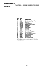
REPAIR PARTS TRACTOR - - MODEL NUMBER PO14542B MOWER LIFT KEY PART NO. NO. 1 159460 2 159471 3 105767X 4 12000002 5 19211621 6 120183X 7 109413X 8 124526X 11 139865 12 139866 13 4939M 15 173288 16 73350800 17 130171 ...
REPAIR PARTS TRACTOR - - MODEL NUMBER PO14542B MOWER LIFT KEY PART NO. NO. 1 159460 2 159471 3 105767X 4 12000002 5 19211621 6 120183X 7 109413X 8 124526X 11 139865 12 139866 13 4939M 15 173288 16 73350800 17 130171 ...
User Manual
Page 43
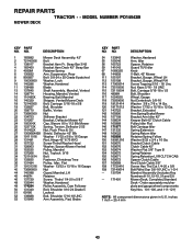
...Blade 13 137645 Shaft Assembly, Mandrel, Vented 14 128774 Housing, Mandrel, Vented 15 110485X Bearing, Ball, Mandrel 16 140329 Stripper, Vented Mower Deck 18 72140505 Bolt, Carriage 5/16-18 x 5/8 19 132827 Bolt, Shoulder 20 159770 Baffle, Vortex 21 73680500 Nut 22 134753 Stiffener...Nut Centerlock 3/8-16 Washer 3/8 x 7/8 x 14 Ga. Washer 17/32 x 15/16 x 12 Ga. inches 1 inch = 25.4 mm 43 MODEL NUMBER PO14542B MOWER DECK KEY PART NO. REPAIR PARTS TRACTOR - - NO. Bracket Clutch Cable Clutch Cable 42" Washer Flat 3/8" Type B Spring Retainer Spring Retention LVR CLTCH CAB ...
...Blade 13 137645 Shaft Assembly, Mandrel, Vented 14 128774 Housing, Mandrel, Vented 15 110485X Bearing, Ball, Mandrel 16 140329 Stripper, Vented Mower Deck 18 72140505 Bolt, Carriage 5/16-18 x 5/8 19 132827 Bolt, Shoulder 20 159770 Baffle, Vortex 21 73680500 Nut 22 134753 Stiffener...Nut Centerlock 3/8-16 Washer 3/8 x 7/8 x 14 Ga. Washer 17/32 x 15/16 x 12 Ga. inches 1 inch = 25.4 mm 43 MODEL NUMBER PO14542B MOWER DECK KEY PART NO. REPAIR PARTS TRACTOR - - NO. Bracket Clutch Cable Clutch Cable 42" Washer Flat 3/8" Type B Spring Retainer Spring Retention LVR CLTCH CAB ...


