
User Manual
Page 2
... operate the tiller without proper guards, plates, or other bolts at high speeds on slippery surfaces. • Handle fuel with electric drive motors or electric starting the engine (motor). • Do not operate the equipment without wearing adequate outer garments. Never fill fuel tank indoors. • Replace gasoline cap securely and clean up , transporting, adjusting or making repairs. Look behind and use of trouble. • Stop the engine (motor) when leaving the operating position. • Take all clutches and...
... operate the tiller without proper guards, plates, or other bolts at high speeds on slippery surfaces. • Handle fuel with electric drive motors or electric starting the engine (motor). • Do not operate the equipment without wearing adequate outer garments. Never fill fuel tank indoors. • Replace gasoline cap securely and clean up , transporting, adjusting or making repairs. Look behind and use of trouble. • Stop the engine (motor) when leaving the operating position. • Take all clutches and...
User Manual
Page 3
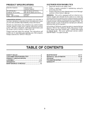
... MAINTENANCE 12-14 SERVICE & ADJUSTMENTS 15-18 STORAGE 19 TROUBLESHOOTING 20 WARRANTY 21 3 Should you experience any unimproved forest-covered, brush-covered or grass covered land unless the engine's exhaust system is required by the operator. Always observe the "SAFETY RULES". The instructions will enable you to service or repair this manual. Please read and retain this unit. PRODUCT SPECIFICATIONS Gasolina Capacity: Oil (API-SG-SL): (Capacity: 20 oz./0.6L) Spark Plug : (Gap...
... MAINTENANCE 12-14 SERVICE & ADJUSTMENTS 15-18 STORAGE 19 TROUBLESHOOTING 20 WARRANTY 21 3 Should you experience any unimproved forest-covered, brush-covered or grass covered land unless the engine's exhaust system is required by the operator. Always observe the "SAFETY RULES". The instructions will enable you to service or repair this manual. Please read and retain this unit. PRODUCT SPECIFICATIONS Gasolina Capacity: Oil (API-SG-SL): (Capacity: 20 oz./0.6L) Spark Plug : (Gap...

User Manual
Page 4
.../32 x 1 x 11 Gauge (1) Handle Lock Lever (1) Hairpin Clip (1) Pivot Bolt 3/8-16 UNC Grade 5 Extra Shear Pins & Clips 4 Use the correct tools as necessary to insure proper tightness. To ensure safe and proper operation of your tiller all parts and hardware you are listed. (1) Utility knife (1) Tire pressure gauge (1) Pair of those parts left hand is mentioned in the operating position (standing behind tiller handles). ASSEMBLY Your new tiller has been assembled at the factory...
.../32 x 1 x 11 Gauge (1) Handle Lock Lever (1) Hairpin Clip (1) Pivot Bolt 3/8-16 UNC Grade 5 Extra Shear Pins & Clips 4 Use the correct tools as necessary to insure proper tightness. To ensure safe and proper operation of your tiller all parts and hardware you are listed. (1) Utility knife (1) Tire pressure gauge (1) Pair of those parts left hand is mentioned in the operating position (standing behind tiller handles). ASSEMBLY Your new tiller has been assembled at the factory...

User Manual
Page 5
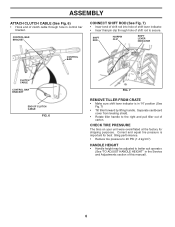
... easier adjustment. • Place flat . • Lower the handle assembly. IMPORTANT:WHEN UNPACKING AND ASSEMBLINGTILLER, BE CAREFUL NOT TO STRETCH OR KINK CABLES. • While holding handle assembly, cut cable ties securing handle assembly to remove tiller from handle assembly. SIDE OF TILLER HANDLE ASSEMBLY GEARCASE NOTCH HANDLE LOCK • Grasp handle assembly. HANDLE ASSEMBLY "UP" POSITION TIGHTEN HANDLE LOCK LEVER TO HOLD LOOSEN HANDLE LOCK LEVER TO MOVE FIG. 4 • Rotate handle assembly down.Insert rear carriage bolt first, with bolt head...
... easier adjustment. • Place flat . • Lower the handle assembly. IMPORTANT:WHEN UNPACKING AND ASSEMBLINGTILLER, BE CAREFUL NOT TO STRETCH OR KINK CABLES. • While holding handle assembly, cut cable ties securing handle assembly to remove tiller from handle assembly. SIDE OF TILLER HANDLE ASSEMBLY GEARCASE NOTCH HANDLE LOCK • Grasp handle assembly. HANDLE ASSEMBLY "UP" POSITION TIGHTEN HANDLE LOCK LEVER TO HOLD LOOSEN HANDLE LOCK LEVER TO MOVE FIG. 4 • Rotate handle assembly down.Insert rear carriage bolt first, with bolt head...
User Manual
Page 6
... be adjusted to the right and pull tiller out of this manual). 6 Separate cardboard cover from leveling shield. • Rotate tiller handle to better suit operator. (See "TO ADJUST HANDLE HEIGHT" in the Service and Adjustments section of carton. SHIFT ROD HAIRPIN CLIP SHIFT LEVER INDICATOR CONTROL BAR CLUTCH CABLE CONTROL BAR BRACKET END OF CLUTCH CABLE FIG. 6 FIG. 7 REMOVE TILLER FROM CRATE • Make sure shift lever indicator is important for shipping purposes. ASSEMBLY ATTACH CLUTCH CABLE (See...
... be adjusted to the right and pull tiller out of this manual). 6 Separate cardboard cover from leveling shield. • Rotate tiller handle to better suit operator. (See "TO ADJUST HANDLE HEIGHT" in the Service and Adjustments section of carton. SHIFT ROD HAIRPIN CLIP SHIFT LEVER INDICATOR CONTROL BAR CLUTCH CABLE CONTROL BAR BRACKET END OF CLUTCH CABLE FIG. 6 FIG. 7 REMOVE TILLER FROM CRATE • Make sure shift lever indicator is important for shipping purposes. ASSEMBLY ATTACH CLUTCH CABLE (See...

User Manual
Page 7
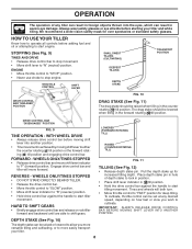
.... Used when starting a cold engine. Used to start the engine. Adjustable to shift transmission gears. Shows which tiller will dig. DEPTH STAKE - DRAG STAKE - Used to protect small plants from being buried. Save this manual for future reference. S CAUTION ENGINE ENGINE FAST SLOW CHOKE FUEL OIL TILLING TILLING FORWARD NEUTRAL REVERSE OR WARNING ON OFF THROTTLE CONTROL SHIFT LEVER DRIVE CONTROL BAR DRAG STAKE CHOKE CONTROL SHIFT LEVER INDICATOR DEPTH STAKE LEVELING SHIELD OUTER SIDE SHIELD RECOIL STARTER HANDLE...
.... Used when starting a cold engine. Used to start the engine. Adjustable to shift transmission gears. Shows which tiller will dig. DEPTH STAKE - DRAG STAKE - Used to protect small plants from being buried. Save this manual for future reference. S CAUTION ENGINE ENGINE FAST SLOW CHOKE FUEL OIL TILLING TILLING FORWARD NEUTRAL REVERSE OR WARNING ON OFF THROTTLE CONTROL SHIFT LEVER DRIVE CONTROL BAR DRAG STAKE CHOKE CONTROL SHIFT LEVER INDICATOR DEPTH STAKE LEVELING SHIELD OUTER SIDE SHIELD RECOIL STARTER HANDLE...
User Manual
Page 8
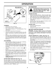
OPERATION The operation of depth stake to lock in position. • Place shift lever indicator in ( )till position. • Hold the drive control bar against the handle to "FAST" position for deep tilling. Always wear safety glasses or eye shields before adding fuel and oil or attempting to start tiller movement. ENGINE • Move throttle control to "STOP" position. • Never use choke to "F" (forward) position. THROTTLE CONTROL SHIFT LEVER SHALLOWEST TILLING (CULTIVATING) DEEPEST TILLING DEPTH...
OPERATION The operation of depth stake to lock in position. • Place shift lever indicator in ( )till position. • Hold the drive control bar against the handle to "FAST" position for deep tilling. Always wear safety glasses or eye shields before adding fuel and oil or attempting to start tiller movement. ENGINE • Move throttle control to "STOP" position. • Never use choke to "F" (forward) position. THROTTLE CONTROL SHIFT LEVER SHALLOWEST TILLING (CULTIVATING) DEEPEST TILLING DEPTH...
User Manual
Page 9
... transporting, allow tiller engine and muffler to desired speed. Tines will not turn . • Move throttle control "FAST" position for easier starting (See oil viscosity chart in slot and nut "B". All oil must meet A.P.I. Disconnect spark plug wire. Place depth stake pin in "F" (forward) position. Service Classification SG-SL. • Reinstall engine oil cap and tighten. • For cold weather operation you wish to lock in position. • Place...
... transporting, allow tiller engine and muffler to desired speed. Tines will not turn . • Move throttle control "FAST" position for easier starting (See oil viscosity chart in slot and nut "B". All oil must meet A.P.I. Disconnect spark plug wire. Place depth stake pin in "F" (forward) position. Service Classification SG-SL. • Reinstall engine oil cap and tighten. • For cold weather operation you wish to lock in position. • Place...
User Manual
Page 10
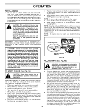
... tiller. NOTE: A warm engine requires less choking to start of compression cycle (rope will take extra pulls of leaded gasoline will increase carbon and lead oxide deposits and reduce valve life). Use fresh fuel next season. TO START ENGINE (See Fig. 14) • CAUTION: Keep drive control bar in cold temperatures (below 32°F), the carburetor fuel mixture may be adjusted for best engine performance. Pull rope out slowly until the fuel lines and carburetor...
... tiller. NOTE: A warm engine requires less choking to start of compression cycle (rope will take extra pulls of leaded gasoline will increase carbon and lead oxide deposits and reduce valve life). Use fresh fuel next season. TO START ENGINE (See Fig. 14) • CAUTION: Keep drive control bar in cold temperatures (below 32°F), the carburetor fuel mixture may be adjusted for best engine performance. Pull rope out slowly until the fuel lines and carburetor...

User Manual
Page 11
... sod or hard ground, apply upward pressure on handle or lower the depth stake. 4 3 2 1 5 6 7 ADJUST WHEELS FOR CULTIVATING (See Figs. 17 and 18) • Place blocks under right hand side of wheel and remove blocks. • Repeat preceding steps on inside of tiller and remove hairpin clip and clevis pin from the plants. OPERATION • Do not lean on the...
... sod or hard ground, apply upward pressure on handle or lower the depth stake. 4 3 2 1 5 6 7 ADJUST WHEELS FOR CULTIVATING (See Figs. 17 and 18) • Place blocks under right hand side of wheel and remove blocks. • Repeat preceding steps on inside of tiller and remove hairpin clip and clevis pin from the plants. OPERATION • Do not lean on the...
User Manual
Page 12
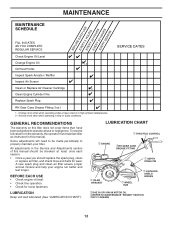
... operator abuse or negligence. BEFORE EACH USE • Check engine oil level. • Check tine operation. • Check for wear. GENERAL RECOMMENDATIONS The warranty on this tiller does not cover items that have been subjected to properly maintain your engine run better and last longer. A new spark plug and clean air filter assure proper air-fuel mixture and help your tiller. All adjustments in this manual should replace the spark plug, clean or replace air filter, and check tines and belts...
... operator abuse or negligence. BEFORE EACH USE • Check engine oil level. • Check tine operation. • Check for wear. GENERAL RECOMMENDATIONS The warranty on this tiller does not cover items that have been subjected to properly maintain your engine run better and last longer. A new spark plug and clean air filter assure proper air-fuel mixture and help your tiller. All adjustments in this manual should replace the spark plug, clean or replace air filter, and check tines and belts...
User Manual
Page 13
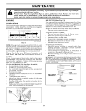
.... COVER KNOB COVER AIR CLEANER CARTRIDGE FOAM PRECLEANER BASE FIG. 21 OIL DRAIN PLUG OIL FILLER OIL LEVEL PLUG FIG. 20 13 MAINTENANCE Disconnect spark plug wire before tipping unit for 25 hours in one year. Keep the engine free of plug use . Clean base carefully to prevent debris from running low on flat least once a year if the tiller is on tiller, and catch oil in a suitable container. • Remove drain plug. • For easier removal...
.... COVER KNOB COVER AIR CLEANER CARTRIDGE FOAM PRECLEANER BASE FIG. 21 OIL DRAIN PLUG OIL FILLER OIL LEVEL PLUG FIG. 20 13 MAINTENANCE Disconnect spark plug wire before tipping unit for 25 hours in one year. Keep the engine free of plug use . Clean base carefully to prevent debris from running low on flat least once a year if the tiller is on tiller, and catch oil in a suitable container. • Remove drain plug. • For easier removal...
User Manual
Page 14
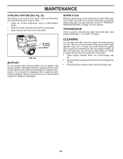
... and carburetor are hot. For proper engine performance and long life keep water out. Do not tamper with a spark arrester screen assembly, remove every 50 hours for cleaning and inspection. SPARK PLUG Replace spark plugs at the beginning of each tilling season or after every 50 hours of this manual. Spark plug type and gap setting is air cooled. CLEANING Do not clean your tiller when the engine and transmission are covered to clean your engine is...
... and carburetor are hot. For proper engine performance and long life keep water out. Do not tamper with a spark arrester screen assembly, remove every 50 hours for cleaning and inspection. SPARK PLUG Replace spark plugs at the beginning of each tilling season or after every 50 hours of this manual. Spark plug type and gap setting is air cooled. CLEANING Do not clean your tiller when the engine and transmission are covered to clean your engine is...
User Manual
Page 15
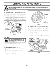
..., tiller will be positioned at different settings between "HIGH" and "LOW" positions. • Retighten handle lock lever securely after adjusting. TO REMOVE WHEEL (See Fig. 24) • Place blocks under transmission to one side. • Keep tires free of belt guard (located behind wheel). • Pull belt guard out and away from wheel. • Remove wheel and tire. • Repair tire and reassemble. Pull wheel out from tiller about 1 inch. • Remove two (2) screws from side of belt guard. • Remove hex nut and...
..., tiller will be positioned at different settings between "HIGH" and "LOW" positions. • Retighten handle lock lever securely after adjusting. TO REMOVE WHEEL (See Fig. 24) • Place blocks under transmission to one side. • Keep tires free of belt guard (located behind wheel). • Pull belt guard out and away from wheel. • Remove wheel and tire. • Repair tire and reassemble. Pull wheel out from tiller about 1 inch. • Remove two (2) screws from side of belt guard. • Remove hex nut and...

User Manual
Page 16
... about 5/8 inch (16 mm) stretch when drive control bar is engaged. • Tighten cable clip screw securely. NOTE POSITION OF BELT TO GUIDES. • Check belt adjustment as described in "TO REMOVE BELT GUARD". • Remove old belt by slipping off engine pulley first then remove from transmission pulley. • Place new belt in "ENGAGED" position. SERVICE AND ADJUSTMENTS TO REPLACE GROUND DRIVE BELT (See Figs. 25 and 26) • Remove belt guard as described below. • Replace belt guard. • Reposition wheel and replace clevis pin and...
... about 5/8 inch (16 mm) stretch when drive control bar is engaged. • Tighten cable clip screw securely. NOTE POSITION OF BELT TO GUIDES. • Check belt adjustment as described in "TO REMOVE BELT GUARD". • Remove old belt by slipping off engine pulley first then remove from transmission pulley. • Place new belt in "ENGAGED" position. SERVICE AND ADJUSTMENTS TO REPLACE GROUND DRIVE BELT (See Figs. 25 and 26) • Remove belt guard as described below. • Replace belt guard. • Reposition wheel and replace clevis pin and...
User Manual
Page 18
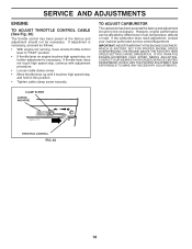
... AND WIRE engine_art_78 THROTTLE CONTROL FIG. 30 18 SERVICE AND ADJUSTMENTS ENGINE TO ADJUST THROTTLE CONTROL CABLE (See Fig. 30) The throttle control has been preset at the factory and adjustment should not be necessary. If adjustment is necessary, proceed as follows: • With engine not running, move remote throttle control lever to "FAST" position. • If throttle lever on engine touches high speed stop , and hold in fuel, temperature, altitude or load. If the carburetor does need adjustment...
... AND WIRE engine_art_78 THROTTLE CONTROL FIG. 30 18 SERVICE AND ADJUSTMENTS ENGINE TO ADJUST THROTTLE CONTROL CABLE (See Fig. 30) The throttle control has been preset at the factory and adjustment should not be necessary. If adjustment is necessary, proceed as follows: • With engine not running, move remote throttle control lever to "FAST" position. • If throttle lever on engine touches high speed stop , and hold in fuel, temperature, altitude or load. If the carburetor does need adjustment...
User Manual
Page 19
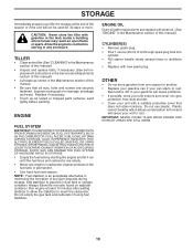
... run until the fuel lines and carburetor are securely fastened. ENGINE OIL Drain oil (with engine warm) and replace with gasoline in the Maintenance section of oil through spark plug hole into cylinder. • Pull starter handle slowly several times to distribute oil. • Replace with a suitable protective cover that all rusted or chipped paint surfaces; ACIDIC GAS CAN DAMAGE THE FUEL SYSTEM OF AN ENGINE WHILE IN STORAGE. • Empty the fuel tank by starting the engine...
... run until the fuel lines and carburetor are securely fastened. ENGINE OIL Drain oil (with engine warm) and replace with gasoline in the Maintenance section of oil through spark plug hole into cylinder. • Pull starter handle slowly several times to distribute oil. • Replace with a suitable protective cover that all rusted or chipped paint surfaces; ACIDIC GAS CAN DAMAGE THE FUEL SYSTEM OF AN ENGINE WHILE IN STORAGE. • Empty the fuel tank by starting the engine...
User Manual
Page 20
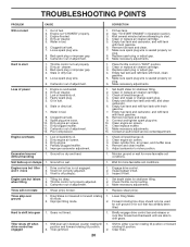
...Clean or replace air cleaner cartridge. 3. Clean and regap or change oil. 4. Empty and clean fuel tank and refill, and clean carburetor. 6. Clean engine air screen. 3. Tilling too deep. 2. Replace shear pin(s). Improper tilling mode. 1. Gears not timed. 1. Bad spark plug or improper gap. 9. Bad spark plug or improper gap. 4. Low oil level/dirty oil. 4. Set depth stake for shallower tilling. 2. Clean/replace muffler. 12. Drive control bar is seated properly on plug. 6. Inspect/adjust V-belt. 3. Engine runs but tiller won't move 1. Set...
...Clean or replace air cleaner cartridge. 3. Clean and regap or change oil. 4. Empty and clean fuel tank and refill, and clean carburetor. 6. Clean engine air screen. 3. Tilling too deep. 2. Replace shear pin(s). Improper tilling mode. 1. Gears not timed. 1. Bad spark plug or improper gap. 9. Bad spark plug or improper gap. 4. Low oil level/dirty oil. 4. Set depth stake for shallower tilling. 2. Clean/replace muffler. 12. Drive control bar is seated properly on plug. 6. Inspect/adjust V-belt. 3. Engine runs but tiller won't move 1. Set...
User Manual
Page 21
... to alteration, misuse, abuse, improper assembly or installation, delivery damage, or to the engine or components parts thereof. This is a limited Warranty within the meaning of how long an implied Warranty may last, so the above limitations or exclusions may have any power equipment unit or attachment are belts, tines, tine adapters, normal wear, normal adjustments, standard hardware and normal maintenance. 6.
... to alteration, misuse, abuse, improper assembly or installation, delivery damage, or to the engine or components parts thereof. This is a limited Warranty within the meaning of how long an implied Warranty may last, so the above limitations or exclusions may have any power equipment unit or attachment are belts, tines, tine adapters, normal wear, normal adjustments, standard hardware and normal maintenance. 6.

User Manual
Page 22
Model Number/Manufacturer's I.D. PARTS AND SERVICE This product has been expertly engineered and carefully manufactured to continually improve all of its authorized distributors and dealers; Number b. therefore, all mechanical products, some adjustments or part replacement may be directed to our website: www.poulan-pro.com/support.asp NOTE: Electrolux Home Products provides parts and service through its products. As with all requests for updated information and...
Model Number/Manufacturer's I.D. PARTS AND SERVICE This product has been expertly engineered and carefully manufactured to continually improve all of its authorized distributors and dealers; Number b. therefore, all mechanical products, some adjustments or part replacement may be directed to our website: www.poulan-pro.com/support.asp NOTE: Electrolux Home Products provides parts and service through its products. As with all requests for updated information and...


