
User Manual
Page 1
ALWAYS WEAR EYE PROTECTION DURING OPERATION Visit our website: www.poulan.com 404630 01.19.06 TR Printed in serious injury. Failure to do so can result in U.S.A. IMPORTANT MANUAL Do Not Throw Away 03076 OPERATOR'S MANUAL MODEL: C20H42YT LAWN TRACTOR WARNING: Read this Manual and follow all Warnings and Safety Instructions.
ALWAYS WEAR EYE PROTECTION DURING OPERATION Visit our website: www.poulan.com 404630 01.19.06 TR Printed in serious injury. Failure to do so can result in U.S.A. IMPORTANT MANUAL Do Not Throw Away 03076 OPERATOR'S MANUAL MODEL: C20H42YT LAWN TRACTOR WARNING: Read this Manual and follow all Warnings and Safety Instructions.

User Manual
Page 10
...FIG. 8 • Put attachment lift lever in place. JUST MOWER CUTTING HEIGHT" in this section of grass being mowed. • The average lawn should be assembled so they are approximate and may cause the cruise control to 4". J K L FIG. 7 SYSTEM CHARACTERISTICS The cruise control should... be mowed twice. FIG.9 TO OPERATE MOWER Your tractor is approximately 1" to disengage. OPERATION TO USE CRUISE CONTROL -J (See Fig. 7) The cruise control feature can be cut with attachment lift ...
...FIG. 8 • Put attachment lift lever in place. JUST MOWER CUTTING HEIGHT" in this section of grass being mowed. • The average lawn should be assembled so they are approximate and may cause the cruise control to 4". J K L FIG. 7 SYSTEM CHARACTERISTICS The cruise control should... be mowed twice. FIG.9 TO OPERATE MOWER Your tractor is approximately 1" to disengage. OPERATION TO USE CRUISE CONTROL -J (See Fig. 7) The cruise control feature can be cut with attachment lift ...
User Manual
Page 19
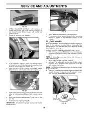
... the PSI shown on opposite side of clutch cable spring (Q) into hole in front mower bracket (H) and secure with retainer spring (K). • Hook end of tractor. E FIG. 21 • Raise attachment lift lever to lower mower F J H FIG. 20 • Push clutch cable housing guide (P) into bracket, ...in flated to the left side of this manual. Insert rod end of link assembly through front hole in tractor front suspension bracket (F). • Insert end of your lawn and lead you are properly in idler arm (R). • Install belt onto engine pulley (M). TO LEVEL MOWER ...
... the PSI shown on opposite side of clutch cable spring (Q) into hole in front mower bracket (H) and secure with retainer spring (K). • Hook end of tractor. E FIG. 21 • Raise attachment lift lever to lower mower F J H FIG. 20 • Push clutch cable housing guide (P) into bracket, ...in flated to the left side of this manual. Insert rod end of link assembly through front hole in tractor front suspension bracket (F). • Insert end of your lawn and lead you are properly in idler arm (R). • Install belt onto engine pulley (M). TO LEVEL MOWER ...


