
User Manual
Page 2
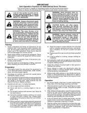
..., and other reproductive harm. WARNING: This snow thrower is spilled on the machine and in reverse. WARNING: Snow throwers have exposed rotating parts, which can get caught in order to operate the equipment. Keep the area of operation clear of all instructions on clothing, change clothing ... severe injury from contact, or from material thrown from foreign objects that will improve footing on sidewalks, driveways and other engine parts become extremely hot during operation or while performing an adjustment or repair to make any adjustments while the engine (motor) is not...
..., and other reproductive harm. WARNING: This snow thrower is spilled on the machine and in reverse. WARNING: Snow throwers have exposed rotating parts, which can get caught in order to operate the equipment. Keep the area of operation clear of all instructions on clothing, change clothing ... severe injury from contact, or from material thrown from foreign objects that will improve footing on sidewalks, driveways and other engine parts become extremely hot during operation or while performing an adjustment or repair to make any adjustments while the engine (motor) is not...
User Manual
Page 3
...this unit. When cleaning, repairing or inspecting the snow thrower, stop the engine and make certain the collector/impeller and all moving parts have competent, well-trained technicians and the proper tools to 50°F) SAE 5W-30 (below 32°F) Oil Capacity: 32...14-15 PRODUCT SPECIFICATIONS 3 SERVICE AND ADJUSTMENTS 16-18 CUSTOMER RESPONSIBILITIES 3 STORAGE 19 ASSEMBLY / PRE-OPERATION 5-7 TROUBLESHOOTING 20 OPERATION 8-13 REPAIR PARTS 22-39 MAINTENANCE SCHEDULE 14 3 WARRANTY BACK PAGE 6. To clear the chute: 1. Never store the machine with fuel in the fuel ...
...this unit. When cleaning, repairing or inspecting the snow thrower, stop the engine and make certain the collector/impeller and all moving parts have competent, well-trained technicians and the proper tools to 50°F) SAE 5W-30 (below 32°F) Oil Capacity: 32...14-15 PRODUCT SPECIFICATIONS 3 SERVICE AND ADJUSTMENTS 16-18 CUSTOMER RESPONSIBILITIES 3 STORAGE 19 ASSEMBLY / PRE-OPERATION 5-7 TROUBLESHOOTING 20 OPERATION 8-13 REPAIR PARTS 22-39 MAINTENANCE SCHEDULE 14 3 WARRANTY BACK PAGE 6. To clear the chute: 1. Never store the machine with fuel in the fuel ...
User Manual
Page 4
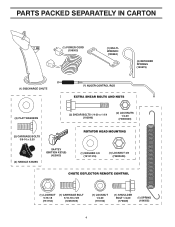
PARTS PACKED SEPARATELY IN CARTON (1) POWER CORD (198563) (1) MULTIWRENCH (180684) (3) RETAINER SPRINGS (169675) (2) FLAT WASHERS (2) SHEAR BOLTS 1/4-20 x 1-3/4 (192090) (2) LOCKNUTS 1/4-20 (73800400) (2) CARRIAGE BOLTS 3/8-16 x 2.25 (2) HANDLE KNOBS SAFTEY IGNITION KEY(S) (422663) (1) WASHER 3/8 (19131316) (1) LOCKNUT 3/8 (73800600) (1) LOCKNUT 5/16-18 (751153) (1) CARRIAGE BOLT 5/16-18 x 5/8 (72250505) (1) LOCKNUT 1/4-20 (191730) (1) SHOULDER BOLT 1/4-20 (179829) (1) SPRING (184505) 4
PARTS PACKED SEPARATELY IN CARTON (1) POWER CORD (198563) (1) MULTIWRENCH (180684) (3) RETAINER SPRINGS (169675) (2) FLAT WASHERS (2) SHEAR BOLTS 1/4-20 x 1-3/4 (192090) (2) LOCKNUTS 1/4-20 (73800400) (2) CARRIAGE BOLTS 3/8-16 x 2.25 (2) HANDLE KNOBS SAFTEY IGNITION KEY(S) (422663) (1) WASHER 3/8 (19131316) (1) LOCKNUT 3/8 (73800600) (1) LOCKNUT 5/16-18 (751153) (1) CARRIAGE BOLT 5/16-18 x 5/8 (72250505) (1) LOCKNUT 1/4-20 (191730) (1) SHOULDER BOLT 1/4-20 (179829) (1) SPRING (184505) 4
User Manual
Page 5
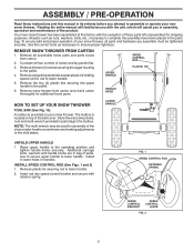
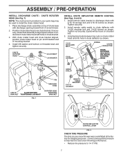
...HOW TO SET UP YOUR SNOW THROWER TOOL BOX (See Fig. 10) A toolbox is located on your snow thrower, all accessible loose parts and parts boxes from carton and check carton thoroughly for assembly of your snow thrower. Reading the entire manual will familiarize you with the unit, which... will assist you in assembly, operation and maintenance of parts. Install in lower holes in the toolbox. Remove all four corners of the belt cover. Remove the two (2) screws securing the auger housing...
...HOW TO SET UP YOUR SNOW THROWER TOOL BOX (See Fig. 10) A toolbox is located on your snow thrower, all accessible loose parts and parts boxes from carton and check carton thoroughly for assembly of your snow thrower. Reading the entire manual will familiarize you with the unit, which... will assist you in assembly, operation and maintenance of parts. Install in lower holes in the toolbox. Remove all four corners of the belt cover. Remove the two (2) screws securing the auger housing...

User Manual
Page 6
... lower handle. 2. Secure with retainer spring. With top end of rod positioned under right side of control panel, push down and insert top end of parts and retrieve the auger control rod from bag of rod into hole in auger control bracket. Hook spring in hole in the vinyl sleeve. Retrieve...
... lower handle. 2. Secure with retainer spring. With top end of rod positioned under right side of control panel, push down and insert top end of parts and retrieve the auger control rod from bag of rod into hole in auger control bracket. Hook spring in hole in the vinyl sleeve. Retrieve...
User Manual
Page 7
... on underside of chute rotater head with discharge opening toward front of snow thrower. 2. Tighten nut securely. Install spring hooks between hex nuts on your parts bag may be loose on top of mounting bracket. 4. Install 3/8 washer and locknut on pin and threaded stud of chute base with holes in chute...
... on underside of chute rotater head with discharge opening toward front of snow thrower. 2. Tighten nut securely. Install spring hooks between hex nuts on your parts bag may be loose on top of mounting bracket. 4. Install 3/8 washer and locknut on pin and threaded stud of chute base with holes in chute...
User Manual
Page 10
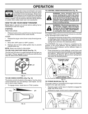
...from contact, or from material thrown from the discharge chute. TO CONTROL SNOW DISCHARGE (See Fig. 13) WARNING: Snow throwers have exposed rotating parts, which snow is to be thrown is controlled by the discharge chute control lever. • To change the discharge chute position, press downward on...warm engine. • To engage choke, rotate lever to stop throwing snow. HOW TO USE YOUR SNOW THROWER Know how to operate all moving parts to "FULL" position. Move lever back to throw snow a short distance; Always operate the snow thrower with the fuel shut-off valve is ...
...from contact, or from material thrown from the discharge chute. TO CONTROL SNOW DISCHARGE (See Fig. 13) WARNING: Snow throwers have exposed rotating parts, which snow is to be thrown is controlled by the discharge chute control lever. • To change the discharge chute position, press downward on...warm engine. • To engage choke, rotate lever to stop throwing snow. HOW TO USE YOUR SNOW THROWER Know how to operate all moving parts to "FULL" position. Move lever back to throw snow a short distance; Always operate the snow thrower with the fuel shut-off valve is ...

User Manual
Page 11
... to the snow thrower can result. • Slower speeds are for heavier snow and faster speeds are disengaged and the auger/impeller and all moving parts have stopped. CAUTION: Do not move lever to desired position BEFORE engaging the traction drive control lever. Damage to it 's mounting clip. squeeze right side...
... to the snow thrower can result. • Slower speeds are for heavier snow and faster speeds are disengaged and the auger/impeller and all moving parts have stopped. CAUTION: Do not move lever to desired position BEFORE engaging the traction drive control lever. Damage to it 's mounting clip. squeeze right side...
User Manual
Page 12
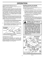
...oil or fuel. Do not store, spill or use extra caution and be picked up and thrown by loosening the 1/2" hex nuts, then moving parts to the edge of 30 days or longer. To avoid engine problems, the fuel system should be reversed, providing additional service before storage of ...highest position (lowest scraper clearance) to assure fuel freshness. BEFORE STARTING THE ENGINE CHECK ENGINE OIL LEVEL (See Fig. 19) The engine on your parts bag may be operated over gravel or rocky surfaces. Acidic gas can cause serious personal injury, property damage or damage to the snow thrower. &#...
...oil or fuel. Do not store, spill or use extra caution and be picked up and thrown by loosening the 1/2" hex nuts, then moving parts to the edge of 30 days or longer. To avoid engine problems, the fuel system should be reversed, providing additional service before storage of ...highest position (lowest scraper clearance) to assure fuel freshness. BEFORE STARTING THE ENGINE CHECK ENGINE OIL LEVEL (See Fig. 19) The engine on your parts bag may be operated over gravel or rocky surfaces. Acidic gas can cause serious personal injury, property damage or damage to the snow thrower. &#...
User Manual
Page 14
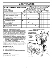
... to be sure they are functioning properly. BEFORE EACH USE 1. All adjustments in this unit. Check for wear. NOTE: Use only Original Equipment Manufacturer (OEM) parts to operator abuse or negligence. MAINTENANCE GENERAL RECOMMENDATIONS The warranty on this manual should be checked at least once each season. • Once a year, you...
... to be sure they are functioning properly. BEFORE EACH USE 1. All adjustments in this unit. Check for wear. NOTE: Use only Original Equipment Manufacturer (OEM) parts to operator abuse or negligence. MAINTENANCE GENERAL RECOMMENDATIONS The warranty on this manual should be checked at least once each season. • Once a year, you...
User Manual
Page 15
... thrower. Be careful not to allow dirt to slow leaks, tire sealant may be removed from snow thrower and engine. 6. Use gauge on your local parts dealer. Spark plug type and gap setting are covered to the oil drain plug and placement of this manual. NOTE: Although multi-viscosity oils (5W30...
... thrower. Be careful not to allow dirt to slow leaks, tire sealant may be removed from snow thrower and engine. 6. Use gauge on your local parts dealer. Spark plug type and gap setting are covered to the oil drain plug and placement of this manual. NOTE: Although multi-viscosity oils (5W30...
User Manual
Page 16
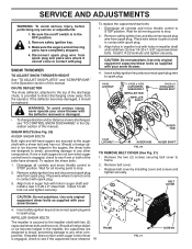
... manual. SHEAR BOLTS (See Fig. 20) AUGER SHEAR BOLTS Both right and left-hand augers are secured to stop . 2. Wait for all moving parts to the auger shaft with holes in impeller shaft and install two (2) new 1/4-20 x 1-5/8" capscrew/shear bolts. Place wire where it cannot come... two (2) capscrew/shear bolts and hex nuts. Remove safety ignition key. 3. Align hole in the OFF position. 2. Wait for all moving parts to any other components. Insert safety ignition key and reconnect spark plug wire to STOP position. Use only original equipment shear bolts as supplied with...
... manual. SHEAR BOLTS (See Fig. 20) AUGER SHEAR BOLTS Both right and left-hand augers are secured to stop . 2. Wait for all moving parts to the auger shaft with holes in impeller shaft and install two (2) new 1/4-20 x 1-5/8" capscrew/shear bolts. Place wire where it cannot come... two (2) capscrew/shear bolts and hex nuts. Remove safety ignition key. 3. Align hole in the OFF position. 2. Wait for all moving parts to any other components. Insert safety ignition key and reconnect spark plug wire to STOP position. Use only original equipment shear bolts as supplied with...
User Manual
Page 18
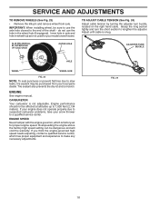
SERVICE AND ADJUSTMENTS TO REMOVE WHEELS (See Fig. 23) • Remove the klik pin and remove wheel from your local parts dealer. KLIK PIN (INSTALL IN OUTER HOLE OF AXLE ONLY) OUTER HOLE ADJUSTER TURN BUCKLE AXLE WHEEL WHEEL HUB FIG. 23 NOTE: To seal punctures ...
SERVICE AND ADJUSTMENTS TO REMOVE WHEELS (See Fig. 23) • Remove the klik pin and remove wheel from your local parts dealer. KLIK PIN (INSTALL IN OUTER HOLE OF AXLE ONLY) OUTER HOLE ADJUSTER TURN BUCKLE AXLE WHEEL WHEEL HUB FIG. 23 NOTE: To seal punctures ...
User Manual
Page 19
... entire snow thrower (See "CLEANING" in the tank inside a building where fumes may occur. • Use fresh fuel next season. Inspect moving parts for 30 days or more. ENGINE See engine manual. Replace with gasoline in the Maintenance section of this manual). 3. Do not use engine or ...spark plug. store it from dust and dirt. • Cover your snow thrower with clean engine oil. (See "ENGINE" in essential fuel system parts such as shown in storage. • Empty the fuel tank by starting the engine and letting it thoroughly, remove all dirt, grease, leaves, etc...
... entire snow thrower (See "CLEANING" in the tank inside a building where fumes may occur. • Use fresh fuel next season. Inspect moving parts for 30 days or more. ENGINE See engine manual. Replace with gasoline in the Maintenance section of this manual). 3. Do not use engine or ...spark plug. store it from dust and dirt. • Cover your snow thrower with clean engine oil. (See "ENGINE" in essential fuel system parts such as shown in storage. • Empty the fuel tank by starting the engine and letting it thoroughly, remove all dirt, grease, leaves, etc...
User Manual
Page 20
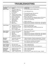
...muffler. 1. Stale fuel. 4. Move choke to ON position). 5. Empty fuel tank & carburetor, refill with fresh, clean gasoline. 4. Loose parts or damaged augers or impeller. 1. Drive belt is off valve to FULL position. 6. Friction drive wheel is flooded. 8. Contact an authorized.... 1. Water in OFF position. 6. Empty fuel tank & carburetor, refill with fresh, clean gasoline. Tighten all fasteners. Replace damaged parts. If vibration remains, contact an authorized service center/department. Loss of pulley. 2. Check / replace drive belt. Auger belt is disconnected...
...muffler. 1. Stale fuel. 4. Move choke to ON position). 5. Empty fuel tank & carburetor, refill with fresh, clean gasoline. 4. Loose parts or damaged augers or impeller. 1. Drive belt is off valve to FULL position. 6. Friction drive wheel is flooded. 8. Contact an authorized.... 1. Water in OFF position. 6. Empty fuel tank & carburetor, refill with fresh, clean gasoline. Tighten all fasteners. Replace damaged parts. If vibration remains, contact an authorized service center/department. Loss of pulley. 2. Check / replace drive belt. Auger belt is disconnected...
User Manual
Page 21
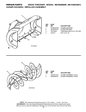
... be hazardous, damage your snow thrower and void your warranty. 21 REPAIR PARTS SNOW THROWER - inches. 1 inch = 25.4 mm IMPORTANT: Use only Original Equipment Manufacturer (O.E.M.) replacement parts. MODEL 961940009 (96194000901) AUGER HOUSING / IMPELLER ASSEMBLY 1 3 (5x) 4 (5x) 2 01.07.003-A KEY NO. 1 2 3 4 PART NO. 404930X428 404933X431 72270505 155377 DESCRIPTION AUGER HOUSING SCRAPPER BAR CARRIAGE BOLT...
... be hazardous, damage your snow thrower and void your warranty. 21 REPAIR PARTS SNOW THROWER - inches. 1 inch = 25.4 mm IMPORTANT: Use only Original Equipment Manufacturer (O.E.M.) replacement parts. MODEL 961940009 (96194000901) AUGER HOUSING / IMPELLER ASSEMBLY 1 3 (5x) 4 (5x) 2 01.07.003-A KEY NO. 1 2 3 4 PART NO. 404930X428 404933X431 72270505 155377 DESCRIPTION AUGER HOUSING SCRAPPER BAR CARRIAGE BOLT...
User Manual
Page 23
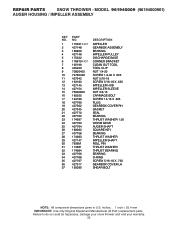
... THROWER - MODEL 961940009 (96194000901) AUGER HOUSING / IMPELLER ASSEMBLY KEY NO. 1 2 3 4 5 6 7 8 9 10 11 12 13 14 15 16 17 18 19 20 21 22 23 24 25 26 27 28 29 30 31 32 33 34 35 36 37 PART NO. 175321X431 427148 188909 427146 175322 178675X431 192199 405400 73800400 74780426 427942 163183... 5/16-18 X .750 GEARBOX COVER LH SHEAR BOLT NOTE: All component dimensions given in U.S. inches. 1 inch = 25.4 mm IMPORTANT: Use only Original Equipment Manufacturer (O.E.M.) replacement parts. Failure to do so could be hazardous, damage your snow thrower and void your warranty. 23
... THROWER - MODEL 961940009 (96194000901) AUGER HOUSING / IMPELLER ASSEMBLY KEY NO. 1 2 3 4 5 6 7 8 9 10 11 12 13 14 15 16 17 18 19 20 21 22 23 24 25 26 27 28 29 30 31 32 33 34 35 36 37 PART NO. 175321X431 427148 188909 427146 175322 178675X431 192199 405400 73800400 74780426 427942 163183... 5/16-18 X .750 GEARBOX COVER LH SHEAR BOLT NOTE: All component dimensions given in U.S. inches. 1 inch = 25.4 mm IMPORTANT: Use only Original Equipment Manufacturer (O.E.M.) replacement parts. Failure to do so could be hazardous, damage your snow thrower and void your warranty. 23
User Manual
Page 24
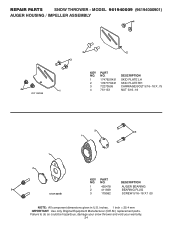
...CARRIAGE BOLT 5/16−18 X .75 1 4 751153 NUT 5/16−18 2 3 1 1 2 3 01.07.024-B KEY NO. 1 2 3 PART NO. 420478 411939 179582 DESCRIPTION AUGER BEARING BEARING PLUG SCREW 5/16−18 X 1.00 NOTE: All component dimensions given in U.S. inches. 1 inch = 25.4 mm... IMPORTANT: Use only Original Equipment Manufacturer (O.E.M.) replacement parts. NO. MODEL 961940009 (96194000901) AUGER HOUSING / IMPELLER ASSEMBLY 4 4 01.11.001-B 3 2 3 KEY PART NO. Failure to do so could be hazardous, damage your snow thrower and void your warranty. ...
...CARRIAGE BOLT 5/16−18 X .75 1 4 751153 NUT 5/16−18 2 3 1 1 2 3 01.07.024-B KEY NO. 1 2 3 PART NO. 420478 411939 179582 DESCRIPTION AUGER BEARING BEARING PLUG SCREW 5/16−18 X 1.00 NOTE: All component dimensions given in U.S. inches. 1 inch = 25.4 mm... IMPORTANT: Use only Original Equipment Manufacturer (O.E.M.) replacement parts. NO. MODEL 961940009 (96194000901) AUGER HOUSING / IMPELLER ASSEMBLY 4 4 01.11.001-B 3 2 3 KEY PART NO. Failure to do so could be hazardous, damage your snow thrower and void your warranty. ...
User Manual
Page 25
...96194000901) CONTROL PANEL / DISCHARGE CHUTE 5 7 15 3 16 *14 *11 KEY PART 2 NO. ITEMS 15 AND 16 ARE SERVICE PART NUMBERS TO ALLOW PURCHASE OF INDIVIDUAL ITEMS IF NECESSARY. NOTE: All component dimensions given in U.S. inches. 1 inch = 25.4 mm IMPORTANT: Use only Original Equipment Manufacturer (O.E.M.) replacement parts...NUT 5/16-18 *14 184505 DEFLECTOR SPRING 15 420679 (SERVICE PART) DEFLECTOR CONTROL 16 420672 (SERVICE PART) DEFLECTOR CABLE BLACK 6 *10 *13 *12 9 8 01.09.015-B NOTE: 1. REPAIR PARTS SNOW THROWER - ALL ITEMS INDICATED WITH AN * ARE PROVIDED ...
...96194000901) CONTROL PANEL / DISCHARGE CHUTE 5 7 15 3 16 *14 *11 KEY PART 2 NO. ITEMS 15 AND 16 ARE SERVICE PART NUMBERS TO ALLOW PURCHASE OF INDIVIDUAL ITEMS IF NECESSARY. NOTE: All component dimensions given in U.S. inches. 1 inch = 25.4 mm IMPORTANT: Use only Original Equipment Manufacturer (O.E.M.) replacement parts...NUT 5/16-18 *14 184505 DEFLECTOR SPRING 15 420679 (SERVICE PART) DEFLECTOR CONTROL 16 420672 (SERVICE PART) DEFLECTOR CABLE BLACK 6 *10 *13 *12 9 8 01.09.015-B NOTE: 1. REPAIR PARTS SNOW THROWER - ALL ITEMS INDICATED WITH AN * ARE PROVIDED ...
User Manual
Page 26
.... Failure to do so could be hazardous, damage your snow thrower and void your warranty. 26 MODEL 961940009 (96194000901) CONTROL PANEL / DISCHARGE CHUTE 2 2 *3 1 *7 *6 KEY NO. 1 2 *3 *4 *5 *6 *7 PART NO. 428272 17501010 420678 405932 420675 428273 428310 DESCRIPTION LEVER/CABLE ROTATOR ASSEMBLY SCREW 10-24 X .625 ROTATOR HEAD ROTATOR PIVOT BRACKET PULLEY PIVOT CABLE...SCREW 10−24 X 1.50 01.15.009-A NOTE: All component dimensions given in U.S. inches. 1 inch = 25.4 mm IMPORTANT: Use only Original Equipment Manufacturer (O.E.M.) replacement parts. REPAIR PARTS SNOW THROWER -
.... Failure to do so could be hazardous, damage your snow thrower and void your warranty. 26 MODEL 961940009 (96194000901) CONTROL PANEL / DISCHARGE CHUTE 2 2 *3 1 *7 *6 KEY NO. 1 2 *3 *4 *5 *6 *7 PART NO. 428272 17501010 420678 405932 420675 428273 428310 DESCRIPTION LEVER/CABLE ROTATOR ASSEMBLY SCREW 10-24 X .625 ROTATOR HEAD ROTATOR PIVOT BRACKET PULLEY PIVOT CABLE...SCREW 10−24 X 1.50 01.15.009-A NOTE: All component dimensions given in U.S. inches. 1 inch = 25.4 mm IMPORTANT: Use only Original Equipment Manufacturer (O.E.M.) replacement parts. REPAIR PARTS SNOW THROWER -


