User Guide
Page 1
40" HD Widescreen LCD Television TLA-04011C and 4011-TLXB
40" HD Widescreen LCD Television TLA-04011C and 4011-TLXB
User Guide
Page 2
.... For service, support and warranty information, visit www.polaroid.com. Presence of this label on the product means it should not be disposed of Polaroid Corporation, Waltham, MA, USA. Confidential unpublished works. © 1992 -1997 Dolby Laboratories, Inc. "Polaroid" and "Polaroid and Pixel" are trademarks of as unsorted waste and must be corrected in the instruction manual. To...
.... For service, support and warranty information, visit www.polaroid.com. Presence of this label on the product means it should not be disposed of Polaroid Corporation, Waltham, MA, USA. Confidential unpublished works. © 1992 -1997 Dolby Laboratories, Inc. "Polaroid" and "Polaroid and Pixel" are trademarks of as unsorted waste and must be corrected in the instruction manual. To...

User Guide
Page 4
... the rear of important operating and maintenance instructions in hazardous radiation exposure. To reduce the risk of electric shock. This symbol indicates actions that should not be observed in the installation, use, servicing and maintenance of this equipment from the type of power source indicated on the 3-prong plug is intended to alert the user to the presence of the serial/model...
... the rear of important operating and maintenance instructions in hazardous radiation exposure. To reduce the risk of electric shock. This symbol indicates actions that should not be observed in the installation, use, servicing and maintenance of this equipment from the type of power source indicated on the 3-prong plug is intended to alert the user to the presence of the serial/model...
User Guide
Page 6
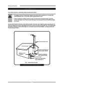
... where it could come in contact with overhead power lines, or any other electric light or power circuits. ▪ When installing an outdoor antenna system, extreme caution should be taken to grounding electrodes, and requirements for the grounding electrode. Direct contact with power lines. Section 810 of National Electrical Code (NEC) provides information with respect to proper grounding...
... where it could come in contact with overhead power lines, or any other electric light or power circuits. ▪ When installing an outdoor antenna system, extreme caution should be taken to grounding electrodes, and requirements for the grounding electrode. Direct contact with power lines. Section 810 of National Electrical Code (NEC) provides information with respect to proper grounding...
User Guide
Page 7
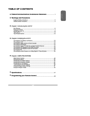
... Your LCD TV...8 Your LCD TV...11 Your Remote Control 13 Chapter 2 Installing the LCD TV Connecting a TV Cable or an Antenna 15 Connecting a VCR ...20 Connecting a Video Camera or Game Console 21 Connecting a DVD Player 22 Connecting a Digital TV Cable Box or Digital Satellite Receiver 24 Connecting an AV Equipment with HDMI Connector 25 Connecting an AV Equipment with DVI Connector 26 Connecting a PC...27 Connecting an Audio Receiver or a Dolby Digital 5.1 Sound System 28 Chapter 3 USING THE FEATURES Wide Screen Viewing...29 Operating the Menu...30 Customizing the VIDEO Settings...32...
... Your LCD TV...8 Your LCD TV...11 Your Remote Control 13 Chapter 2 Installing the LCD TV Connecting a TV Cable or an Antenna 15 Connecting a VCR ...20 Connecting a Video Camera or Game Console 21 Connecting a DVD Player 22 Connecting a Digital TV Cable Box or Digital Satellite Receiver 24 Connecting an AV Equipment with HDMI Connector 25 Connecting an AV Equipment with DVI Connector 26 Connecting a PC...27 Connecting an Audio Receiver or a Dolby Digital 5.1 Sound System 28 Chapter 3 USING THE FEATURES Wide Screen Viewing...29 Operating the Menu...30 Customizing the VIDEO Settings...32...

User Guide
Page 8
... a more natural-looking, clearer image of multiple cables used to connect current A/V systems. HDTV Component Video Inputs ▪ Offers the best video quality for external equipment connection ▪ 2 sets of composite A/V input terminals ▪ 1 set of S-VIDEO terminals ▪ 2 sets of component Video input terminals ▪ 1 VGA/ Audio input terminals ▪ 2 HDMI/Audio input terminals ▪ 1 set of Audio(L/R) output terminals ▪ 2 SPDIF output terminals (Optical x 1 /Coaxial x 1) ▪ 1 Headphone terminal The built-in TV tuner to receive HD ATSC ▪ This function...
... a more natural-looking, clearer image of multiple cables used to connect current A/V systems. HDTV Component Video Inputs ▪ Offers the best video quality for external equipment connection ▪ 2 sets of composite A/V input terminals ▪ 1 set of S-VIDEO terminals ▪ 2 sets of component Video input terminals ▪ 1 VGA/ Audio input terminals ▪ 2 HDMI/Audio input terminals ▪ 1 set of Audio(L/R) output terminals ▪ 2 SPDIF output terminals (Optical x 1 /Coaxial x 1) ▪ 1 Headphone terminal The built-in TV tuner to receive HD ATSC ▪ This function...
User Guide
Page 9
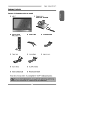
... operate the LCD TV in the package. Make sure all you are missing any items, please contact the Polaroid customer service department. 7 LCD TV Bottom Stand / Screw Driver and Screws ENGLISH Remote Control/ AAA Batteries x 2 SET UP TV CAB/ SAT DVD AUX SLEEP DVD MENU VOL CH PAGE MUTE ASPECT LAST GUIDE LIVE TV PIP MENU OK INFO CC EXIT DVR 1 2 3 ABC DEF 4 5 6 GHI JKL MNO 7 8 9 PQRS TUV WXYZ INPUT . 0 ENTER Power Cord VIDEO Cable Component Cable AUDIO Cable Warranty Card User's Manual Quick Start Guide Stand Assembly Guide Remote control Guide...
... operate the LCD TV in the package. Make sure all you are missing any items, please contact the Polaroid customer service department. 7 LCD TV Bottom Stand / Screw Driver and Screws ENGLISH Remote Control/ AAA Batteries x 2 SET UP TV CAB/ SAT DVD AUX SLEEP DVD MENU VOL CH PAGE MUTE ASPECT LAST GUIDE LIVE TV PIP MENU OK INFO CC EXIT DVR 1 2 3 ABC DEF 4 5 6 GHI JKL MNO 7 8 9 PQRS TUV WXYZ INPUT . 0 ENTER Power Cord VIDEO Cable Component Cable AUDIO Cable Warranty Card User's Manual Quick Start Guide Stand Assembly Guide Remote control Guide...
User Guide
Page 11
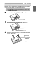
... sure to use the wall mounting kit specified for assistance when installing the wall mounting kit. Contact a qualified technician for your new Polaroid TV on a wall instead of the TV and fasten four screws. 4 screws (supplied with the wall mount kit) Wall mounting hook unit (supplied with the corresponding holes on the wall mounting hook units with the wall mount kit) Soft cloth 9 ENGLISH Chapter 1 Introducing the LCD TV How to remove the TV Stand If...
... sure to use the wall mounting kit specified for assistance when installing the wall mounting kit. Contact a qualified technician for your new Polaroid TV on a wall instead of the TV and fasten four screws. 4 screws (supplied with the wall mount kit) Wall mounting hook unit (supplied with the corresponding holes on the wall mounting hook units with the wall mount kit) Soft cloth 9 ENGLISH Chapter 1 Introducing the LCD TV How to remove the TV Stand If...
User Guide
Page 13
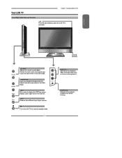
... down through channels. Turns the LCD TV on external video equipment. ENGLISH IR Infrared Receiver VOLUME+Adjusts the volume up and down . VIDEO1 IN Connects to the composite Video and Audio output jacks on and into standby mode. 11 VIDEO L R VIDEO1 IN MENU Press once to display the OSD (on screen display), press again to the external headphone for items when in the OSD mode. INPUT Chooses from different input signal sources. Selects the main-menu item and change values...
... down through channels. Turns the LCD TV on external video equipment. ENGLISH IR Infrared Receiver VOLUME+Adjusts the volume up and down . VIDEO1 IN Connects to the composite Video and Audio output jacks on and into standby mode. 11 VIDEO L R VIDEO1 IN MENU Press once to display the OSD (on screen display), press again to the external headphone for items when in the OSD mode. INPUT Chooses from different input signal sources. Selects the main-menu item and change values...
User Guide
Page 14
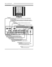
... DVI connection. Chapter 1 Introducing the LCD TV Rear View and Jacks VIDEO2 IN Connects to the composite VIDEO and AUDIO(L/R) output jacks on external video equipment. HDTV/TV Air/CABLE VHF/UHF IN TV CABLE/AIR Connects RF input from VHF/UHF antenna or cable to the AC power cord. 12 HDMI 2 IN HDMI 1 IN AUDIO L R VGA IN AUDIO L R YPbPr1 IN Y Pb Pr AUDIO AUDIO OUT STEREO DIGITAL OPTICAL L R Y Pb Pr L COAXIAL L R VIDEO AUDIO VIDEO2 IN S-VIDEO L AUDIO R S-VIDEO IN L R R YPbPr2 IN AUDIO YPbPr1 IN/YPbPr2 IN Connects to the DVD player, Digital Set-Top-Box...
... DVI connection. Chapter 1 Introducing the LCD TV Rear View and Jacks VIDEO2 IN Connects to the composite VIDEO and AUDIO(L/R) output jacks on external video equipment. HDTV/TV Air/CABLE VHF/UHF IN TV CABLE/AIR Connects RF input from VHF/UHF antenna or cable to the AC power cord. 12 HDMI 2 IN HDMI 1 IN AUDIO L R VGA IN AUDIO L R YPbPr1 IN Y Pb Pr AUDIO AUDIO OUT STEREO DIGITAL OPTICAL L R Y Pb Pr L COAXIAL L R VIDEO AUDIO VIDEO2 IN S-VIDEO L AUDIO R S-VIDEO IN L R R YPbPr2 IN AUDIO YPbPr1 IN/YPbPr2 IN Connects to the DVD player, Digital Set-Top-Box...
User Guide
Page 15
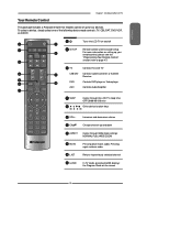
... previously selected channel 11 GUIDE In TV mode, pressing GUIDE displays the Program Guide on and off 2 SET UP Remote control universal code setup. For more information on setting up and down 8 ASPECT Cycles through the LCD TV sleep time: OFF/30/60/90/120 mins Other device function keys 6 VOL+- ENGLISH Your Remote Control Chapter 1 Introducing the LCD TV This package includes a Polaroid remote that enables control of the following device mode controls: TV, CBL/SAT, DVD/VCR, or AUDIO. 2 SET UP 1 3 TV CAB/ SAT DVD AUX SLEEP 4 DVD MENU...
... previously selected channel 11 GUIDE In TV mode, pressing GUIDE displays the Program Guide on and off 2 SET UP Remote control universal code setup. For more information on setting up and down 8 ASPECT Cycles through the LCD TV sleep time: OFF/30/60/90/120 mins Other device function keys 6 VOL+- ENGLISH Your Remote Control Chapter 1 Introducing the LCD TV This package includes a Polaroid remote that enables control of the following device mode controls: TV, CBL/SAT, DVD/VCR, or AUDIO. 2 SET UP 1 3 TV CAB/ SAT DVD AUX SLEEP 4 DVD MENU...
User Guide
Page 16
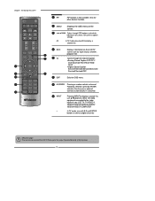
... channel, or channel activates automatically in 3 seconds 19 INPUT Pressing INPUT to display a source list, use ▲▼buttons to select the video equipment connected to the video inputs of your LCD TV: TV/VIDEO1/ VIDEO2/VIDEO3/VIDEO4/VIDEO5/ VIDEO6/VIDEO7/COMPUTER ▪ In TV mode, use with 0-9 and ENTER buttons to select a digital channels Effective range: The remote can control the LCD TV from up to display a channel list 15 INFO Displays information on the screen. 14 OK Cycles through the Closed Caption: Analog Closed Caption...
... channel, or channel activates automatically in 3 seconds 19 INPUT Pressing INPUT to display a source list, use ▲▼buttons to select the video equipment connected to the video inputs of your LCD TV: TV/VIDEO1/ VIDEO2/VIDEO3/VIDEO4/VIDEO5/ VIDEO6/VIDEO7/COMPUTER ▪ In TV mode, use with 0-9 and ENTER buttons to select a digital channels Effective range: The remote can control the LCD TV from up to display a channel list 15 INFO Displays information on the screen. 14 OK Cycles through the Closed Caption: Analog Closed Caption...

User Guide
Page 19
.... RF switch (not included) A OUT IN B 2 set for proper grounding and, in the diagram below. ENGLISH Chapter 2 Installing the LCD TV Cable TV (CATV) Connection This reminder is provided to call the CATV system installer's attention to Article 820-40 of the National Electrical Code (NEC) that the cable ground shall be connected to the grounding system of the building accurately, or as close to the...
.... RF switch (not included) A OUT IN B 2 set for proper grounding and, in the diagram below. ENGLISH Chapter 2 Installing the LCD TV Cable TV (CATV) Connection This reminder is provided to call the CATV system installer's attention to Article 820-40 of the National Electrical Code (NEC) that the cable ground shall be connected to the grounding system of the building accurately, or as close to the...

User Guide
Page 20
... - 5x20mm Time Lag Fuse (Slow Blow) to wall outlet. HDTV/TV Air/CABLE VHF/UHF IN Connect the AC power cord at the back of TV 4A 250V 5x20mm Fuse BE SURE TO UNPLUG AC POWER CORD BEFORE REMOVING THE FUSE. If the fuse is equipped with a safety fuse. The POWER button on the remote to protect your TV. Chapter 2 Installing the LCD TV Use a supplied antenna cable to connect the TV signal to the LCD TV's TV CABLE terminal.
... - 5x20mm Time Lag Fuse (Slow Blow) to wall outlet. HDTV/TV Air/CABLE VHF/UHF IN Connect the AC power cord at the back of TV 4A 250V 5x20mm Fuse BE SURE TO UNPLUG AC POWER CORD BEFORE REMOVING THE FUSE. If the fuse is equipped with a safety fuse. The POWER button on the remote to protect your TV. Chapter 2 Installing the LCD TV Use a supplied antenna cable to connect the TV signal to the LCD TV's TV CABLE terminal.
User Guide
Page 21
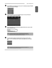
... display the Input List. ENGLISH Chapter 2 Installing the LCD TV Press the button on the remote to turn on the LCD TV. (Scroll down using the UP/DOWN buttons to see Computer-VGA option) Main TV(CABLE/AIR) VIDEO1 (SIDE) VIDEO2 (REAR) VIDEO3 (S-VIDEO) VIDEO4 (YPbPr1) VIDEO5 (YPbPr2) VIDEO6 (HDMI1) VIDEO7 (HDMI2) COMPUTER(VGA) Press the INPUT button on the remote control to display the Main menu, and use the ◄► buttons to select digital channel (for example 9.1) Channel List 5-2 RF5-2 9-1 KQED-HD...
... display the Input List. ENGLISH Chapter 2 Installing the LCD TV Press the button on the remote to turn on the LCD TV. (Scroll down using the UP/DOWN buttons to see Computer-VGA option) Main TV(CABLE/AIR) VIDEO1 (SIDE) VIDEO2 (REAR) VIDEO3 (S-VIDEO) VIDEO4 (YPbPr1) VIDEO5 (YPbPr2) VIDEO6 (HDMI1) VIDEO7 (HDMI2) COMPUTER(VGA) Press the INPUT button on the remote control to display the Main menu, and use the ◄► buttons to select digital channel (for example 9.1) Channel List 5-2 RF5-2 9-1 KQED-HD...

User Guide
Page 23
...jack to the LCD TV's audio inputs. Not all AC power sources, before turning on the power switch of TV HDMI 2 IN HDMI 1 IN AUDIO L R VGA IN AUDIO L R VIDEO L R AUDIO VIDEO2 IN S-VIDEO L AUDIO R S-VIDEO IN YPbPr1 IN Y Pb Pr AUDIO AUDIO OUT STEREO DIGITAL OPTICAL L R Y Pb Pr L COAXIAL L R R YPbPr2 IN AUDIO HDTV/TV Air/CABLE VHF/UHF IN AUDIO Cable or S-VIDEO Cable GAME CONSOLE B AV Cable NOTE: The connections shown for compatibility. 21 ENGLISH Connecting a Video Camera or Game console Chapter 2 Installing the LCD TV Right Side VIDEO L R VIDEO1 IN Rear...
...jack to the LCD TV's audio inputs. Not all AC power sources, before turning on the power switch of TV HDMI 2 IN HDMI 1 IN AUDIO L R VGA IN AUDIO L R VIDEO L R AUDIO VIDEO2 IN S-VIDEO L AUDIO R S-VIDEO IN YPbPr1 IN Y Pb Pr AUDIO AUDIO OUT STEREO DIGITAL OPTICAL L R Y Pb Pr L COAXIAL L R R YPbPr2 IN AUDIO HDTV/TV Air/CABLE VHF/UHF IN AUDIO Cable or S-VIDEO Cable GAME CONSOLE B AV Cable NOTE: The connections shown for compatibility. 21 ENGLISH Connecting a Video Camera or Game console Chapter 2 Installing the LCD TV Right Side VIDEO L R VIDEO1 IN Rear...
User Guide
Page 26
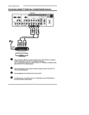
... Receiver Rear of the LCD TV or other connected equipment. Press the button on the remote to the LCD TV's component input jacks. Connect all AC power sources, before turning on the remote to the LCD TV's audio input jacks. To watch programs via satellite receiver or TV Cable Box, press the INPUT button on the power switch of TV HDMI 2 IN HDMI 1 IN AUDIO L R VGA IN AUDIO L R L R VIDEO AUDIO VIDEO2 IN S-VIDEO L AUDIO R S-VIDEO IN YPbPr1 IN Y Pb Pr AUDIO AUDIO OUT STEREO DIGITAL OPTICAL L R Y Pb Pr L COAXIAL L R R YPbPr2 IN AUDIO HDTV/TV Air/CABLE VHF...
... Receiver Rear of the LCD TV or other connected equipment. Press the button on the remote to the LCD TV's component input jacks. Connect all AC power sources, before turning on the remote to the LCD TV's audio input jacks. To watch programs via satellite receiver or TV Cable Box, press the INPUT button on the power switch of TV HDMI 2 IN HDMI 1 IN AUDIO L R VGA IN AUDIO L R L R VIDEO AUDIO VIDEO2 IN S-VIDEO L AUDIO R S-VIDEO IN YPbPr1 IN Y Pb Pr AUDIO AUDIO OUT STEREO DIGITAL OPTICAL L R Y Pb Pr L COAXIAL L R R YPbPr2 IN AUDIO HDTV/TV Air/CABLE VHF...

User Guide
Page 33
..., Closed Caption,Factory Reset, Parental Control, and Sleep Timer. ▪ If the signal source is TV/VIDEO/S-VIDEO/YPbPr, the SETUP MENU appears as: ▪ If the signal source is HDMI/VGA, the SETUP MENU appears as: OSD Language Time Setup Closed Caption Parental Gamma Reset Default English Middle OSD Language Time Setup Parental Gamma Reset Default English Middle Use the ▲▼ buttons to change the value of the sub-menu, and press the OK button. Channel Scan Tuner Mode Channel Skip Time Zone Cable Eastern Time Chapter 3 Using the LCD TV TV Select Exit SETUP MENU...
..., Closed Caption,Factory Reset, Parental Control, and Sleep Timer. ▪ If the signal source is TV/VIDEO/S-VIDEO/YPbPr, the SETUP MENU appears as: ▪ If the signal source is HDMI/VGA, the SETUP MENU appears as: OSD Language Time Setup Closed Caption Parental Gamma Reset Default English Middle OSD Language Time Setup Parental Gamma Reset Default English Middle Use the ▲▼ buttons to change the value of the sub-menu, and press the OK button. Channel Scan Tuner Mode Channel Skip Time Zone Cable Eastern Time Chapter 3 Using the LCD TV TV Select Exit SETUP MENU...
User Guide
Page 39
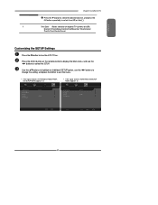
... individual SETUP option, use the ◄► buttons to turn the LCD TV on the remote control to display the Main menu, and use the ◄► buttons to change the setting, and press the MENU to exit the menu. ▪ If the signal source is TV/VIDOE/S-VIDEO/YPbPr, the SETUP MENU appears as: ▪ If the signal source is HDMI/VGA, the SETUP MENU appears as: OSD Language Time Setup Closed Caption Parental Gamma Reset Default English Middle OSD Language Time Setup Parental Gamma Reset Default English Middle Setup Select...
... individual SETUP option, use the ◄► buttons to turn the LCD TV on the remote control to display the Main menu, and use the ◄► buttons to change the setting, and press the MENU to exit the menu. ▪ If the signal source is TV/VIDOE/S-VIDEO/YPbPr, the SETUP MENU appears as: ▪ If the signal source is HDMI/VGA, the SETUP MENU appears as: OSD Language Time Setup Closed Caption Parental Gamma Reset Default English Middle OSD Language Time Setup Parental Gamma Reset Default English Middle Setup Select...
User Guide
Page 42
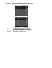
...LCD TV Gamma Reset Default Channel Block Allows to block digital channels. 2 ABC 3 DISC 4 5 6 7 8 9 10 Analog Analog Analog Analog Analog Analog Analog Analog Analog Channel Block Input Block Set OK Select Exit Selects to block a Input source signal 1 TV(CABLE/AIR) 2 VIDEO1 (Side) 3 VIDEO2 (S-VIDEO) 4 VIDEO3 (REAR) 5 VIDEO4 (YPbPr1) 6 VIDEO5 (YPbPr2) 7 VIDEO6 (HDMI1) 8 VIDEO7 (HDMI2) 9 COMPUTER(VGA) Channel Block Set OK Select Exit Change Password Selects to restore factory settings 40 Press the OK button to change your password Allows adjustment of the display...
...LCD TV Gamma Reset Default Channel Block Allows to block digital channels. 2 ABC 3 DISC 4 5 6 7 8 9 10 Analog Analog Analog Analog Analog Analog Analog Analog Analog Channel Block Input Block Set OK Select Exit Selects to block a Input source signal 1 TV(CABLE/AIR) 2 VIDEO1 (Side) 3 VIDEO2 (S-VIDEO) 4 VIDEO3 (REAR) 5 VIDEO4 (YPbPr1) 6 VIDEO5 (YPbPr2) 7 VIDEO6 (HDMI1) 8 VIDEO7 (HDMI2) 9 COMPUTER(VGA) Channel Block Set OK Select Exit Change Password Selects to restore factory settings 40 Press the OK button to change your password Allows adjustment of the display...


