User Manual
Page 1
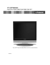
15" LCD Television FLM-1514, FLM-1514B, FLM-153B, FLM-1517 Your LCD TV may look slightly different from the one pictured above. 20061004
15" LCD Television FLM-1514, FLM-1514B, FLM-153B, FLM-1517 Your LCD TV may look slightly different from the one pictured above. 20061004
User Manual
Page 2
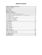
Table Of Contents Important Safety Instructions 1 Product Features 3 Front Panel 4 Rear Panel 5 Remote Control 6 System Connections 8 Connecting to External AV Signal Source 8 Connecting to External AV Signal Source (Component 10 Connecting to PC 11 Connecting to Power Cable 12 Connecting to TV Signal 13 Connecting to Headphones 15 TV Functions 14 Preparations 14 Image Setting 14 Audio Setting 15 Sleep Setting 16 Parental Setting 17 Setup Setting 20 Other Functions 23 External AV Input Function 23 Computer Screen Function 23 Troubleshooting 24 Specifications 25 1
Table Of Contents Important Safety Instructions 1 Product Features 3 Front Panel 4 Rear Panel 5 Remote Control 6 System Connections 8 Connecting to External AV Signal Source 8 Connecting to External AV Signal Source (Component 10 Connecting to PC 11 Connecting to Power Cable 12 Connecting to TV Signal 13 Connecting to Headphones 15 TV Functions 14 Preparations 14 Image Setting 14 Audio Setting 15 Sleep Setting 16 Parental Setting 17 Setup Setting 20 Other Functions 23 External AV Input Function 23 Computer Screen Function 23 Troubleshooting 24 Specifications 25 1
User Manual
Page 3
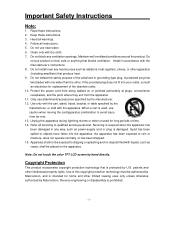
... do so. Don't perform any servicing other than that all the connections have difficulty inserting the plug, turn it over and reinsert it. If you are for use by qualified service personnel only. If the unit will not the used for servicing instructions. - 2 - POWER SUPPLY: Plug the two-prong end of the power cord to service manual for a long time, disconnect the plug from the outlet. Refer to...
... do so. Don't perform any servicing other than that all the connections have difficulty inserting the plug, turn it over and reinsert it. If you are for use by qualified service personnel only. If the unit will not the used for servicing instructions. - 2 - POWER SUPPLY: Plug the two-prong end of the power cord to service manual for a long time, disconnect the plug from the outlet. Refer to...
User Manual
Page 4
... not block any heat sources such as power-supply cord or plug is used, use caution when moving the cart/apparatus combination to rain or moisture, does not operate normally, or has been dropped. 15. Install in any way, such as radiators, heat registers, stoves, or other . Read these instructions. 3. patents and other limited viewing uses only unless otherwise authorized by Macrovision...
... not block any heat sources such as power-supply cord or plug is used, use caution when moving the cart/apparatus combination to rain or moisture, does not operate normally, or has been dropped. 15. Install in any way, such as radiators, heat registers, stoves, or other . Read these instructions. 3. patents and other limited viewing uses only unless otherwise authorized by Macrovision...

User Manual
Page 5
... crystal display clearly shows the data. AV and VGA Input Can be connected to experience some light or dark spots appearing on the LCD screen. Auto TV Searching Function Can be connected external audio and video signal source and PC. - 4 - Stereo amplifier Built-in one system. Product Features This product incorporates LCD display and TV receiver in 2x3w stereo speakers provide high quality sound. Multiple Mode Component mode VGA mode TV mode Composite mode S-VIDEO mode Special Function Support sleep time setting function...
... crystal display clearly shows the data. AV and VGA Input Can be connected to experience some light or dark spots appearing on the LCD screen. Auto TV Searching Function Can be connected external audio and video signal source and PC. - 4 - Stereo amplifier Built-in one system. Product Features This product incorporates LCD display and TV receiver in 2x3w stereo speakers provide high quality sound. Multiple Mode Component mode VGA mode TV mode Composite mode S-VIDEO mode Special Function Support sleep time setting function...
User Manual
Page 6
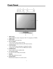
In setup menu, the same function as ◄/►direction buttons. 5. Speaker Output high quality stereo sound. 8. INPUT button Press to select channels. CH ▲/▼ button In the TV mode, press to select the modes: Component, VGA, TV, Composite or S-VIDEO. 2. In setup menu, the same function as ▲/▼ direction buttons. 4. Front Panel 1. Remote Sensor Remote sensor window for the remote control. - 5 - POWER button Press to enter or exit setup menu. 3. MENU button Press to enter or exit the standby mode. 6. 15" color TFT screen 15" color TFT screen ...
In setup menu, the same function as ◄/►direction buttons. 5. Speaker Output high quality stereo sound. 8. INPUT button Press to select channels. CH ▲/▼ button In the TV mode, press to select the modes: Component, VGA, TV, Composite or S-VIDEO. 2. In setup menu, the same function as ▲/▼ direction buttons. 4. Front Panel 1. Remote Sensor Remote sensor window for the remote control. - 5 - POWER button Press to enter or exit setup menu. 3. MENU button Press to enter or exit the standby mode. 6. 15" color TFT screen 15" color TFT screen ...
User Manual
Page 7
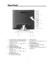
.../ L/R Audio Input Jack Connected to the Component (YPbPr) input in Composite mode. DC 9.5V/12V In Jack Connected to the VGA output jack on a personal computer. 6. TV Signal Input Jack Connected for the external NTSC TV signal input. - 6 - VGA Input Jack Connected to power adapter. 5. S-VIDEO Input Jacks 3. VIDEO/L/R Audio Input Jack Connected to the L/R audio input in Composite mode. 4. Connected to the VIDEO input in Component mode. PC AUDIO Input Jack Connected to the L/R audio input in Component mode. 2. Connected to the PC audio output jack. 7. Rear Panel 1.
.../ L/R Audio Input Jack Connected to the Component (YPbPr) input in Composite mode. DC 9.5V/12V In Jack Connected to the VGA output jack on a personal computer. 6. TV Signal Input Jack Connected for the external NTSC TV signal input. - 6 - VGA Input Jack Connected to power adapter. 5. S-VIDEO Input Jacks 3. VIDEO/L/R Audio Input Jack Connected to the L/R audio input in Composite mode. 4. Connected to the VIDEO input in Component mode. PC AUDIO Input Jack Connected to the L/R audio input in Component mode. 2. Connected to the PC audio output jack. 7. Rear Panel 1.

User Manual
Page 8
... the LCD setup menu. 15. MENU button Press to display the closed captions or cancel display. 11. CH +/- button In TV mode, press to the channel last viewed. 4. LAST button In the TV mode, press to return to select channel. - 7 - MTS button Press to adjust or set. 6. Direction buttons In the setup menu, press the ▲▼button to select the desired item and press the ◄► button to activate MTS function in TV mode. 12. button Press to exit the setup menu. 16. Remote Control Remote Control...
... the LCD setup menu. 15. MENU button Press to display the closed captions or cancel display. 11. CH +/- button In TV mode, press to the channel last viewed. 4. LAST button In the TV mode, press to return to select channel. - 7 - MTS button Press to adjust or set. 6. Direction buttons In the setup menu, press the ▲▼button to select the desired item and press the ◄► button to activate MTS function in TV mode. 12. button Press to exit the setup menu. 16. Remote Control Remote Control...
User Manual
Page 10
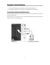
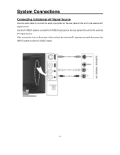
After connection, turn on the rear panel of the unit and the external AV signal source and then press the INPUT button to shift to the external AV signal source. Connecting to External AV Signal Source Use the audio and video cable to connect the AV input jacks on the power of the unit to Composite mode. - 9 - System Connections • Do not connect the power cord until all other connections have been made. • Ensure that you observe the color cord when connecting audio and video cables.
After connection, turn on the rear panel of the unit and the external AV signal source and then press the INPUT button to shift to the external AV signal source. Connecting to External AV Signal Source Use the audio and video cable to connect the AV input jacks on the power of the unit to Composite mode. - 9 - System Connections • Do not connect the power cord until all other connections have been made. • Ensure that you observe the color cord when connecting audio and video cables.
User Manual
Page 11
After connection, turn on the power of the unit and the external AV signal source and then press the INPUT button to shift to the external AV signal source. System Connections Connecting to External AV Signal Source Use the audio cable to connect the audio input jacks on the rear panel of the unit to S-VIDEO mode. - 10 - Use the S-VIDEO cable to connect the S-VIDEO input jack on the rear panel of the unit to the external AV signal source.
After connection, turn on the power of the unit and the external AV signal source and then press the INPUT button to shift to the external AV signal source. System Connections Connecting to External AV Signal Source Use the audio cable to connect the audio input jacks on the rear panel of the unit to S-VIDEO mode. - 10 - Use the S-VIDEO cable to connect the S-VIDEO input jack on the rear panel of the unit to the external AV signal source.
User Manual
Page 12
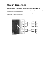
System Connections Connecting to External AV Signal Source (COMPONENT) Use the audio and video cables to connect the COMPONENT (Y/Pb/Pr) input Jacks on the power of the unit to Component mode. - 11 - After connection, turn on the rear panel of the unit and external AV signal source and then press the INPUT button to shift to the external AV signal source.
System Connections Connecting to External AV Signal Source (COMPONENT) Use the audio and video cables to connect the COMPONENT (Y/Pb/Pr) input Jacks on the power of the unit to Component mode. - 11 - After connection, turn on the rear panel of the unit and external AV signal source and then press the INPUT button to shift to the external AV signal source.
User Manual
Page 13
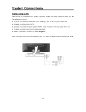
... the VGA cable to the VGA input jack on the rear panel of the unit. 2. Connect the other end to the PC audio output jack. 5. Follow the steps and the figure below to PC (person computer) via the VGA cable. Connect the other end to the PC. 3. Please set the PC's resolution at 1024x768@60Hz After connection, turn on the unit and the PC and then press the INPUT button...
... the VGA cable to the VGA input jack on the rear panel of the unit. 2. Connect the other end to the PC audio output jack. 5. Follow the steps and the figure below to PC (person computer) via the VGA cable. Connect the other end to the PC. 3. Please set the PC's resolution at 1024x768@60Hz After connection, turn on the unit and the PC and then press the INPUT button...
User Manual
Page 15
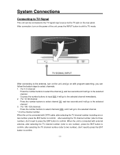
... is connected with external antenna, after selecting the TV channel number (refer to one or two number, press the ENT button to confirm, after selecting the TV channel number (refer to two number), don't need to press the ENT button to the TV signal input source via the TV jack on the rear panel. System Connections Connecting to TV Signal This unit can follow the below steps to the selected channel. * X is connected with CATV cable, after selecting the TV channel number including one number), press...
... is connected with external antenna, after selecting the TV channel number (refer to one or two number, press the ENT button to confirm, after selecting the TV channel number (refer to two number), don't need to press the ENT button to the TV signal input source via the TV jack on the rear panel. System Connections Connecting to TV Signal This unit can follow the below steps to the selected channel. * X is connected with CATV cable, after selecting the TV channel number including one number), press...
User Manual
Page 16
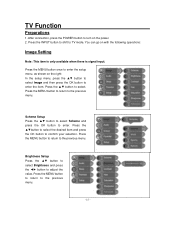
... enter. Scheme Setup Press the ▲▼ button to select Scheme and press the OK button to confirm your selection. Press the MENU button to return to TV mode. TV Function Preparations 1. Press the INPUT button to shift to the previous menu. After connection, press the POWER button to enter the setup menu, as shown on with the following operations: Image Setting Note: This item is only available when there is signal input.
... enter. Scheme Setup Press the ▲▼ button to select Scheme and press the OK button to confirm your selection. Press the MENU button to return to TV mode. TV Function Preparations 1. Press the INPUT button to shift to the previous menu. After connection, press the POWER button to enter the setup menu, as shown on with the following operations: Image Setting Note: This item is only available when there is signal input.
User Manual
Page 17
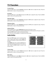
... menu. Audio Setting Press the MENU button once to adjust the level. Bass Setup Press the ▲▼button to select Bass and press the ◄► button to enter the setup menu. Press the MENU button to return to enter. In the Audio setup menu, press the ▲▼ button to select the desired item and press the OK button to the previous menu. - 16 - Volume Setup Press the ▲▼ button to select Volume...
... menu. Audio Setting Press the MENU button once to adjust the level. Bass Setup Press the ▲▼button to select Bass and press the ◄► button to enter the setup menu. Press the MENU button to return to enter. In the Audio setup menu, press the ▲▼ button to select the desired item and press the OK button to the previous menu. - 16 - Volume Setup Press the ▲▼ button to select Volume...
User Manual
Page 19
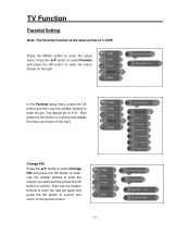
... the previous menu. - 18 - The default pin is the same as shown on the right. Then use the number buttons to enter. Press the ▲▼ button to select Parental and press the OK button to continue and display the menu as that of V-CHIP. Then press the OK button to enter the menu shown on the right. TV Function Parental Setting Note: The Parental Function is...
... the previous menu. - 18 - The default pin is the same as shown on the right. Then use the number buttons to enter. Press the ▲▼ button to select Parental and press the OK button to continue and display the menu as that of V-CHIP. Then press the OK button to enter the menu shown on the right. TV Function Parental Setting Note: The Parental Function is...
User Manual
Page 22
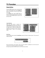
... OK button to enter the setup menu. The screen will exit and memorize the programs by sequence automatically. TV Function Setup Setting Press the MENU button once to enter. Tuner/Channel Press the ▲▼ button to select the Tuner/Channel and press the OK button to exit the auto scan mode. - 21 - During tuning, press the MENU button to enter the menu as below: Auto scan will take a few minutes, when the tuning operation completes...
... OK button to enter the setup menu. The screen will exit and memorize the programs by sequence automatically. TV Function Setup Setting Press the MENU button once to enter. Tuner/Channel Press the ▲▼ button to select the Tuner/Channel and press the OK button to exit the auto scan mode. - 21 - During tuning, press the MENU button to enter the menu as below: Auto scan will take a few minutes, when the tuning operation completes...
User Manual
Page 25
... the external AV signal source such as the computer screen. Then turn on to the PC and then you can be used as recorder, vidicon, satellite receiver or game player etc. Note: Some of connecting the unit to set the PC's resolution at: 1024 x 768@60Hz. Press the INPUT button to shift to the introduction in these menus in S-VIDEO, Composite, Component and VGA modes are...
... the external AV signal source such as the computer screen. Then turn on to the PC and then you can be used as recorder, vidicon, satellite receiver or game player etc. Note: Some of connecting the unit to set the PC's resolution at: 1024 x 768@60Hz. Press the INPUT button to shift to the introduction in these menus in S-VIDEO, Composite, Component and VGA modes are...
User Manual
Page 26
... power-supply cord from the outlet and plug it in correct video type. Make sure system connection is correctly connected. LCD does not display a picture. Check if the connections with the external AV signal source are inserted and the polarity is no sound. There is correct. Make sure the remote control is turned on and the connections are not weak. Note about External Interference: Static or other external interfere may need to reset...
... power-supply cord from the outlet and plug it in correct video type. Make sure system connection is correctly connected. LCD does not display a picture. Check if the connections with the external AV signal source are inserted and the polarity is no sound. There is correct. Make sure the remote control is turned on and the connections are not weak. Note about External Interference: Static or other external interfere may need to reset...
User Manual
Page 27
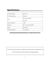
Specifications TFT-LCD Resolution TFT-LCD Screen Size Power Power Consumption Dimension Weight Ambient Temperature 1024 x 768 15 inches AC100~240V 50/60Hz DC 12V 4A < 48W 345 × 84 × 390mm (LXWXD) About 5.8Kg 10~45 degrees DESIGN AND SPECIFICATIONS ARE SUBJECT TO CHANGE WITHOUT NOTICE "Polaroid" and "Polaroid and Pixel" are trademarks of Polaroid Corporation, Waltham, MA, USA. For service, support and warranty information, visit www.polaroid.com. - 26 -
Specifications TFT-LCD Resolution TFT-LCD Screen Size Power Power Consumption Dimension Weight Ambient Temperature 1024 x 768 15 inches AC100~240V 50/60Hz DC 12V 4A < 48W 345 × 84 × 390mm (LXWXD) About 5.8Kg 10~45 degrees DESIGN AND SPECIFICATIONS ARE SUBJECT TO CHANGE WITHOUT NOTICE "Polaroid" and "Polaroid and Pixel" are trademarks of Polaroid Corporation, Waltham, MA, USA. For service, support and warranty information, visit www.polaroid.com. - 26 -


